Transcription
Catalyst 2960 Switch Getting StartedGuideCorporate HeadquartersCisco Systems, Inc.170 West Tasman DriveSan Jose, CA 95134-1706USAhttp://www.cisco.comTel: 408 526-4000800 553-NETS (6387)Fax: 408 526-4100Text Part Number: OL-9368-01
THE SPECIFICATIONS AND INFORMATION REGARDING THE PRODUCTS IN THIS MANUAL ARE SUBJECT TO CHANGE WITHOUTNOTICE. ALL STATEMENTS, INFORMATION, AND RECOMMENDATIONS IN THIS MANUAL ARE BELIEVED TO BE ACCURATE BUTARE PRESENTED WITHOUT WARRANTY OF ANY KIND, EXPRESS OR IMPLIED. USERS MUST TAKE FULL RESPONSIBILITY FORTHEIR APPLICATION OF ANY PRODUCTS.THE SOFTWARE LICENSE AND LIMITED WARRANTY FOR THE ACCOMPANYING PRODUCT ARE SET FORTH IN THE INFORMATIONPACKET THAT SHIPPED WITH THE PRODUCT AND ARE INCORPORATED HEREIN BY THIS REFERENCE. IF YOU ARE UNABLE TOLOCATE THE SOFTWARE LICENSE OR LIMITED WARRANTY, CONTACT YOUR CISCO REPRESENTATIVE FOR A COPY.The following information is for FCC compliance of Class A devices: This equipment has been tested and found to comply with the limits for a ClassA digital device, pursuant to part 15 of the FCC rules. These limits are designed to provide reasonable protection against harmful interference whenthe equipment is operated in a commercial environment. This equipment generates, uses, and can radiate radio-frequency energy and, if not installedand used in accordance with the instruction manual, may cause harmful interference to radio communications. Operation of this equipment in aresidential area is likely to cause harmful interference, in which case users will be required to correct the interference at their own expense.The following information is for FCC compliance of Class B devices: The equipment described in this manual generates and may radiateradio-frequency energy. If it is not installed in accordance with Cisco’s installation instructions, it may cause interference with radio and televisionreception. This equipment has been tested and found to comply with the limits for a Class B digital device in accordance with the specifications inpart 15 of the FCC rules. These specifications are designed to provide reasonable protection against such interference in a residential installation.However, there is no guarantee that interference will not occur in a particular installation.Modifying the equipment without Cisco’s written authorization may result in the equipment no longer complying with FCC requirements for ClassA or Class B digital devices. In that event, your right to use the equipment may be limited by FCC regulations, and you may be required to correctany interference to radio or television communications at your own expense.You can determine whether your equipment is causing interference by turning it off. If the interference stops, it was probably caused by the Ciscoequipment or one of its peripheral devices. If the equipment causes interference to radio or television reception, try to correct the interference byusing one or more of the following measures: Turn the television or radio antenna until the interference stops. Move the equipment to one side or the other of the television or radio. Move the equipment farther away from the television or radio. Plug the equipment into an outlet that is on a different circuit from the television or radio. (That is, make certain the equipment and the televisionor radio are on circuits controlled by different circuit breakers or fuses.)Modifications to this product not authorized by Cisco Systems, Inc. could void the FCC approval and negate your authority to operate the product.The Cisco implementation of TCP header compression is an adaptation of a program developed by the University of California, Berkeley (UCB) aspart of UCB’s public domain version of the UNIX operating system. All rights reserved. Copyright 1981, Regents of the University of California.NOTWITHSTANDING ANY OTHER WARRANTY HEREIN, ALL DOCUMENT FILES AND SOFTWARE OF THESE SUPPLIERS AREPROVIDED “AS IS” WITH ALL FAULTS. CISCO AND THE ABOVE-NAMED SUPPLIERS DISCLAIM ALL WARRANTIES, EXPRESSEDOR IMPLIED, INCLUDING, WITHOUT LIMITATION, THOSE OF MERCHANTABILITY, FITNESS FOR A PARTICULAR PURPOSE ANDNONINFRINGEMENT OR ARISING FROM A COURSE OF DEALING, USAGE, OR TRADE PRACTICE.IN NO EVENT SHALL CISCO OR ITS SUPPLIERS BE LIABLE FOR ANY INDIRECT, SPECIAL, CONSEQUENTIAL, OR INCIDENTALDAMAGES, INCLUDING, WITHOUT LIMITATION, LOST PROFITS OR LOSS OR DAMAGE TO DATA ARISING OUT OF THE USE ORINABILITY TO USE THIS MANUAL, EVEN IF CISCO OR ITS SUPPLIERS HAVE BEEN ADVISED OF THE POSSIBILITY OF SUCHDAMAGES.
CCSP, CCVP, the Cisco Square Bridge logo, Follow Me Browsing, and StackWise are trademarks of Cisco Systems, Inc.; Changing the Way WeWork, Live, Play, and Learn, and iQuick Study are service marks of Cisco Systems, Inc.; and Access Registrar, Aironet, BPX, Catalyst, CCDA,CCDP, CCIE, CCIP, CCNA, CCNP, Cisco, the Cisco Certified Internetwork Expert logo, Cisco IOS, Cisco Press, Cisco Systems, Cisco SystemsCapital, the Cisco Systems logo, Cisco Unity, Enterprise/Solver, EtherChannel, EtherFast, EtherSwitch, Fast Step, FormShare, GigaDrive,GigaStack, HomeLink, Internet Quotient, IOS, IP/TV, iQ Expertise, the iQ logo, iQ Net Readiness Scorecard, LightStream, Linksys, MeetingPlace,MGX, the Networkers logo, Networking Academy, Network Registrar, Packet, PIX, Post-Routing, Pre-Routing, ProConnect, RateMUX,ScriptShare, SlideCast, SMARTnet, The Fastest Way to Increase Your Internet Quotient, and TransPath are registered trademarks of Cisco Systems,Inc. and/or its affiliates in the United States and certain other countries.All other trademarks mentioned in this document or Website are the property of their respective owners. The use of the word partner does not implya partnership relationship between Cisco and any other company. (0601R)Catalyst 2960 Switch Getting Started Guide 2006 Cisco Systems, Inc. All rights reserved.
C H A P T E R1Getting Started GuideAbout This GuideThis guide provides instructions on how to use Express Setup to initiallyconfigure your Catalyst switch. Also covered are switch management options,basic rack-mounting procedures, port and module connections, power connectionprocedures, and troubleshooting help.For additional installation and configuration information for Catalyst 2960switches, see the Catalyst 2960 documentation on Cisco.com. For systemrequirements, important notes, limitations, open and resolved bugs, andlast-minute documentation updates, see the release notes, also on Cisco.com.When using the online publications, refer to the documents that match the CiscoIOS software version running on the switch. The software version is on the CiscoIOS label on the switch rear panel.For translations of the warnings that appear in this publication, see the RegulatoryCompliance and Safety Information for the Catalyst 2960 Switch thataccompanies this guide.Catalyst 2960 Switch Getting Started GuideOL-9368-011-1
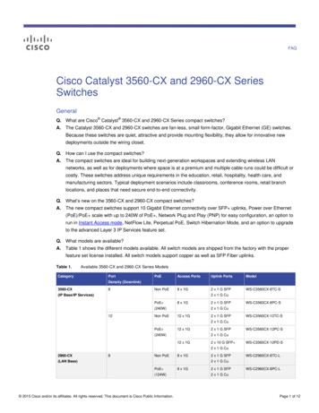
Chapter 1Getting Started GuideTaking Out What You NeedTaking Out What You NeedFollow these steps:1.Unpack and remove the switch and the accessory kit from the shipping box.2.Return the packing material to the shipping container, and save it for futureuse.3.Verify that you have received the items shown in the “Shipping BoxContents” section. If any item is missing or damaged, contact your Ciscorepresentative or reseller for instructions. Some switch models might includeadditional items that are not shown.Equipment That You Supply to Run Express SetupYou need to supply this equipment to run Express Setup: PC Ethernet (Category 5) straight-through cable (as shown)Catalyst 2960 Switch Getting Started Guide1-2OL-9368-01
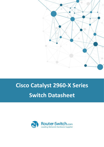
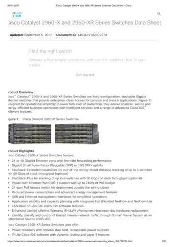
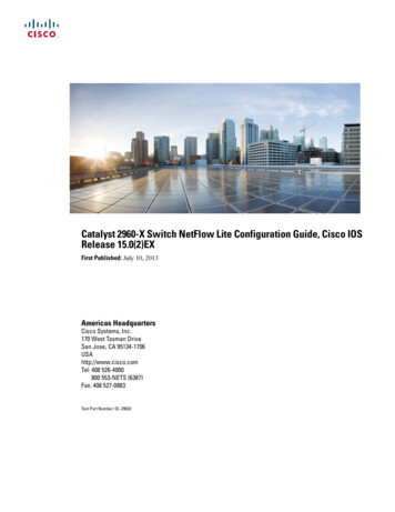
Chapter 1Getting Started GuideTaking Out What You NeedShipping Box 5X14X24X36X38X37X39XCatalyst 2960 SERIE26X47XS1248XCatalyst 2960 switchTwo 19-inchmounting bracketsFour number-12 Phillips machine screwsFour number-8 Phillips truss-head screwsConsole cableSix number-8 Phillips flat-head screwsConnector cover for redundantpower system (RPS)AC power cordTwo number-4 pan-head screwsFour rubber mounting feetoctncnetiowOtraOne black Phillips machine screwphirsardencia onpl tiaom rmhC oitcy Infwor y e Sat et th 0ul af for 96eg St2R ndysaalatCscugishitcw deS ui0 G96 edt 2 artys tal Sat ngC ttieGCidroPReCable guide154190DocumentationCatalyst 2960 Switch Getting Started GuideOL-9368-011-3
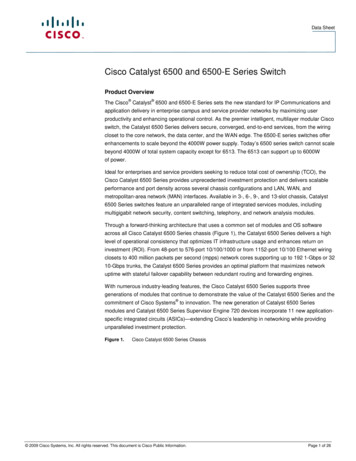
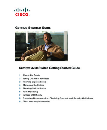
Chapter 1Getting Started GuideRunning Express SetupRunning Express SetupWhen you first set up the switch, you should use Express Setup to enter the initialIP information. This enables the switch to connect to local routers and theInternet. You can then access the switch through the IP address for furtherconfiguration.To run Express Setup:Step 1 Verify that no devices are connected to the switch, because during Express Setup, the switchacts as a DHCP server. If your PC has a static IP address, before you begin, you should changeyour PC settings to temporarily use DHCP.Step 2 Connect the AC power cord to the switch and to a grounded AC outlet. The power-on self-test(POST) begins. During POST, the LEDs blink while a series of tests verify that the switchfunctions properly. LED behavior during POST is unpredictable and might vary.Step 3 Wait for the switch to complete POST. It might take several minutes for the switch to completePOST.Step 4 Verify that POST has completed by confirming that the SYST LED rapidly blinks green. If theswitch fails POST, the SYST LED turns amber.POST errors are usually fatal. Call Cisco Systems immediately if your switch fails POST.Step 5 Press and hold the Mode button for 3seconds. When all of the LEDs abovethe Mode button turn green, releasethe Mode button.1XSYSTRPSSTATDUPLXSPEED11X2XMODE12XMode button135015If the LEDs above the Mode buttonbegin to blink after you press thebutton, release it. Blinking LEDsmean that the switch has already beenconfigured and cannot go intoExpress Setup mode. For moreinformation, see the “Resetting theSwitch” section on page 1-18.Step 6 Verify that the switch is in Express Setup mode by confirming that all LEDs above the Modebutton are green. (The RPS LED remains off on some switch models.)Catalyst 2960 Switch Getting Started Guide1-4OL-9368-01
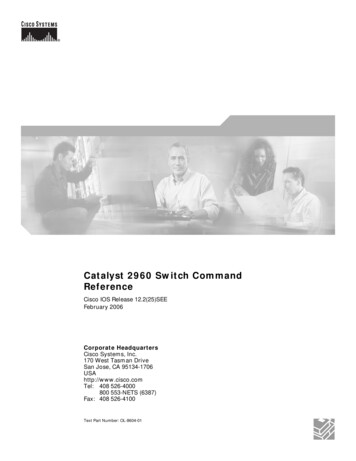
Chapter 1Getting Started GuideRunning Express SetupStep 7 Connect a 7X141682Category 5 Ethernet cable (notprovided) to any 10/100 or10/100/1000 Ethernet port on theswitch front panel and to the Ethernetport on the PC.1248XDHCP-enabled PCStep 8 Verify that the LEDs on both Ethernet ports are green.Step 9 Wait 30 seconds.Step 10 Launch a web browser on your PC.Enter the IP address 10.0.0.1 in theweb browser, and press Enter.Step 11 The Express Setup page appears. If it does not appear, see the “In Case of Difficulty” sectionon page 1-17 for help. Note: all entries must be in English letters and numbers.Catalyst 2960 Switch Getting Started GuideOL-9368-011-5
Chapter 1Getting Started GuideRunning Express SetupStep 12 Enter this information in the Network Settings fields: In the Management Interface (VLAN ID) field, the default is 1. Enter a new VLAN IDonly if you want to change the management interface through which you manage the switchand to which you assign IP information. The VLAN ID range is 1 to 1001. In the IP Address field, enter the IP address of the switch. In the IP Subnet Mask field,click the drop-down arrow, and select an IP Subnet Mask. In the Default Gateway field, enter the IP address for the default gateway (router). Enter your password in the Switch Password field. The password can be from 1 to 25alphanumeric characters, can start with a number, is case sensitive, allows embeddedspaces, but does not allow spaces at the beginning or end. In the Confirm SwitchPassword field, enter your password again.Step 13 (Optional) You can enter the Optional Settings information now or enter it later by using thedevice manager interface: In the Host Name field, enter a name for the switch. The host name is limited to 31characters; embedded spaces are not allowed. In the System Contact field, enter the name of the person responsible for the switch. In theSystem Location field, enter the wiring closet, floor, or building where the switch islocated. In the Telnet Access field, click Enable if you are going to use Telnet to manage the switchby using the command-line interface (CLI). If you enable Telnet access, you must enter aTelnet password. In the Telnet Password field, enter a password. The Telnet password can be from 1 to 25alphanumeric characters, is case sensitive, allows embedded spaces, but does not allowspaces at the beginning or end. In the Confirm Telnet Password field, enter the Telnetpassword again. In the SNMP field, click Enable to enable Simple Network Management Protocol(SNMP). Enable SNMP only if you plan to manage switches by using CiscoWorks2000 oranother SNMP-based network-management system.If you enable SNMP, you must enter a community string in the SNMP Read Communityfield, the SNMP Write Community field, or both. SNMP community strings authenticateaccess to MIB objects. Embedded spaces are not allowed in SNMP community strings.When you set the SNMP read community, you can access SNMP information, but cannotmodify it. When you set the SNMP write community, you can access and modify SNMPinformation.Catalyst 2960 Switch Getting Started Guide1-6OL-9368-01
Chapter 1Getting Started GuideManaging the SwitchStep 14 Click Submit to save your settings, or click Cancel to clear your settings.When you click Submit, the switch is configured and exits Express Setup mode. The PCdisplays a warning message and then attempts to connect with the new switch IP address. If youconfigured the switch with an IP address that is in a different subnet from the PC, connectivitybetween the PC and the switch is lost.Step 15 Disconnect the switch from the PC, and install the switch in your network. See the “Managingthe Switch” section on page 1-7 for information about configuring and managing the switch.If you need to rerun Express Setup, see the “Resetting the Switch” section on page 1-18.Refreshing the PC IP AddressAfter you complete Express Setup, you should refresh the PC IP address.For a dynamically assigned IP address, disconnect the PC from the switch, andreconnect it to the network. The network DHCP server will assign a new IPaddress to the PC.For a statically assigned IP address, change it to the previously configured IPaddress.Managing the SwitchAfter completing Express Setup and installing the switch in your network, use thedevice manager, Cisco Network Assistant, or another of the management optionsdescribed in this section for further configuration.Catalyst 2960 Switch Getting Started GuideOL-9368-011-7
Chapter 1Getting Started GuideManaging the SwitchUsing the Device ManagerThe simplest way to manage the switch is by using the device manager that is inthe switch memory. This is an easy-to-use web interface that offers quickconfiguration and monitoring. You can access the device manager from anywherein your network through a web browser.Follow these steps:1.Launch a web browser on your PC or workstation.2.Enter the switch IP address in the web browser, and press Enter. The devicemanager page appears.3.Use the device manager to perform basic switch configuration andmonitoring. Refer to the device manager online help for more information.4.For a more advanced configuration, download and run the Cisco NetworkAssistant described in the next section.Downloading Cisco Network AssistantCisco Network Assistant is a free software program that you download fromCisco.com and run on your PC. Network Assistant offers advanced options forconfiguring and monitoring multiple devices, including switches, switch clusters,switch stacks, routers, and access points.Follow these steps:1.From the device manager page, select Network Assistant.2.Follow the instructions to download the program to your PC.3.Use the Network Assistant to configure and monitor multiple switches anddevices. Refer to the Network Assistant getting started guide and the onlinehelp for more information.Command-Line InterfaceYou can enter Cisco IOS commands and parameters through the CLI. Access theCLI either by connecting your PC directly to the switch console port or through aTelnet session from a remote PC or workstation.Catalyst 2960 Switch Getting Started Guide1-8OL-9368-01
Chapter 1Getting Started GuideRack-MountingFollow these steps:1.Connect the supplied RJ-45-to DB-9 adapter cable to the 9-pin serial port onthe PC. Connect the other end of the cable to the console port on the switch.2.Start a terminal-emulation program on the PC.3.Configure the PC terminal emulation software for 9600 baud, 8 data bits, noparity, 1 stop bit, and no flow control.4.Use the CLI to enter commands to configure the switch. See the softwareconfiguration guide and the command reference for more information.Other Management OptionsYou can use SNMP management applications such as CiscoWorks Small NetworkManagement Solution (SNMS) and HP OpenView to configure and manage theswitch. You also can manage it from an SNMP-compatible workstation that isrunning platforms such as HP OpenView or SunNet Manager.The Cisco IE2100 Series Configuration Registrar is a network managementdevice that works with embedded CNS agents in the switch software. You can useIE2100 to automate initial configurations and configuration updates on theswitch.See the “Accessing Help Online” section on page 1-18 for a list of supportingdocumentation.Rack-MountingThis section covers basic 19-inch rack-mounting and switch port connections. Asan example, all the illustrations show the Catalyst 2960G-48TC-L switch. Youcan install and connect the Catalyst 2960G-48TC-L or other Catalyst 2960switches as shown in these illustrations. For alternate mounting procedures, suchas installing the switch in a 24-inch rack or on a wall, and for additional cablinginformation, see the Catalyst 2960 Switch Hardware Installation Guide onCisco.com.Catalyst 2960 Switch Getting Started GuideOL-9368-011-9
Chapter 1Getting Started GuideRack-MountingEquipment That You SupplyYou need to supply a number-2 Phillips screwdriver to rack-mount the switch.Before You BeginWhen determining where to install the switch, verify that these guidelines aremet: Airflow around the switch andthrough the vents is unrestricted. Temperature around the switchdoes not exceed 113 F (45 C). Humidity around the switch doesnot exceed 85 percent. Clearance to the switch front andrear panels meets these conditions: Cabling is away from sources ofelectrical noise, such as radios,power lines, and fluorescentlighting fixtures. Altitude at the installation site isnot greater than 10,000 feet(3,049 meters ). For 10/100 and 10/100/1000 ports,the cable length from a switch toan attached device cannot exceed328 feet (100 meters). For cable lengths for smallform-factor pluggable (SFP)modules, see the documentationthat shipped with the module.– Front-panel LEDs can beeasily read.– Access to ports is sufficient forunrestricted cabling.– AC power cord can reach fromthe AC power outlet to theconnector on the switch rearpanel.Catalyst 2960 Switch Getting Started Guide1-10OL-9368-01
Chapter 1Getting Started GuideRack-MountingInstallation Warning StatementsThis section includes the basic installation warning statements. Translations ofthese warning statements appear in the Regulatory Compliance and SafetyInformation for the Catalyst 2960 Switch document that shipped with the switch.WarningOnly trained and qualified personnel should be allowed to install, replace, orservice this equipment. Statement 148WarningTo prevent the switch from overheating, do not operate it in an area thatexceeds the maximum recommended ambient temperature of 113 F (45 C). Toprevent airflow restriction, allow at least 3 inches (7.6 cm) of clearance aroundthe ventilation openings. Statement 17BWarningInstallation of the equipment must comply with local and national electricalcodes. Statement 1074WarningTo prevent bodily injury when mounting or servicing this unit in a rack, you musttake special precautions to ensure that the system remains stable. Thefollowing guidelines are provided to ensure your safety:This unit should be mounted at the bottom of the rack if it is the only unit in therack.When mounting this unit in a partially filled rack, load the rack from the bottomto the top with the heaviest component at the bottom of the rack.If the rack is provided with stabilizing devices, install the stabilizers beforemounting or servicing the unit in the rack. Statement 1006WarningThis equipment is intended to be grounded. Ensure that the host is connected toearth ground during normal use. Statement 39Catalyst 2960 Switch Getting Started GuideOL-9368-011-11
Chapter 1Getting Started GuideRack-MountingWarningIf a redundant power system (RPS) is not connected to the switch, install an RPSconnector cover on the back of the switch. Statement 265WarningClass 1 laser product. Statement 1008WarningFor connections outside the building where the equipment is installed, thefollowing ports must be connected through an approved network terminationunit with integral circuit protection: 10/100/1000 Ethernet. Statement 1044Catalyst 2960 Switch Getting Started Guide1-12OL-9368-01
Chapter 1Getting Started GuideRack-MountingAttaching the BracketsUse four Phillips flat-head screws to attach the long side of the brackets toCatalyst 2960 switches in one of three mounting X25X14X24X36X38X37X39XCatalyst26X2960 SERIES47X1248XFront-mounting positionNumber-8 Phillipsflat-head 14X24X36X38X37X39XCatalyst26X2960 SERIES47X1248XMid-rack-mounting position (telco rack)Rear-mounting position154191CONSOLECatalyst 2960 Switch Getting Started GuideOL-9368-011-13
Chapter 1Getting Started GuideRack-MountingRack-Mount the SwitchUse the four number-12 Phillips machine screws to attach the brackets to the rack.Use the black Phillips machine screw to attach the cable guide to the left or 3X2XMODE23X12X25X14X24X36X38X37X39XCatalyst26X2960 SERIES47XBlack Phillipsmachine screw1248XFront-mounting positionNumber-12 Phillipsmachine 14X24X36X38X37X39XCatalyst 2960 SERI26XES47X1248XMid-rack-mounting position (telco rack)ERear-mounting position154192CONSOLCatalyst 2960 Switch Getting Started Guide1-14OL-9368-01
Chapter 1Getting Started GuideRack-MountingConnect to the Switch PortsThis section describes how to connect to the fixed switch ports and to the SFPmodule ports.Connect to the 10/100 and 10/100/1000 PortsFollow these steps:When you connect to servers, workstations,IP phones, wireless access points, and routers,insert a straight-through, twisted four-pair,Category 5 cable in a switch 10/100 or10/100/1000 port. Use a crossover, twistedfour-pair, Category 5 cable when you connectto other switches, hubs, or ODE12X10/100/1000 portsStep 2135019Step 1Insert the other cable end into an RJ-45 connector on the other device.NoteThe automatic medium-dependent interface crossover (auto-MDIX) feature isenabled by default. The switch detects the required cable type for copper Ethernetconnections and configures the interfaces accordingly. Therefore, you can useeither a crossover or a straight-through cable for connections to a copper 10/100or 10/100/1000 module port on the switch, regardless of the type of device on theother end of the connection.Catalyst 2960 Switch Getting Started GuideOL-9368-011-15
Chapter 1Getting Started GuideRack-MountingInstall the SFP Modules and Connect to the PortsFollow these steps:Step 1Grasp the module on the sides, and insert itinto the switch slot until you feel theconnector snap into place.1XCatalyst 2960 SERIES13502011X12XSFP moduleStep 2Insert an appropriate cable into the moduleport. Insert the other cable end into the otherdevice.1XCatalyst 2960 SERIES12XSFP module port13502111XFor a list of supported modules, see the release notes on Cisco.com. For detailedinstructions on installing, removing, and connecting to SFP modules, see thedocumentation that came with the SFP module.CautionRemoving and installing an SFP module can shorten its useful life. Do not removeand insert SFP modules more often than is absolutely necessary.Verify Port ConnectivityAfter you connect to the switch port and another device, the port LED turns amberwhile the switch establishes a link. This process takes about 30 seconds, and thenthe LED turns green when the switch and the target device have an establishedlink. If the LED is off, the target device might not be turned on, there might be acable problem, or there might be a problem with the adapter installed in the targetdevice. See the “In Case of Difficulty” section on page 1-17 for information aboutonline assistance.Catalyst 2960 Switch Getting Started Guide1-16OL-9368-01
Chapter 1Getting Started GuideIn Case of DifficultyIn Case of DifficultyIf you experience difficulty, help is available here and on Cisco.com. This sectionincludes Express Setup troubleshooting, how to reset the switch, how to accesshelp online, and where to find more information.Troubleshooting Express SetupIf Express Setup does not run, or if the Express Setup page does not appear in yourbrowser: Did you verify that POST successfully ranbefore starting Express Setup?If not, make sure that only the SYST and STATLEDs are green before pressing the Mode buttonto enter the Express Setup mode. Did you press the Mode button while theswitch was still running POST?If yes, wait until POST completes. Power cycle theswitch. Wait until POST completes. Confirm thatthe SYST and STAT LEDs are green. Press theMode button to enter Express Setup mode. Did you try to continue without confirmingthat the switch was in Express Setup mode?Verify that all LEDs above the Mode button aregreen. (The RPS LED is off.) If necessary, pressthe Mode button to enter Express Setup mode. Does your PC have a static IP address?If yes, before connecting to the switch, changeyour PC settings to temporarily use DHCP. Did you connect a crossover cable instead ofa straight-through Ethernet cable between aswitch port and the Ethernet port of the PC?If yes, connect a straight-through cable to anEthernet port on the switch and the PC. Wait 30seconds before entering 10.0.0.1 in the browser. Did you connect the Ethernet cable to theconsole port instead of to a 10/100 or10/100/1000 Ethernet port on the switch?If yes, disconnect from the console port. Connectto an Ethernet port on the switch and the PC. Wait30 seconds before entering 10.0.0.1 in thebrowser. Did you wait 30 seconds after connecting the If not, wait 30 seconds, re-enter 10.0.0.1 in theswitch and the PC before entering the IPbrowser, and press Enter.address in your browser? Did you enter the wrong address in thebrowser, or is there an error message?If yes, re-enter 10.0.0.1 in the browser, and pressEnter.Catalyst 2960 Switch Getting Started GuideOL-9368-011-17
Chapter 1Getting Started GuideIn Case of DifficultyResetting the SwitchThis section describes how to reset the switch by rerunning Express Setup. Theseare reasons why you might want to reset the switch:Caution You installed the switch in your network and cannot connect to it because youassigned the wrong IP address. You want to clear all configurations from the switch and assign a new IPaddress. You are trying to enter Express Setup mode, and the switch LEDs startblinking when you press the Mode button (which means that the switch isalready configured with IP information).Resetting the switch deletes the configuration and reboots the switch.To reset the switch: Press and hold the Mode button. The switch LEDs begin blinking after about3 seconds. Continue holding down the Mode button. The LEDs stop blinkingafter 7 more seconds, and then the switch reboots.The switch now behaves like an unconfigured switch. You can enter the switch IPinformation by using Express Setup as described in the “Running Express Setup”section on page 1-4.Accessing Help OnlineFirst look for a solution to your problem in the troubleshooting section of theCatalyst 2960 Switch Hardware Installation Guide or the Catalyst 2960 SwitchSoftware Configuration Guide on Cisco.com. You can also access the CiscoTechnical Support and Documentation website for a list of known hardwareproblems and extensive troubleshooting documentation, including: Factory defaults and password recovery Recovery from corrupted or missing software Switch port problems Network interface cardsCatalyst 2960 Switch Getting Started Guide1-18OL-9368-01
Chapter 1Getting Started GuideObtaining Documentation Troubleshooting tools Field notices and security advisoriesFollow these steps:1.Open your browser, and go to http://www.cisco.com/.2.Click Technical Support and Documentation.3.Under the Documentation section, click Switches.4.Under the LAN Switches section, click Cisco Catalyst 2960 SeriesSwitches.For More InformationFor more information about the switch, see these documents on Cisco.com: Catalyst 2960 Switch Hardware Installation Guide (not orderable, butavailable on Cisco.com). Regulatory Compliance and Safety Information for the Catalyst 2960 Switch(order number DOC-7816880 ). Release Notes for the Catalyst 2960 Switch (not orderable but available onCisco.com) Catalyst 2960 Switch Software Configuration Guide (not orderable butavailable on Cisco.com). Catalyst 2960 Switch Command Reference (not orderable but available onCisco.com). Catalyst 2960 Switch System Message Guide (not orderable but available onCisco.com).Obtaining DocumentationCisco documentation and additional literature are availa
Chapter 1 Getting Started Guide Taking Out What You Need 1-2 Catalyst 2960 Switch Getting Started Guide OL-9368-01 Taking Out What You Need Follow these steps: 1. Unpack and remove the switch and the accessory kit from the shipping box. 2. Return the packing material to the shipping container, and save it for future use. 3.