Transcription
FreeCAD-CFD WorkbenchTutorial 1: Elbow
CFD WorkbenchWORKBENCHThis workbench aims to help users set up and run CFD analysis. It guides the user in selecting the relevant physics, specifying thematerial properties, generating a mesh, assigning boundary conditions and setting the solver settings before running thesimulation. Where possible best practices are included to improve the stability of the solvers.INSTALLATIONWINDOWS: https://www.freecadweb.org/wiki/Download Install CfdOF from Tools Addon manager Go to Edit Preferences CFD to check andinstall dependenciesLINUX: LATEST INFORMATIONPlease see the CfdOF README file for up-to-date information.LEAD DEVELOPERSJohan Heyns (CSIR, 2016-2018) jaheyns@gmail.com,Oliver Oxtoby (CSIR, 2016-2018) oliveroxtoby@gmail.com,Alfred Bogaers (CSIR, 2016-2018) /wiki/Install on UnixInstall CfdOF from Tools Addon managerInstall OpenFOAM (https://openfoam.com/download/)Install ParaviewGo to Edit Preferences CFD to check dependencies and install cfMesh
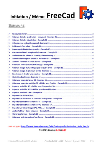
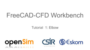
Background We aim to introduce the basic functionality ofthe CFD workbench on a simplistic pipeelbow with two inlets.The pipe flow benchmark problem is usuallymodelled in 2D. Unfortunately, the CFDworkbench is currently limited to 3D problemsonly. We will therefore model the problem asa thin sliver, where the front and back faceswill be treated with a slip condition.It is assumed that the user is familiar withFreeCAD geometry creation.OutletInlet 1Inlet 2
Elbow designPart Design
2Start a new sketchA certain familiarity with the sketchingenvironment within FreeCAD is expected. Formore information on sketching and part designsee:https://www.freecadweb.org/wiki/Sketcher tutorial134https://www.freecadweb.org/wiki/Basic Part Design Tutorial65
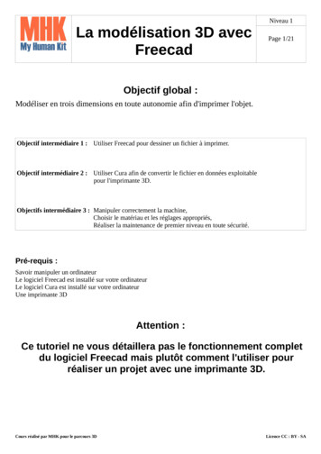
Sketch Create the sketch on the right, with the given setof dimensions.The sketch is easily created by first constructingthe primitives in the form of interconnected linesand arcs. Then use the various constraint tools toinsert horizontal, vertical, length and radiusconstraints where applicable.Nice tooltip descriptions of each function is shownby hovering the mouse pointer over any of theicons. The basic toolbars for sketch creation areBasic primitives toolbarConstraints toolbar
Pad the sketch Once the sketch has been completed,close the sketch creation.While still in the “Part Design” workbench,click on the “Pad” icon.Choose a length of 1m (1000mm) of TypeDimension.The pad function, takes a sketch andextrudes it in the 3rd direction.Click “Ok”
Fluid flowCase setup
Activate CFD workbench To activate the Cfd Workbench, click onthe dropdown menu in the taskbar, andselect “CfdOF”Once activated, the CFD task bar shouldappear.CFD Task bar:
New CFD analysis To create a new analysis, click on the“CFD” icon button (or by selecting“Analysis Container” from the “CFD” dropdown menu).Along with the “CfdAnalysis” object, thefollowing objects are automaticallycreated, with a set of default valuesassigned, which we will now go aboutmodifying for the simulation: PhysicsModelFluidPropertiesIntialiseFieldsOpenFOAM
Physics model selection The Physics Model Selection is where theuser specifies the desired simulation type.Upon creating a new analysis, defaultvalues is applied to the “PhysicsModel”object in the form of: Steady state, incompressible, laminar flow.The simulation types that are not yetsupported have been grayed out.For the current simulation we retain thedefault values as shown in the Figure.Click “OK” to save.
Select fluid properties Click on the material icon (or alternativelydouble click on “FluidProperties” object orselect “Add fluid properties” from the Cfddropdown menu).The mechanical material tab will appear.Properties can be set by either choosingan item from the predefined library, or bymanually entering the desired values.Choose “Air” from the predefined library.Click “OK” to saveNOTE: To change the units used by FreeCAD, or increase the number of significant figures that are displayed, see Edit- Preferences- Units
Initialise the internal flow variables The internal flow variables need to beinitialised prior to starting the simulation.Click on the initialise icon (or double clickon the “InitialiseFields” object or select“Initialise” from the CFD dropdown menu).Internal flow variables can be initialisedeither by using PotentialFoam, or byindividually entering the initial flowvariables.Select “Potential flow” for the currenttutorial.Click “OK” to save.orNOTE: Potential flow uses OpenFOAM’s PotentialFoam solver toautomatically initialise internal flow variables by solving a set ofincompressible, potential flow equations.
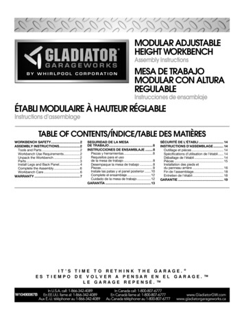
2Creating the mesh Highlight the 3D object “Pad” by clicking on it 1in the list of objects. This will activate themesh IconClick on the mesh Icon.In the Mesh task panel, choose ‘Gmsh’ as themeshing utility (for a tetrahedral mesh)Enter 800 mm as the max element sizecharacteristic length (as a start, you can makea more coarse mesh by setting it to 1500mm).Click on the “Mesh” button.TIP: When meshing, start with as coarse a mesh aspossible. Once a mesh has been successfully created,only then is it advised to refine the mesh. It can take avery long time to create highly refined meshes.NOTE: In the follow up tutorials, we will show how a meshwith different refinement regions can be generated. Fornow, we make use of a constant sized mesh.43
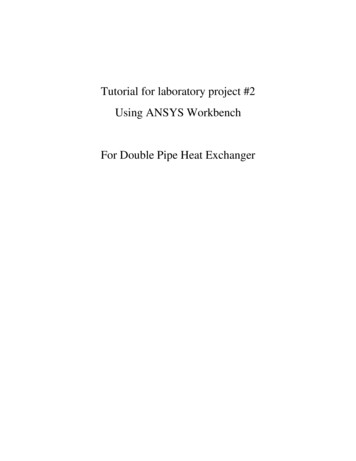
Adding boundary conditions: Inlet 1 To add a new boundary condition, click onthe boundary condition icon.Let’s add the first inlet boundary condition. Click on the first inlet face, and click“Add Face” button. Change “boundary” to “Inlet” Change “subtype” to “Uniform velocity” Specify cartesian velocity componentsto U (1m/s,0m/s,0m/s). (this can alsobe done by specifying “Magnitude andnormal”). Change the object name to “Inlet1”.The object name can be changed bypressing “F2” on the object list or byright clicking and choosing “Rename”.162453
Adding boundary conditions: Inlet 2 As with “Inlet1”, choose the correspondingface and click “Add face”.Choose Boundary: “Inlet”Choose Subtype: “Uniform velocity”Enter velocity corresponding toU (0m/s,3m/s,0m/s).Rename the object to “Inlet2”.Note: Inlet boundary conditions are colored blue.
Adding boundary conditions: Outlet Select the correct face, and click “Addface” button.Change Boundary: “Outlet”Change Subtype: “Static pressure”Set Pressure: 0 m/kg/s 2.Change object name to “Outlet”Note: Output faces are colored in red.Note: In incompressible simulations, pressure is treated as arelative value (‘gauge pressure’)
Adding boundary conditions: Pipe walls Add all the wall faces and set the walls as Boundary:“wall”, Subtype: “slip”Multiple faces can be added in one of two ways:1. Click on “Add face” without having selected anyfaces. All the faces can then one by one beadded. Once all the desired faces have beenselected, click “Add face” button again to deselectthe button.2. Multiple faces can be simultaneouslyhighlighted/selected by holding in the “Ctrl” buttonwhile clicking on multiple faces.Note: Walls are colored in dark grey.
Adding boundary conditions: Front and back slip Finally, we add the front and back faceboundary conditions.To emulate a 2D simulation in 3D, we setthe front and back faces to a “slip”boundary condition.Tip: Boundary faces that are not specified default to “slip”.
Final set of properties If correctly set up, CfdAnalysis should nowcontain the following set of items.To make sure all boundary conditions havebeen allocated correctly, as a final checkyou can hide all objects, and one by onemake each of the boundaries visible. Clickon the item and press “spacebar” orright-click, and select “toggle visibility”.We are now ready to run the CFDsimulation.
Solver control settings The solver settings can be modified by Highlighting the “OpenFOAM” object. At the bottom select the “Data” tab.The following settings can be modified Parallel: True/False Parallel Cores: If Parallel True, set the number ofcores to be used End Time: Steady state: Maximum number ofiterations Transient: End time Time Step: Time step size for transient simulations(default 1 for steady state, 0.001 for transient). Write Interval: How frequently information is storedto the hard drive for post processing. Convergence Criteria: default 1e-4.Note: Convergence criteria will not necessarily be achievable if transient flowstructures are present, which will result in residuals flattening out at a nonzerovalue. If in doubt, convergence of quantities being calculated (e.g. lift) shouldbe checked.
Write the case to a directory Click on the solver icon (or double click on“OpenFOAM” or select “Solver job control”from the CFD dropdown menu).“Working Directory” is the directory where thesimulation will be temporarily stored.WARNING: If the case within the directoryalready exists, it will be overridden.Click “Write” button.Depending on the mesh size, writing the casedirectory may take some time.If successful, the output message will state soaccordingly.The “Edit” button will open the case directoryfor manual editing.InitialIf successful
Running the CFD simulation If the case was successfully created, the“Run” button will become active.Clicking “Run” starts the simulation whichcan be terminated at any time by clicking“Stop”.A dynamic residual plot will be shown.The solver stops naturally once theconvergence criteria has been satisfied ormaximum number of iterations have beenreached. Default convergence criteria is1e-4 for Ux,Uy,Uz and pressure.To view the results, click the “Paraview”button.
Post-processing: ParaviewAn assortment ofpost-processing tools,such as plotting glyphs,streamlines,cross-section, contoursetc.What to plot,eg. U orpressure.Time stepto plotRefresh button: Ifsimulation is stillrunning, refresh to loadnew information as itbecomes available.For more information visit: http://www.paraview.org/Wiki/The ParaView Tutorial
Optional: Creating a 2D mesh Since we are modelling a 2D problem, we wouldlike to have a mesh with only one elementthrough the thicknessFirst delete the previous ‘slipWalls’ boundarycondition by right-clicking it in the tree view andselecting ‘Delete’Now create a boundary condition for the frontplane, selecting Boundary: ‘Constraint’ andSubtype: ‘2D bounding plane’For the back plane, create a second boundarycondition in the same wayNow, re-generate the mesh and re-run theanalysisNote: Currently, a full 3D mesh is first created and then extruded to form the2D mesh, so it is best to mesh a thin object to avoid spending too much timegenerating lots of unused cells
The End
FreeCAD geometry creation. Outlet Inlet 1 Inlet 2. Elbow design Part Design. Start a new sketch A certain familiarity with the sketching environment within FreeCAD is expected. For . NOTE: In the follow up tutorials, we will show how a mesh with different refinement regions can be generated. For now, we make use of a constant sized mesh.