Transcription
DocumentSAE J1939 — Protocol DescriptionJ1939KD41 CommunicationProtocolTable of Contents1General2Abbreviation index3CAN bus topology4Bit rate5Network management6CAN message format6.1 Parameter Group Number (PGN)7User Data formats7.1 Interpreting the transmittedpressure valuesKD418The default settings set9Settings PGN9.1 General information9.2 Exemplary register read access9.3 Unlocking the register write access9.4 Exemplary register write access10Register overview10.1 General CAN register10.2 General transducer registers10.3 Primary measuring channel settings10.4 Measurements-PGN 1 settings11Remarks12BibliographyTransmitterAll specifications are subject to change without notice.ashcroft.comAll sales subject to standard terms and conditions.info@ashcroft.com 2021 Ashcroft Inc. j1939 doc RevB 03-09-211.800.328.82581 of 13
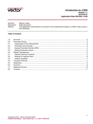
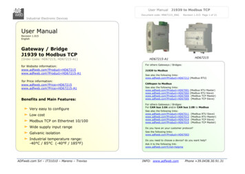
DocumentSAE J1939 — Protocol Description1 GeneralThe protocol SAE J1939 is based on CAN. The documents SAE J1939/1xdescribe its structure; Chapter 3 contains a general description.The Ashcroft KD41 is an ECU-type 1 pressure transducer and therefore does not include bus termination resistors.2Abbreviation indexCANController Area NetworkPGNParameter Group NumberDADestination AddressSASource AddressECUElectronic Control UnitSAESociety of Automotive EngineersPDUProtocol Data UnitSPNSuspect Parameter Number3 CAN bus topologyIn combination with the protocol SAEJ1939, the bus nodes are called ECUs.4SG2SG3CAN-Hi120ΩFor a limited extent, bus stubs may be used forrealizing a star topology. Be aware that in this case,the terminating resistors have to be adjusted.SG1120ΩThe CANbus is a linear structure (see Figure 1). Alldata is transferred in differential mode using twoelectrical lines (CAN high, CAN low). On both of itsends, the bus requires a termination network (eachresistor, 120Ω) to provide a defined idle state.CAN-LowFigure 1: Linear CAN bus topology with terminating resistors [1]Bit rateThe default bit rate is set to 125kBit/s. For special applications, different bit rates can be realized.All specifications are subject to change without notice.ashcroft.comAll sales subject to standard terms and conditions.info@ashcroft.com 2021 Ashcroft Inc. j1939 doc RevB 03-09-211.800.328.82582 of 13
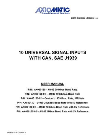
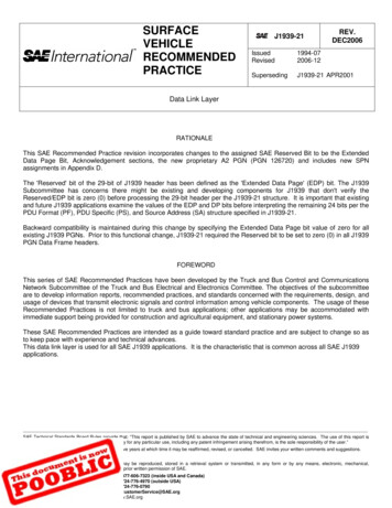
DocumentSAE J1939 — Protocol Description5 Network managementThe network management for SAE-J1939 is described in the document “J1939/81”. In default settings state,the pressure transducer fulfills the minimal requirements for “resolving address conflicts” and “checking formultiple device addresses”. Furthermore, it supports the automatic address alteration during runtime.The fields for a clear determination of the devices’ functions may be assigned according to the customer’s need6 CAN message formatFigure 2 depicts the CAN message format when using SAE J1939. The CANID contains message priority, PGN and source address.29 BIT CAN-IDENTIFIERDATA28 . 2625 . 87 . 0 bit0 . 8 bytePriorityPGN (Parameter Group Number)SA (Source Address)PDU (Protocol Data Unit)PGN252423 . 1615 . 8R (Reserved)DP (Data Page)PF (PDU Format)PS (PDU Specific)PDU1 FORMAT (specific) (peer to peer)I.23 . 1615 . 800h . EFh (0 . 239)DA (Destination Address)0 . 61439PDU2 FORMAT (global) (broadcast)or II.23 . 1615 . 8F0h . FFh (240 . 255)GE (Group Extension)61440 . 65535Figure 2: SAE J1939 CAN message format6.1 Parameter Group Number (PGN)The Parameter Group Number (PGN) consists of the fields “R” (Reserved), “DP” (Data Page),“PF” (PDU Format) and “PS” (PDU Specific). The first two fields (“R” and “DP”) are not used within the default parameter set and both do contain zeros. Document SAE J1939/71 defines various PGNs.Each of them has specifically structured payload and other parameters (e.g. repetition time).The usage of proprietary data formats is possible, as long as the field “PF” isassigned the values 239 (PGN Proprietary A) or 255 (PGN Proprietary B).All specifications are subject to change without notice.ashcroft.comAll sales subject to standard terms and conditions.info@ashcroft.com 2021 Ashcroft Inc. j1939 doc RevB 03-09-211.800.328.82583 of 13
DocumentSAE J1939 — Protocol Description6.1.1 PGN Proprietary AThis PGN is used when transferring data in a targeted manner. The field “PS” declares the destination address.6.1.2 PGN Proprietary BBroadcast messages use the PGN Proprietary B. In this case, the field“PS” declares supporting payload data formats.7 User Data formatsThe user data format must be interpreted according to the used PGN. A PGN may contain one or moreSPNs (Suspect Parameter Numbers). The SPN data structure is described by SAE J1939/71.The Ashcroft KD41 uses a proprietary data format as its default data format.7.1 Interpreting the transmitted pressure valuesEach message’s data field length is 8 bytes. The first two bytes contain the pressure value; the followingbytes are assigned 255 (0xFF). The MSB (Most Significant Byte) will be sent at first (known as Big Endian).Received data need to be multiplied with the Resolution. Subsequently, the Offset is subtracted.Both Resolution and Offset can be found in the pressure transducer’s datasheet.EXAMPLEPressure transducer:-1.10barResolution:0,01 bar / bitOffset:1 barPressure:9,00 barData bytes(HEX notation):0x03 0xE8 0xFF 0xFF 0xFF 0xFF 0xFF 0xFFRelevant data bytes:0x03 E8 1000decimalCalculation:Pressure PressureDigital Resolution Offsetbar 1000 0.01 bit 1 bar 9 barAll specifications are subject to change without notice.ashcroft.comAll sales subject to standard terms and conditions.info@ashcroft.com 2021 Ashcroft Inc. j1939 doc RevB 03-09-211.800.328.82584 of 13
DocumentSAE J1939 — Protocol Description8 The default settings setThe following table shows a default configuration. Specific configurations andsettings may be found in part-number depending product datasheets.PARAMETERDEFAULT VALUEMEANINGTransmission baud rate125 kBit/sTransmission speed.Start address208 (0xD0)Assigned address at boot up time.PGN65330 (0xFF 32)Parameter number of data.Priority7Message priority (0 highest).Transmission cycle time(also repetition time)100msRepetition time of the pressure messages.SPNAccording to pressure range.Describes data interpretation.Manufacturer ID455 (0x01 C7)Manufacturer ID of AshcroftNAGANO GmbHECU Instance1Function Instance3Function4Industry Group5Vehicle System7Vehicle System Instance1Arbitrary Address Capable1These fields hold the device’sfunction within the system.Automatic address obtaining enabled.9 Settings PGN9.1 General informationThe Settings PGN can be used to read and write registers from the KD41 pressure transducer. These registers may contain settings or status/informational data, depending on the address that is being accessed.There are two types of accesses: reading and writing accesses. While writing accesses mustbe unlocked before using, read accesses can always be applied (refer to section 9.1.2).A typical Settings PGN access consists of three important things: The CAN-ID holding the address of the J1939 device that is being accessed, Register Access Code (containing one read/write bit and the 15-bit register address; discussed below), In case of write access: The payload data that shall be written (up to six bytes). Theamount of payload data bytes (and thus the DLC) depends on the register being written to. Important: All multi-byte values need to be ordered as Little Endian!All specifications are subject to change without notice.ashcroft.comAll sales subject to standard terms and conditions.info@ashcroft.com 2021 Ashcroft Inc. j1939 doc RevB 03-09-211.800.328.82585 of 13
DocumentSAE J1939 — Protocol DescriptionThe figure below shows how to assemble the necessary CAN-ID:MSBLSB5 bits8 bitsInfo field.Typically “0x18”8 bits8 bitsDestination Address(see below)Must be “0xEF”Source AddressThe field Destination Address contains the address of the device being accessed.When choosing the value 0xFF combined with subsequent register write accesses, all present KD41 pressure transducers devices will be configured.The 16-bit Register Access Code consists (as already mentioned above) of two fields:1 A one-bit read/write value located at the most significant bit. The value ‘1’stands for writing; the value ‘0’ stands for reading access.2 The 15-bit address of the register being accessed. An overview of all available registers can be found at section 9.2Two more important things: Before writing values to any register, the write access must be unlocked.In order to unlock write access, refer to section 9.1.2. Data written to any registers will not automatically be applied tonon-volatile EEPROM. Thus, the save process must be performed afterapplying configuration values. The save procedure is described in section 9.2.2.1.9.1.1 Typical register read accessThe following figure shows how to build up a CAN message containing a valid read access.CAN-ID (hex)DLC18EFFFAB2Register Access Code (Little Endian!)01Data Bytes (hex)02Typical access for reading a value from register 0x0201.A possible response to this access could be as follows:CAN-ID (hex)DLC18EFABxx8Register Access Code01xx stands for thetransducer’s addressRead value (in this case int32; Little Endian)02Data Bytes (hex)DDCCBBAATypical response to reading a value from register 0x0201.The amount of data bytes contained in the response depends on the register that wasaccessed. Refer to the overview of available registers, located at section 9.2.All specifications are subject to change without notice.ashcroft.comAll sales subject to standard terms and conditions.info@ashcroft.com 2021 Ashcroft Inc. j1939 doc RevB 03-09-211.800.328.82586 of 13
DocumentSAE J1939 — Protocol Description9.1.2 Unlocking the register write accessBefore writing to any registers, the write access must be unlocked. The following CAN message holds the necessary data in order to unlock all present Ashcroft J1939 transducers.CAN-ID (hex)DLC18EFFFAB8Data Bytes (hex)Unlock code41445A2B504D5354Unlocking register write access for all present Ashcroft J1939 transducers.After transferring the message above, each present Ashcroft J1939 transducer sends out the message below.CAN-ID (hex)DLC18EFFFABxx8Data Bytes (hex)Unlock code41445A2B504D5354Each transducers’ response after successfully unlockingxx stands for thetransducer’s addressAfter performing this procedure, all present transducers’ register write access will be unlockeduntil reboot. Alternatively, the access can be manually locked by writing to register 0x0000.9.1.3 Typical register write accessRequirement: The register write access has already been unlocked (refer to 9.1.2).The amount of data bytes (and data values) depends on the register that is being accessed.The following CAN message shows how to write exemplary data contents to register 0x0201.Register Access Code (Little Endian; MSB is ‘1’)CAN-ID (hex)DLC18EFFFAB6Data value (in this case int32; Little Endian)Data Bytes (hex)0182DDCCBBAATypical access for reading a value from register 0x0201.In case the data values were assembled correctly and write access isunlocked, the transducer transfers the following message.CAN-ID (hex)DLC18EFABxx3Register Access Code01xx stands for thetransducer’s addressReturn code (0x00 means “success”)82Data Bytes (hex)00CCBBAATypical response to reading a value from register 0x0201.After performing all necessary write accesses, the user might want to save the appliedsettings to non-volatile EEPROM. Section 9.2.2.1 shows how to do so.All specifications are subject to change without notice.ashcroft.comAll sales subject to standard terms and conditions.info@ashcroft.com 2021 Ashcroft Inc. j1939 doc RevB 03-09-211.800.328.82587 of 13
DocumentSAE J1939 — Protocol Description9.2 Register OverviewThe following sections describe the accessible entries of the Ashcroft KD41 register set.15-bit Registeraddress (HEX)Allowed access typesDescriptionGeneral CAN registers0x0000WLocks all further write accesses to any registers0x0001RTransducers hardware revision.0x0002RTransducers firmware revision.0x0010RWMeasurements’ endianness0x0020RWJ1939 start address0x0040WBootup baudrate0x0050RWMilliseconds timestamp – Upper 32 bits0x0051RWMilliseconds timestamp – Lower 32 bits. Access at first!General transducer registers0x0100WSave current settings to EEPROM0x0110WReset to factory settings0x0120WPerform rebootPrimary measuring channel settings0x0200RWGain (Float32)0x0201RWGain (Int32)0x0210RWOffset (Float32)0x0211RWOffset (Int32)0x0220WApply current readings as ‘zero’RW‘Zero’ value0x0221Measurements-PGN 1 settings0x0800RWGeneral PGN settings0x0810RWStatic mask 10x0811RWStatic mask 20x0820RWMapping entries 10x0821RWMapping entries 2All specifications are subject to change without notice.ashcroft.comAll sales subject to standard terms and conditions.info@ashcroft.com 2021 Ashcroft Inc. j1939 doc RevB 03-09-211.800.328.82588 of 13
DocumentSAE J1939 — Protocol Description9.2.1 General CAN registers9.2.1.1 0x0001, 0x0002 (Transducer hardware/firmware revision)These read-only registers hold the hardware/firmware revision (each Uint16). The returned decimal values areencoded in the following manner: YYWWwhere YY corresponds to the year, WW to the week.9.2.1.2 0x0010 (Measurements’ endianness)This register changes the endianness of all measurement values.Type of data valueUint8Possible valuesNote0x00: Little Endian0x01: Big Endian0x00 . 0x019.2.1.3 0x0020 (J1939 start address)This register allows the access the current J1939 start address used for address claiming process.The amount of data values differs when reading/writing – that’s why both access types will be discussed separately.Read access:Type of data valuePossible valuesUint80x00 . 0xFDNoteContains the start addressWrite access:Type of data valuePossible valuesUint80x00 . 0xFDContains the start addressNoteUint80x00 or 0x01Makes (if 0x01) the transducer performaddress claiming immediately after writing9.2.1.4 0x040 (Start-up baudrate)This register changes the baudrate at bootup. A change of this register does not change the baudrate immediately.Type of data valueUint8Possible values0x01 . 0x08Note0x01: 20 kBit/s0x02: 50 kBit/s0x03: 100 kBit/s0x04: 125 kBit/s0x05: 250 kBit/s0x06: 500 kBit/s0x07: 800 kBit/s0x08: 1 MBit/s9.2.1.5 0x0050 / 0x0051 (Milliseconds timestamp)These registers are incremented every millisecond automatically and they can be mapped to a PGN.Note, it is possible to transmit timestamps and process values together. After power on the register will be initialized with 0. Register 0x0050 held the upper 32 bit of the 64bit timestamp.With a write access it is possible to synchronize the timestamp to a higher ranking system.NOTE: For read / write access to these registers it is highly recommended to access register 0x0051 at first.All specifications are subject to change without notice.ashcroft.comAll sales subject to standard terms and conditions.info@ashcroft.com 2021 Ashcroft Inc. j1939 doc RevB 03-09-211.800.328.82589 of 13
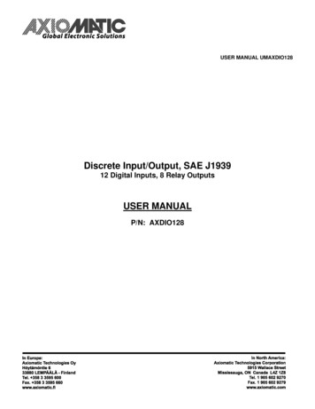
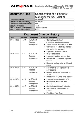
DocumentSAE J1939 — Protocol Description9.2.2 General transducer registers9.2.2.1 0x0100 (Save current settings to EEPROM)Access to this register saves all settings to EEPROM and make them available through a reset of the transducer.9.2.2.2 0x0110 (Reset to factory settings)Access to this register reset all setting to the factory defaults.9.2.2.3 0x0120 (Perform reboot)Access to this register perform a reboot of the transducer. All changes which are not save will be lost.9.2.3 Primary measuring channel settings9.2.3.1 0x0200 0x0219 (Gain and offset parameters)These registers enable the user to manipulate the output values’ scalingsettings. The following image shows the linear scaling procedure.Field Value0 . 20000xOffsetGainyProcess Valuefloat32J1939 outputThe transducer’s nominal measuring range corresponds to the internal Field Value range of [0 20000]. Usingthe gain and offset parameters, these internal values are being scaled according to the following formula:y Gain x Offsetwith x Field Valuey Process ValueBoth gain and offset parameters can be read and written as Int32 or Float32 data types.9.2.3.2 0x0220 (Apply current reading as ‘zero’)An access to this register start an offset compensation. The actual reading will be used as offset reading.9.2.3.3 0x0221 (‘zero’ value)This register held the actual ballue for the offset compensation.Type of data valuePossible valuesInt16-32768.32767NoteValue for offset compensationAll specifications are subject to change without notice.ashcroft.comAll sales subject to standard terms and conditions.info@ashcroft.com 2021 Ashcroft Inc. j1939 doc RevB 03-09-211.800.328.825810 of 13
DocumentSAE J1939 — Protocol Description9.2.4 Measurements-PGN 1 settingsThe following sub-sections explain all necessary registers enabling the user to confugure measurements-PGN9.2.4.1 0x0800 (General PGN settings)This register allows to access general settingss of measurements-PGN 1. The register contentsconsist of 6 data bytes; the following table shows how to assemble the register contents.Type of data valuePossible valuesNoteUint8PDU FormatUint8PDU SpecificUint16PGN transmission rate in milliseconds.Uint8Split up 4 4 bits: The uppermost 4 bits containspriority (possible values 0x0.0x7) The lowermost 4 bits contain the PGNData Page (“DP”).0x0 DP 0; 0x1 DP 1Uint8Splits up to 4 4 bits: The uppermost 4 bits contain the flagAutostartEnabled (0x8 Enabled). The lowermost 4 bits contain thePGN Data Length Code (“DLC”).9.2.4.2 0x0810 0x0811 (Static mask)These register held values which are copied to the PGN message before a transmission is started. The intention is to applied static values to a message. The values are overwritten from the Mapping entries. Refer section 9.2.4.3 for an example.Register 0x0810 (Format: Little Endian)CAN-ID (hex)DLCxxxxxxxRegister 0x0811 (Format: Little Endian)Data Bytes (hex)xxxxxxxxxxxxxxxxAssignment static mask bytes vs PGN-messgeAll specifications are subject to change without notice.ashcroft.comAll sales subject to standard terms and conditions.info@ashcroft.com 2021 Ashcroft Inc. j1939 doc RevB 03-09-211.800.328.825811 of 13
DocumentSAE J1939 — Protocol Description9.2.4.3 0x0820 0x0821 (Mapping entries)The intention of these register is to design the structure of the PGN which is send.The possible data and there identification number is listed in the table below.VALUESIZEUSAGE0Uint8Data of this Position is not overwritten1Uint8Status of transducer2Uint32LSB of Timestamp in Millisecond3Uint64Timestamp in millisecond5Uint32Ashcroft – serial number without “Z”6Uint64Ashcroft – serial number without “Z”7Uint8 Uint3211Uint32user serial number12Uint64user serial number40Int16Field value primary channel41Int16Process value primary channel42Int32Process value primary channel43Float32Process value primary channel50Int16Field value primary channel51Int16Process value secondary channel52Int32Process value secondary channel53Float32Process value secondary channelAshcroft – serial number with “Z”The assignment between the registers and the PGN is shown below.Register 0x0810 (Format: Little Endian)CAN-ID (hex)DLCxxxxxxxRegister 0x0811 (Format: Little Endian)Data Bytes (hex)xxxxxxxxxxxxxxxxAssignment mapping bytes vs PGN-messgeThe internal order of assigning a PGN – message is: Allocating a buffer with 8 Byte Coping the static mask to the buffer Coping the values to the PGN correspondent the mapping registers. If themapping has the value 0 the equivalent byte of the PGN is not changed.Note: If the mapped data is greater than Uint8 the followedmapping Bytes must be set to 0 to prevent an overwriting of the DataAll specifications are subject to change without notice.ashcroft.comAll sales subject to standard terms and conditions.info@ashcroft.com 2021 Ashcroft Inc. j1939 doc RevB 03-09-211.800.328.825812 of 13
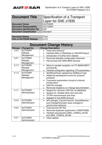
DocumentSAE J1939 — Protocol DescriptionExample:Process value primary channel Int16CAN-ID (hex)DLCxxxxxxxuser serial number Uint32Data Bytes (hex)xxxxxxxxAABBxxxxAssignment mapping bytes vs PGN-messgeTo design the structure of the shown message the mapping and static mask register have following values:REGISTERStatic mask 1 (0x0810)VALUE0xBBAAFFFFStatic mask 2 (0x0811)0xFFFFFFFFMapping entries 1 (0x0820)0x0000002AMapping entries 2 (0x0821)0x0000000B10 RemarksThe behaviour described in this document corresponds with the internal standard ofAshcroft Inc.It is possible to alter the behaviour according to the customer’s needs, sothat the pressure transducer may be installed easily to the target application.11 Bibliography[1] Stefan-Xp, “Wikimedia Commons (CC BY-SA 3.0),” 24 Nov. 2016. [Online].Available: https://commons.wikimedia.org/w/index.php?curid 3607670.All specifications are subject to change without notice.ashcroft.comAll sales subject to standard terms and conditions.info@ashcroft.com 2021 Ashcroft Inc. j1939 doc RevB 03-09-211.800.328.825813 of 13
in the default parameter set and both do contain zeros. Document SAE J1939/71 defines various PGNs. Each of them has specifically structured payload and other parameters (e.g. repetition time). The usage of proprietary data formats is possible, as long as the field "PF" is assigned the values 239 (PGN Proprietary A) or 255 (PGN Proprietary B).