Transcription
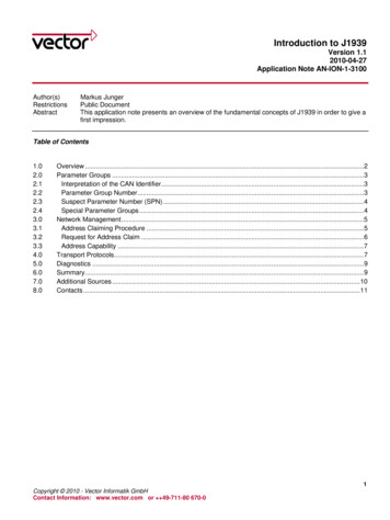
Introduction to J1939Version 1.12010-04-27Application Note AN-ION-1-3100Author(s)RestrictionsAbstractMarkus JungerPublic DocumentThis application note presents an overview of the fundamental concepts of J1939 in order to give afirst impression.Table of 8.0Overview .2Parameter Groups .3Interpretation of the CAN Identifier.3Parameter Group Number.3Suspect Parameter Number (SPN).4Special Parameter Groups .4Network Management.5Address Claiming Procedure .5Request for Address Claim .6Address Capability .7Transport Protocols.7Diagnostics .9Summary.9Additional Sources .10Contacts .111Copyright 2010 - Vector Informatik GmbHContact Information: www.vector.com or 49-711-80 670-0
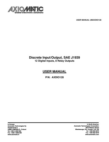
Introduction to J19391.0 OverviewSAE J1939 is used in the commercial vehicle area for communication in the commercial vehicle. In this applicationnote, the properties of SAE J1939 should be described in brief.SAE J1939 uses CAN (Controller Area Network, ISO11998) as physical layer. It is a recommended practice thatdefines which and how the data is communicated between the Electronic Control Units (ECU) within a vehiclenetwork. Typical controllers are the Engine, Brake, Transmission, etc.Figure 1: Typical J1939 vehicle networkThe particular characteristics of J1939 are: Extended CAN identifier (29 bit)Bit rate 250 kbit/sPeer-to-peer and broadcast communicationTransport protocols for up to 1785 data bytesNetwork managementDefinition of parameter groups for commercial vehicles and othersManufacturer specific parameter groups are supportedDiagnostics featuresThere exist several standards which are derived from SAE J1939. These standards use the basic features of SAEJ1939 with a different set of parameter groups and modified physical layers. These standards are:ISO11783 – Tractors and machinery for agriculture and forestry – Serial control an communicationDefines the communication between tractor and implements on an implement bus. It specifies some services onapplication layer, like Virtual Terminal, Tractor ECU, Task Controller and File Server. It adds an ExtendedTransport Protocol and Working Set Management.NMEA2000 – Serial-data networking of marine electronic devicesIt defines parameter groups for the communication between marine devices. It specifies the additional Fast Packettransport protocol.ISO11992 – Interchange of digital information between towing and towed vehicleSpecifies the interchange of information between road vehicle and towed vehicle. It uses same parameter groupformat as J1939 on a different physical layer with 125 kbit/s.FMS – Fleet Management SystemThe FMS standard defines a gateway between the J1939 vehicle network and a fleet management system.2Application Note AN-ION-1-3100
Introduction to J19392.0 Parameter GroupsA parameter group is a set of parameters belonging to the same topic and sharing the same transmission rate. Thedefinition of the application relevant parameter groups and parameters can be found in application layer document[9].The length of a parameter group is not limited to the length of a CAN frame. Usually a parameter group has aminimum length of 8 bytes up to 1785 bytes. Parameter groups with more than 8 bytes require a transport protocolfor transmission.2.1 Interpretation of the CAN IdentifierThe CAN identifier of a J1939 message contains Parameter Group Number (PGN), source address, priority, datapage bit, extended data page bit and a target address (only for a peer-to-peer PG).The identifier is composed as follows:PriorityExtendedData PageData PagePDUFormatPDUSpecificSourceAddress3 bit1 bit1 bit8 bit8 bit8 bit With PDU format 240 (peer-to-peer), PDU specific contains the target address. Global (255) can also beused as target address. Then the parameter group is aimed at all devices. In this case, the PGN is formedonly from PDU format.With PDU format 240 (broadcast), PDU format together with the Group Extension in the PDU specificfield forms the PGN of the transmitted parameter group.2.2 Parameter Group NumberEach parameter group is addressed via a unique number – the PGN. For the PGN a 24 bit value is used that iscomposed of the 6 bits set to 0, PDU Format (8 bits), PDU Specific (8 bits), Data Page (1 bit) and Extended DataPage (1 bit).There are two types of Parameter Group Numbers: Global PGNs identify parameter groups that are sent to all (broadcast). Here the PDU Format, PDUSpecific, Data Page and Extended Data Page are used for identification of the corresponding ParameterGroup. On global PGNs the PDU Format is 240 or greater and the PDU Specific field is a GroupExtension. Specific PGNs are for parameter groups that are sent to particular devices (peer-to-peer). Here the PDUFormat, Data Page and Extended Data Pare are used for identification of the corresponding ParameterGroup. The PDU Format is 239 or less and the PDU Specific field is set to 0.3Application Note AN-ION-1-3100
Introduction to J1939With this breakdown of the PGN, 240 (16 * 256) 4336 different parameter groups within each data page arepossible. With the transmission of a parameter group, the PGN is coded in the CAN identifier.With the Data Page bit and Extended Data Page bit 4 different data pages can be selected, see following table.Extended DataPage BitData Page Bit00SAE J1939 Page 0 Parameter Groups01SAE J1939 Page 1 Parameter Groups (NMEA2000 )10SAE J1939 reserved11ISO 15765-3 definedDescriptionTable 1: Data PagesSample of a parameter group definition:Name:Transmission rate:Data length:Extended Data PageData page:PDU format:PDU specific:Default priority:PG Number:Engine temperature 1 – ET11s8 bytes00254238665,262 (00FEEE16)Description of data:Byte: 123,45,678Engine Coolant TemperatureEngine Fuel Temperature 1Engine Oil Temperature 1Engine Turbocharger Oil TemperatureEngine Intercooler TemperatureEngine Intercooler Thermostat Opening2.3 Suspect Parameter Number (SPN)A suspect parameter number is assigned to each parameter of a parameter group or component. It is used fordiagnostic purpose to report and identify abnormal operation of a Controller Application (CA).The SPN is a 19 bit number and has a range from 0 to 524287. For proprietary parameters a range from 520192 to524287 is reserved.2.4 Special Parameter GroupsSAE J1939-21 defines some parameter groups on the data link layer:Request parameter groupThe request parameter group (RQST, PGN 00EA0016) can be sent to all or a specific CA to request a specifiedparameter group. The RQST contains the PGN of the request parameter group. If the receiver of a specific requestcannot respond, it must send a negative acknowledgment. The RQST has a data length code of 3 bytes and is theonly parameter group with a data length code less than 8 bytes.Acknowledgement parameter groupThe acknowledgement parameter group (ACKM, PGN 00E80016) can be use to send a negative or positiveacknowledgment, i.e. in response to a request.4Application Note AN-ION-1-3100
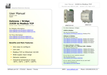
Introduction to J1939Address claiming parameter groupThe address claiming parameter group (ACL, PGN 00EE0016) is used for network management, see chapter 3.0.Commanded address parameter groupThe commanded address parameter group (CA, PGN 00FED816) can be used to change the address of a CA.Transport protocol parameter groupThe transport protocol parameter groups (TPCM, PGN 00EC0016 and TPDT, PGN 00EB0016) are used to transferparameter groups with more than 8 data bytes, see chapter 4.0.3.0 Network ManagementThe software of an Electronic Control Unit (ECU) is the Controller Application (CA). An ECU may contain one ormore CAs. Each CA has a unique address and an associated device name.Each message that is sent by a CA contains this source address. There are 255 possible addresses: 0.2530.127 and 248.253128.247254255– Valid source addresses for CAs– Used for CAs with Preferred Addresses and defined functions– Available for all CAs– Null– GlobalMost CAs like Engine, Gearbox, etc. have a preferred address (see [2]). Before a CA may use an address, it mustregister itself on the bus. This procedure is called "address claiming." Thereby the device sends an "AddressClaim" parameter group (ACL, PGN 00EE0016) with the desired source address. This PG contains a 64-bit devicename. If an address is already used by another CA, then the CA whose device name has the higher priority hasclaimed the address.The device name contains some information about the CA and describes its main function. A manufacturer codemust be requested by the SAE. The values of the fields are defined in SAE J1939-81 [11].Figure 2: Device name data of the address claim parameter group3.1 Address Claiming ProcedureIn a common situation the controller application sends an Address Claim parameter group at start up and waits adefined amount of time. If it does not detect an address conflict it can start with its normal communication.5Application Note AN-ION-1-3100
Introduction to J1939Figure 3: Address claiming procedureIn a situation where another CA already uses the address an address conflict occurs. The CA with the higherpriority of the device name will obtain the address. The other CA must send a “Cannot Claim Address” parametergroup, with source address Null (254).Figure 4: Address claiming procedure with address conflictIt depends on the address capability of a CA how to proceed, if an address cannot be obtained.3.2 Request for Address ClaimA CA can detect other CAs in the network by requesting the ACL parameter group. It is allowed to use the NullAddress (254) as source address before a CA has performed the address claiming procedure. If the request isaddressed to the Global address (255) all CAs in the network must respond with the ACL parameter group(including own CA if an address has been claimed already).6Application Note AN-ION-1-3100
Introduction to J1939Figure 5: Request address claim3.3 Address CapabilitySAE J1939-81 defines the following types of capability to obtain an address:Arbitrary address capable CAThe CA selects it source address by internal algorithm. It is able to select a new address on an address conflict.The Arbitrary Address Capable field in the device name indicates this capability.Single address capable CAA CA of this type can use only one address. On address conflicts it is not able to select another address. It cansupport the commanded address parameter group or proprietary mechanisms to change the address. TheArbitrary Address Capable field is not set for these CAs.4.0 Transport ProtocolsParameter groups that contain more than 8 data bytes are transmitted by means of a transport protocol.Figure 6: Transport ProtocolFor peer-to-peer and broadcast transmission, there are two different protocols. The transport protocols utilize twospecial parameter groups which are used for the connection management (TP.CM) and the transmission of thedata (TP.DT).For broadcast transmission, the BAM (Broadcast Announce Message) protocol is used. Here, after a BAM-PG, thetransmitter sends all data PGs at a minimum interval of 50ms.7Application Note AN-ION-1-3100
Introduction to J1939Figure 7: BAM transmissionWith the peer-to-peer transmission, the transmitter initiates the connection with a "request to send" message. Thereceiver then controls the transport protocol with "clear to send" and finally acknowledge it with "end of messageacknowledge."Figure 8: RTS/CTS transmission8Application Note AN-ION-1-3100
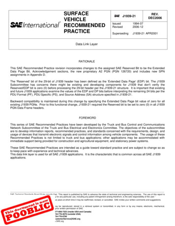
Introduction to J19395.0 DiagnosticsThe diagnostic features of SAE J1939 supports following services: Reporting and identification of abnormal operationMemory accessMonitored testsAn important parameter group is the Diagnostics Message 1 (DM1, PGN FECA16). If supported, it shall be sentcyclic by each CA to report its state. The parameter group contains the state for different lamps: Malfunction Indicator LampRed Stop LampAmber Warning LampProtect LampAn instrument cluster can use this information to report the state of the system to the driver.Additionally the parameter group contains a list of Diagnostic Trouble Codes (DTC). Together with the address of asender the parameter of misbehaving components can be identified.Figure 9: Diagnostic Trouble CodeA DTC contains 4 bytes, which contain the SPN, the Failure Mode Identifier (FMI) and an Occurrence Count. If theDM1 contains more than one DTC a transport protocol must be used.6.0 SummaryWith the specification of the parameter groups, CAN identifier scheme, and the network management, amanufacturer-spanning cooperation of control units will be ensured.J1939 describes, in addition to the mechanisms presented here, the physical properties and use of bus subsegments.9Application Note AN-ION-1-3100
Introduction to J19397.0 Additional SourcesSAE Documents[1]SAE J1939Recommended Practice for a Serial Control and Communications Vehicle Network[2]SAE J1939-01 Recommended Practice for Control and Communications Network for On-HighwayEquipment[3]SAE J1939-02 Agricultural and Forestry Off-Road Machinery Control and Communication Network[4]SAE J1939-03 On Board Diagnostics Implementation Guide[5]SAE J1939-05 Marine Stern Drive and Inboard Spark-Ignition Engine On-Board DiagnosticsImplementation Guide[6]SAE J1939-11 Physical Layer - 250k bits/s, Twisted Shielded Pair[7]SAE J1939-13 Off-Board Diagnostic Connector[8]SAE J1939-14 Physical Layer, 500k bits/s[9]SAE J1939-15 Reduced Physical Layer, 250K bits/sec, Un-Shielded Twisted Pair (UTP)[10]SAE J1939-21 Data Link Layer[11]SAE J1939-31 Network Layer[12]SAE J1939-71 Vehicle Application Layer[13]SAE J1939-73 Application Layer - Diagnostics[14]SAE J1939-74 Application - Configurable Messaging[15]SAE J1939-75 Application Layer - Generator Sets and Industrial[16]SAE J1939-81 Network Management[17]SAE J1939-82 Compliance - Truck and Bus[18]SAE J1939-84 OBD Communications Compliance Test Cases for Heavy Duty Components and Vehicles10Application Note AN-ION-1-3100
Introduction to J19398.0 ContactsGermanyand all countries not named below:Vector Informatik GmbHIngersheimer Str. 2470499 StuttgartGERMANYPhone: 49 711-80670-0Fax: 49 711-80670-111E-mail: info@de.vector.comFrance, Belgium, Luxemburg:United Kingdom, Ireland:Vector GB Ltd.RhodiumCentral BoulevardBlythe Valley ParkSolihull, BirminghamWest Midlands B90 8ASUNITED KINGDOMPhone: 44 121 50681-50E-mail: info@uk.vector.comChina:Vector Informatik GmbHShanghai Representative OfficeSuite 605, Tower C,Everbright Convention CenterNo. 70 Caobao RoadXuhui DistrictShanghai 200235P.R. CHINAPhone: 86 21 - 6432 5353 ext. 0Fax: 86 21 - 6432 5308E-mail: info@vector-china.comIndia:Vector Informatik India Private Ltd.4/1/1/1 Sutar IconSus RoadPashanPune 411021INDIAPhone: 91 9673 336575E-mail: info@vector-india.comUSA, Canada, Mexico:Vector CANtech, Inc.39500 Orchard Hill Pl., Ste 550Novi, MI 48375USAPhone: 1 248 449 9290Fax: 1 248 449 9704E-mail: info@us.vector.comJapan:Vector Japan Co. Ltd.Seafort Square Center Bld. 18F2-3-12, Higashi-shinagawa,Shinagawa-kuTokyo 140-0002JAPANPhone: 81 3 5769 7800Fax: 81 3 5769 6975E-mail: info@jp.vector.comKorea:Vector Korea IT Inc.#1406, Mario Tower,222-12 Guro-dong, Guro-guSeoul, 152-848REPUBLIC OF KOREAPhone: 82 2 807 0600Fax: 82 2 807 0601E-mail: info@kr.vector.comVector France SAS168 Boulevard Camélinat92240 MalakoffFRANCEPhone: 33 1 42 31 40 00Fax: 33 1 42 31 40 09E-mail: information@fr.vector.comSweden, Denmark, Norway,Finland, Iceland:VecScan ABTheres Svenssons Gata 941755 GöteborgSWEDENPhone: 46 31 764 76 00Fax: 46 31 764 76 19E-mail: info@se.vector.com11Application Note AN-ION-1-3100
Introduction to J1939 2 Application Note AN-ION-1-3100 1.0 Overview SAE J1939 is used in the commercial vehicle area for communication in the commercial vehicle. In this application note, the properties of SAE J1939 should be described in brief. SAE J1939 uses CAN (Controller Area Network, ISO11998) as physical layer. It is a recommended .