Transcription
USER MANUAL UMAX0301x010 UNIVERSAL SIGNAL INPUTSWITH CAN, SAE J1939USER MANUALP/N: AX030120 - J1939 250kbps Baud RateP/N: AX030120-01 – J1939 500kbits/s Baud RateP/N: AX030120-02 – Custom J1939 Baud Rate, 1Mbits/sP/N: AX030130 – J1939 250kbps Baud Rate with 5V ReferenceP/N: AX030130-01 – J1939 500kbps Baud Rate with 5V ReferenceP/N: AX030130-02 – J1939 1Mbps Baud Rate with 5V ReferenceUMAX0301x0 Version 2
VERSION HISTORYVersion1.0.1.--1.0.2--DateOct. 4, 2013Oct. 21, 2013Oct. 25, 2013Oct. 31, 2013Jan. 24, 2014AuthorIlona KorpelainenAmanda WilkinsAmanda WilkinsIlona KorpelainenAmanda Wilkins--May 22, 2014Amanda Wilkins1.0.31.0.4Nov. 25, 2014Feb. 11, 2015Ilona KorpelainenAntti Keränen--Feb. 17, 2015Antti Keränen1.0.5Jul. 3, 2015Antti Keränen-August 21,2015January 25,2016March 7, 2016September 1,2016February 15,2018Amanda WilkinsModoficationInitial DraftMarketing ReviewAX030120Updated screen capturesAdded quiescent current and inputsampling rateTech Specs - connection of groundsinternally added.ECU ID and Component ID PNGs addedTable naming (tables 17,18&19) on page29 updated, Over voltage setpointdefaults updated. Note of maximum pulsecount frequency added on page 8.P/Ns AX030120-01 and AX030120-02added. P/N table added to page 6. EAconfiguration note added to page 22.Added note concerning Inputs 4, 5, 9 and10 accuracy in Frequency and PWMmeasurements to page 9.Updated EA versionAmanda WilkinsAdded vibration compliance and CE markIlona KorpelainenAmanda WilkinsUpdated to reflect firmware version 3.00Added input impedance and scan rate toTechnical Specs.New Input Types added, CAN Input andOutput signals’ configuration setpointsupdated. Firmware upgrade instructionupdated.Added part number AX030130 (-01, -02)details to user manual1.0.61.0.71.0.82February 10,2020UMAX0301x0 Version 2Antti KeränenGustavo Del Valle
ACCRONYMSACKPositive Acknowledgement (from SAE J1939 standard)BATT /-Battery positive (a.k.a. Vps) or Battery Negative (a.k.a. GND)DINDigital Input used to measure active high or low signalsDMDiagnostic Message (from SAE J1939 standard)DTCDiagnostic Trouble Code (from SAE J1939 standard)EAElectronic Assistant , p/n AX070502 (A Service Tool for Axiomatic ECUs)ECUElectronic Control Unit (from SAE J1939 standard)GNDGround reference (a.k.a. BATT-)I/OInputs and OutputsMAPMemory Access ProtocolNAKNegative Acknowledgement (from SAE J1939 standard)PDU1A format for messages that are to be sent to a destination address, either specific orglobal (from SAE J1939 standard)PDU2A format used to send information that has been labeled using the Group Extensiontechnique, and does not contain a destination address.PGNParameter Group Number (from SAE J1939 standard)PropAMessage that uses the Proprietary A PGN for peer-to-peer communicationPropBMessage that uses a Proprietary B PGN for broadcast communicationPWMPulse Width ModulationRPMRotations per MinuteSPNSuspect Parameter Number (from SAE J1939 standard)TPTransport ProtocolUINUniversal input used to measure voltage, current, frequency or digital inputsVpsVoltage Power Supply (a.k.a. BATT )%dcPercent Duty Cycle (Measured from a PWM input)UMAX0301x0 Version 2
TABLE OF CONTENTS1.OVERVIEW OF CONTROLLER . 71.1.Input Function Blocks . 71.2.Input filtering . 111.3.Diagnostic Function Blocks . 111.7.1.CAN Transmit Message Setpoints . 181.7.2.CAN Transmit Signal Setpoints . 191.9.2.INSTALLATION INSTRUCTIONS . 232.1.3.4.5.Available Control Sources . 20Dimensions and Pinout . 232.1.1.AX030120 Dimensions . 232.1.2.AX030130 Dimensions . 242.1.3.Connector Pinout for AX030120 and AX030130 . 25OVERVIEW OF J1939 FEATURES . 263.1.Introduction to Supported Messages . 263.2.NAME, Address and Identification Information . 27ECU SETPOINTS ACCESSED WITH ELECTRONIC ASSISTANT . 304.1.Accessing the ECU Using EA . 304.2.J1939 Setpoints . 314.3.Input Setpoints . 324.4.Constant Data List . 334.5.Lookup Table . 344.6.Programmable Logic. 364.7.Math Function Block . 384.8.CAN Transmit Setpoints . 404.9.CAN Receive Setpoints . 424.10.General Diagnostics Options . 434.11.Diagnostics Blocks. 44REFLASHING OVER CAN WITH EA BOOTLOADER . 47APPENDIX A - TECHNICAL SPECIFICATION.A-1UMAX0301x0 Version 2
Table 1 – Universal Input Type Options . 8Table 2 - Input Sensor types effect on other setpoints . 8Table 3 – Debounce Time Options . 9Table 4 - Software Debounce Filter Times . 9Table 5 – Pullup/Pulldown Resistor Options . 10Table 6 – Active High/Low Options . 10Table 7 – Digital Input Sensor Type versus Input State . 10Table 8 – Pulse Counter Sensor Type versus Input State . 10Table 9 – Lamp Set by Event in DM1 Options . 14Table 10 – FMI for Event Options. 14Table 11 – Low Fault FMIs and corresponding High Fault FMIs . 15Table 12 – X-Axis Type Options . 15Table 13 – PointN – Response Options . 16Table 14 – Table X – Condition Y, Operator Options . 17Table 15 – Table X – Conditions Logical Operator Options . 17Table 16 – Math function X Operator Options . 18Table 17 – Available Control Sources and Numbers . 21Table 18 - AX030120 & AX030130 Connector Pinout . 25Table 19 – J1939 Setpoints . 31Table 20 - Input Setpoints . 32Table 21 – Lookup Table Setpoints . 35Table 22 – Programmable Logic Setpoints . 37Table 23 – Math Function Setpoints . 39Table 24 – CAN Transmit Message Setpoints . 41Table 25 – CAN Receive Setpoints . 42Table 26 – General Diagnostics Options Setpoints. 43Table 27 – Diagnostic Block Setpoints . 46UMAX0301x0 Version 2
REFERENCESJ1939Recommended Practice for a Serial Control and Communications VehicleNetwork, SAE, April 2011J1939/21Data Link Layer, SAE, December 2010J1939/71Vehicle Application Layer, SAE, March 2011J1939/73Application Layer-Diagnostics, SAE, February 2010J1939/81Network Management, SAE, May 2003TDAX030120Technical Datasheet, 10 Universal Signal Input with CAN, AxiomaticTechnologies 2016TDAX030130Technical Datasheet, 10 Universal Signal Input with CAN and 5V reference,Axiomatic Technologies 2019UMAX07050xUser Manual V4.10.77, Electronic Assistant and USB-CAN, AxiomaticTechnologies, July 2014This document assumes the reader is familiar with the SAE J1939 standard. Terminologyfrom the standard is used, but not described in this document.NOTE: This product is supported by Electronic Assistant V4.10.77.0 and higherUMAX0301x0 Version 2
1. OVERVIEW OF CONTROLLERThe 10 Analog Input electronic control unit (ECU) is a device that measures inputs and sends thedata to an SAE J1939 CAN network. Its flexible circuit design gives the user a wide range ofconfigurable input types. The sophisticated control algorithms allow the user to program thecontroller for a wide range of applications without the need for custom software.The Axiomatic Electronic Assistant is used to configure the 10 Analog Inputs ECU. Programmingconfigurable properties, EA setpoints, are listed in chapter 4. Setpoint configuration can be saved ina file which can then be utilized to program the same configuration to another 10 Analog Inputcontroller. Throughout this document EA setpoint names are referred with bolded text in doublequotes and the setpoint option is referred with italicized text in single-quotes. For example, “InputSensor Type” setpoint set to option ‘Voltage 0 to 5V’.In this document the configurable properties of the ECU are divided into function blocks, namelyInput Function Block, Diagnostic Function Block, Lookup Table Function Block, Programmable LogicFunction Block, Math Function Block, CAN Transmit Message Function Block and CAN ReceiveMessage Function Block. Input function block includes properties used to select input sensorfunctionality. Diagnostic function block properties are used to configure fault detection and reactionfunctionalities. The math function block gives user an opportunity to process inputs with basicmathematical of logical functions. And the CAN transmit message function block configuresproperties of the messages sent to the CAN bus. These function blocks are presented in detail innext subchapters.The 10 Analog Input ECU can be ordered using the following part numbers depending on 130AX030130-01AX030130-021.1.ECU with the default J1939 baud rate (250kbits/s).ECU with the 500kbits/s J1939 baud rate.ECU with a custom 1Mbits/s J1939 baud rate.ECU with the default J1939 baud rate (250kbits/s) and 5V Reference.ECU with the 500kbits/s J1939 baud rate and 5V Reference.ECU with a custom 1Mbits/s J1939 baud rate and 5V Reference.Input Function BlocksThe controller has ten fully programmable universal inputs that can be setup to read: voltage, current,PWM, frequency, or digital input signals. The “Input Sensor Type” setpoint is used to configureinput type. Selecting input type effects on other setpoints and how they are interpreted and shouldthus be selected first on this block. The input sensor types are listed in Table 1.UMAX0301x0 Version 2.7 - 53
0121320214041425051606162707172DisabledVoltage 0 to 5 VVoltage 0 to 10 VCurrent 0 to 20 mACurrent 4 to 20 mAFrequency 0.5 to 50 HzFrequency 10 Hz to 1 kHzFrequency 100 Hz to 10 kHzPWM Low Frequency ( 1kHz)PWM High Frequency ( 100Hz)Digital (normal)Digital (inverse)Digital (latched)CounterPulse CounterPulse Counter (both edges)Table 1 – Universal Input Type OptionsVoltage (i.e. 0-5V, 0-10V) or Current (0-20mA, 4-20mA) inputs go directly to a 12-bit analog-to-digitalconverter (ADC) on the processor. A voltage input is a high impedance input protected against shortsto GND or Vcc. In current mode, a 250Ω resistor is used to measure the input signal. Analog Inputsshould be connected to the Analog GND reference pins provided on the connector, per Table 18.Input Sensor TypeDisabledVoltage 0 to 5 VVoltage 0 to 10 VCurrent 0 to 20 mACurrent 4 to 20 mAFrequency 0.5 to 50 HzErrorThresholdunitsN/AVVmAmAHz(RPM)Frequency 10 Hz to 1 kHzHz(RPM)Frequency 100 Hz to 10 kHzHz(RPM)PWM Low Frequency ( 1kHz)PWM High Frequency ( 100Hz)Digital (normal)Digital (inverse)Digital (latched)CounterPulse CounterPulse Counter (both edges)%dc%dcN/AN/AN/AN/AN/AN/ATransmit dataresolutionTransmit dataoffset unitsN/A0.001 V/Bit0.001 V/Bit0.1 mA/Bit0.1 mA/Bit1 Hz/Bit(RPM/Bit)1 Hz/Bit(RPM/Bit)1 Hz/Bit(RPM/Bit)0.1 %dc/Bit0.1 %dc/Bit1 State/Bit1 State/Bit1 State/Bit1 Pulse(s)/Bit1 Pulse(s)/Bit1 tePulse(s)Pulse(s)Pulse(s)Table 2 - Input Sensor types effect on other setpointsUMAX0301x0 Version 2.8 - 53
Frequency/RPM or Pulse Width Modulated (PWM) inputs are connected to 16-bit timer pins on theprocessor. “Debounce Time” setpoint is used to select an input capture filter for the timer pin inquestion.0123None111ns1.78us14.22usTable 3 – Debounce Time OptionsAn additional software debounce filter can be used with Digital Input types for filtering the inputsusing longer time constants than with the default debounce filter. The available softwareimplemented debounce times are listed in Table e 4 - Software Debounce Filter TimesThe “Pulse Per Revolution” setpoint is only associated with the frequency input type. If a non-zeroPulse/Rev is selected, then the input data will be reported as in rotations-per-minute (RPM).Otherwise, frequency inputs are measured in Hertz.NOTE: The input channels 4, 5, 9 and 10 have limited accuracy when used fordetecting edges (Frequency / PWM measurements). The measurement accuracycan be enhanced using software filtering, but in case the Frequency or PWM dutycycle measurements need to have high accuracy, please avoid using these fourchannels.The Counter input sensor type implements input pulse timing feature. “Measuring Window” setpointdefines number of pulses to be timed. Pulses in the input signal are calculated and the time passeduntil the number of pulses has been received is timed. Once the count has been reached, the timeis transferred as input signal measurement result and the calculation is started again.NOTE: The Counter inputs work up to 5kHz with 1% accuracy. Higher input frequenciesmay result in accuracy degrading of the detected edge count.There are three digital “Input Sensor Type” options: Normal, Inverse and Latched. With digital inputsensor types, the input measurement is given, either 1 (ON) or 0 (OFF). Input voltage is measuredwith 3V threshold.UMAX0301x0 Version 2.9 - 53
On Frequency, PWM and digital input modes 10kΩ pull-up or pull-down resistors can be enabled ordisabled by setting the value of the “Pullup/Pulldown Resistor” setpoint. Setpoint options are givenin Table 5. By default pull-down resistors are enabled for all inputs.0 Pullup/down Off1 10 kΩ Pullup2 10 kΩ PulldownTable 5 – Pullup/Pulldown Resistor Options“Active High/Active Low” setpoint is used to configure how signal high and low are interpreted.Setpoint options are given in Table 6. By default all inputs are selected to be Active High, whichmeans that signal high is interpreted as 1(ON) and signal low as 0(OFF).0 Active High1 Active LowTable 6 – Active High/Low OptionsTable 7 shows the effect of different digital input types on input signal measurement interpretationwith recommended “Pullup/Pulldown Resistor” and “Active High/Low” combinations.Input Sensor Type6Digital (normal)61Digital (inverse)62Digital (latched)PulldownActive HighHighLow or OpenHigh or OpenLowHigh to LowLow to HighPullupActive LowLow or OpenHighLowHigh or OpenLow to HighHigh to LowInput measured (state)1 (ON)0 (OFF)1 (ON)0 (OFF)0 (no change)1 (state change)Table 7 – Digital Input Sensor Type versus Input StateInput Sensor Type70Counter71Pulse Counter72Pulse Counter(both edges)FunctionCount pulses in the specified time window (defined usingMeasuring Window setpoint)Count pulses (only rising edges). Maximum number beforewrapping back to zero can be defined using Max PulseCount setpoint.Count pulses (both rising and falling edges). Maximumnumber before wrapping back to zero can be defined usingMax Pulse Count setpoint.Table 8 – Pulse Counter Sensor Type versus Input StateTable 8 describes the Pulse Counter Input types available. The main difference between the‘Counter’ and ‘Pulse Counter’ types is that ‘Counter’ measures the time (defined using “MeasuringWindow”) which is needed to count the specified number of pulses. The ‘Pulse Counter’ modescount pulses (using edge detection), independent of time (max count is defined using “Max PulseCount”).UMAX0301x0 Version 2.10 - 53
The “Minimum Range” and “Maximum Range” setpoints are used to define range of the signalinput outputs as a control source. For example, if “Maximum Range” is set to 4V for an input, thecontrol signal is saturated at 4V if input signal rises above 4V. The “Minimum Range” and“Maximum Range” setpoints are interpreted in input types units, thus they should be re-adjustedafter editing “Input Sensor Type”.Software filters can be applied to the measured input signal. Setpoints “Software Filter Type” and“Software Filter Constant” are used to configure the software filter. By default, no filter is appliedto the signal. Software filtering is described in detail in next section.1.2.Input filteringMeasured input data from universal inputs can be filtered to form desired CAN message data. Inputfilters are configured with “Filter Type” and “Filter Constant” setpoints. Filters are configured foreach input individually.“Filter Type” setpoint defines the type of software filter used. Setpoint options are ‘No Filtering’,‘Moving Average’ and ‘Repeating Average’. The ‘No Filtering’ option applies no filtering to themeasured input data. The ‘Moving Average option applies the transfer function below to themeasured input data, where ValueN is the current value of the CAN message data, ValueN-1 is theprevious CAN message data and Filter Constant is the value of the “Filter Constant setpoint”.Equation 1 - Moving Average Transfer Function:ValueN ValueN-1 Input- ValueN-1Filter ConstantEquation 2 - Repeating Average Transfer Function:Value N0 InputNNThe ‘Repeating Average’ option applies the transfer function above to the measured input data,where N is value of the “Filter Constant” setpoint. At every reading of the input value, the value isadded to the sum. At every Nth read, the sum is divided by N, and the result is new CAN messagedata. The sum is set to zero for the next read and summing is started again.1.3.Diagnostic Function BlocksThe 10 Analog Input Controller supports diagnostic messaging. DM1 message is a message,containing Active Diagnostic Trouble Codes (DTC) that is sent to the J1939 network in case a faulthas been detected. A Diagnostic Trouble Code is defined by the J1939 standard as a four-byte value.UMAX0301x0 Version 2.11 - 53
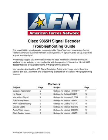
In addition to supporting the DM1 message, the following are supported:SPNFMICMOCDM2DM3DM11Suspect Parameter Number(user defined)Failure Mode Identifier(see Table 10 and Table 11)Conversion Method(always set to 0)Occurrence Count(number of times the fault has happened)Previously Active Diagnostic Trouble CodesSent only on requestDiagnostic Data Clear/Reset of Previously Active DTCs Done only on requestDiagnostic Data Clear/Reset for Active DTCsDone only on requestFault detection and reaction is a standalone functionality that can be configured to monitor and reportdiagnostics of various controller parameters. The 10 Analog Input Controller supports 16 DiagnosticsDefinitions, each freely configurable by the user.By default, the monitoring of operating voltage, CPU temperature and receive message timeouts isconfigured to diagnostics blocks 1, 2 and 3., In case any of these three diagnostics blocks are neededfor some other use, the default settings can be adjusted by the user to suit the application.There are 4 fault types that can be used, “Minimum and maximum error”, “Absolute value error”,“State error” and “Double minimum and maximum error”.Minimum and maximum error has two thresholds, “MIN Shutdown” and “MAX Shutdown” that haveconfigurable, independent diagnostics parameters (SPN, FMI, Generate DTCs, delay before flaggingstatus). In case the parameter to monitor stays between these two thresholds, the diagnostic is notflagged.Absolute value error has one configurable threshold with configurable parameters. In case theparameter to monitor stays below this threshold, the diagnostic is not flagged.State error is similar to the Absolute value error, the only difference is that State error does not allowthe user to specify specific threshold values; thresholds ‘1’ and ‘0’ are used instead. This is ideal formonitoring state information, such as received message timeouts.Double minimum and maximum error lets user to specify four thresholds, each with independentdiagnostic parameters. The diagnostic status and threshold values is determined and expected asshow in Figure 1 below.UMAX0301x0 Version 2.12 - 53
Figure 1 – Double Minimum and Maximum Error ThresholdsThere is also built in error status flags for power supply and CPU temperature monitoring. In caseany of the diagnostics blocks is measuring these two parameters, the corresponding internal errorstatus flags can be used for shutting down the unit in case of failure. The setpoints “Power FaultDisables Outputs” and “Over Temperature Shutdown” can be used for enabling the shutdown ofthe unit (shutdown output driving is turned off).While there are no active DTCs, the 10 Analog Input Controller will send “No Active Faults” message.If a previously inactive DTC becomes active, a DM1 will be sent immediately to reflect this. As soonas the last active DTC goes inactive, a DM1 indicating that there are no more active DTCs will besent.If there is more than one active DTC at any given time, the regular DM1 message will be sent usinga multipacket message to the Requester Address using the Transport Protocol (TP).At power up, the DM1 message will not be broadcasted until after 5 second delay.This is done to prevent any power up or initialization conditions from being flagged asan active error on the network.When the fault is linked to a DTC, a non-volatile log of the occurrence count (OC) is kept. As soonas the controller detects a new (previously inactive) fault, it will start decrementing the “Delay beforeEvent is flagged” timer for that Diagnostic function block. If the fault has remained present duringthe delay time, then the controller will set the DTC to active, and will increment the OC in the log. ADM1 will immediately be generated that includes the new DTC. The timer is provided so thatintermittent faults do not overwhelm the network as the fault comes and goes, since a DM1 messagewould be sent every time the fault shows up or goes away.By default, the fault flag is cleared when error condition that has caused it goes away. The DTC ismade Previously Active and is it is no longer included in the DM1 message. To identify a fault havinghappened, even if the condition that has caused is one away, the “Event Cleared only by DM11”UMAX0301x0 Version 2.13 - 53
setpoint can be set to ‘True’. This configuration enables DTC to stay Active, even after the fault flaghas been cleared, and be included in DM1 message until a Diagnostic Data Clear/Reset for ActiveDTCs (DM11) has been requested.As defined by J1939 Standard the first byte of the DM1 message reflects the Lamp status. “LampSet by Event” setpoint determines the lamp type set in this byte of DTC. “Lamp Set by Event”setpoint options are listed in Table 9. By default, the ‘Amber, Warning’ lamp is typically the one setbe any active fault.0123ProtectAmber WarningRed StopMalfunctionTable 9 – Lamp Set by Event in DM1 Options“SPN for Event” defines suspect parameter number used as part of DTC. The default value zero isnot allowed by the standard, thus no DM will be sent unless “SPN for Event” in is configured to bedifferent from zero. It is user’s responsibility to select SPN that will not violate J1939 standard.When the “SPN for Event” is changed, the OC of the associated error log is automatically reset tozero.012345678910111213141516171819202131Data Valid But Above Normal Operational Range - Most Severe LevelData Valid But Below Normal Operational Range - Most Severe LevelData IntermittentVoltage Above Normal, Or Shorted To High SourceVoltage Below Normal, Or Shorted To Low SourceCurrent Below Normal Or Open CircuitCurrent Above Normal Or Grounded CircuitMechanical ErrorAbnormal Frequency Or Pulse Width Or PeriodAbnormal Update RateAbnormal Rate Of ChangeRoot Cause Not KnownBad ComponentOut Of CalibrationSpecial InstructionsData Valid But Above Normal Operating Range – Least Severe LevelData Valid But Above Normal Operating Range – Moderately Severe LevelData Valid But Below Normal Operating Range – Least Severe LevelData Valid But Below Normal Operating Range – Moderately Severe LevelNetwork ErrorData Drifted HighData Drifted LowCondition ExistsTable 10 – FMI for Event OptionsUMAX0301x0 Version 2.14 - 53
Every fault has associated a default FMI with them. The used FMI can be configured with “FMI forEvent” setpoint, presented in Table 10. When an FMI is selected from Low Fault FMIs in Table 11for a fault that can be flagged either high or low occurrence, it is recommended that the user wouldselect the high occurrence FMI from the right column of Table 11. There is no automatic setting ofHigh and Low FMIs in the firmware, the user can configure th
J1939/21 Data Link Layer, SAE, December 2010 J1939/71 Vehicle Application Layer, SAE, March 2011 J1939/73 Application Layer-Diagnostics, SAE, February 2010 J1939/81 Network Management, SAE, May 2003 TDAX030120 Technical Datasheet, 10 Universal Signal Input with CAN, Axiomatic Technologies 2016 .