Transcription
Advanced Enviro-Septic (AES)Wastewater SystemDesign & Installation ManualThe onsite wastewater systemsweeping the industry
(AES) - Advanced Enviro-Septic Systems Designand Installation ManualPreview 2011 RJCPurposeThe purpose of this manual is to provide guidance in the design and installationof septic leaching systems using the Presby Environmental, Inc., group ofproducts.PresbyEnvironmental,Inc., standardsAll systems using Advanced Enviro-Septic products must be designed andinstalled in compliance with the procedures and specifications described in thismanual.StateVWDQGDUGV Advanced Enviro-Septic when used as directed meets all the standards forDomestic use in the subsurface disposal of wastewater.In this manualThis manual contains the following subjects.SectionA – IntroductionB – Definitions of TermsC – Design CriteriaD – Installation, Handling, and Storage GuidelinesE – Sand and Fill RequirementsF – Single Level System ConfigurationsG – Multi-LevelTM System ConfigurationsH – Non-Conventional System ConfigurationsI – Pump System RequirementsJ – Venting RequirementsK – Bottom Drain RequirementsL – Simple-Septic Leaching SystemsM – System Rejuvenation and ExpansionPage2478111225303233353637Use ofattachmentrequiredThis manual requires the use of an attachment specific to your State orProvince in order to properly design and install Advanced Enviro-Septic systems.TechnicalsupportAction Tanks Industries, provides technical support to all individuals using PresbyEnvironmental products. For questions about products or the information contained inthis manual, please contact us at 07-544242421
Section AIntroductionBackgroundLiquid that exits from a septic tank (effluent) contains suspended solids thatcan cause other types of septic systems to fail prematurely. Solids canoverload bacteria, cut off aeration required for bacterial activity, and/or seal theunderlying soil.Our uniquesystemcomponentsThe Advanced Enviro-Septic System is a product consisting of threecomponents.What oursystem doesBy utilizing simple, yet effective, natural processes the Advanced EnviroSeptic System treats septic tank effluent in a manner that prevents solidsfrom entering surrounding soils, increases system aeration, and provides agreater bacterial area (mat) than traditional systems.1. A corrugated, perforated, high-density plastic pipe with a unique series ofridges on the peak of each corrugation and plastic “skimmers” extendinginto the pipe’s interior.2. A thick mat of randomly oriented plastic fibers surrounding the pipe.3. A special non-woven geo-textile plastic fabric around the mat of fibers.Why our system The Advanced Enviro-Septic System retains solids in its pipe and providesexcelsmultiple bacterial surfaces to treat effluent prior to its contact with the soil.The continual cycling of effluent (the rising and falling of liquid inside thepipe) enhances bacterial growth. No other leaching system design offers thisfunctionality. Our systems excel because they are more efficient, last longer,and have a minimal environmental impact.SystemadvantagesHere’s a brief list of the advantages of The Advanced Enviro-Septic System . Costs less than traditional installation products and materialsRequires a smaller areaEliminates “septic mounds” through sloping system installationsAdapts to difficult sitesRequires less fillInstalls more easily and quickly than traditional systemsEliminates the need for expensive washed stoneAdapts easily to both commercial and residential sitesUses a protected receiving surfaceIncreases system performance and longevityTests environmentally safer than conventional systemsRecharges groundwater more safely than conventional systemsContinued2
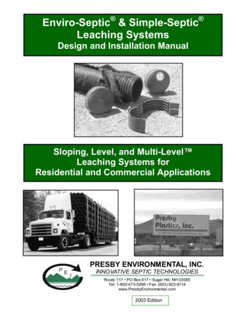
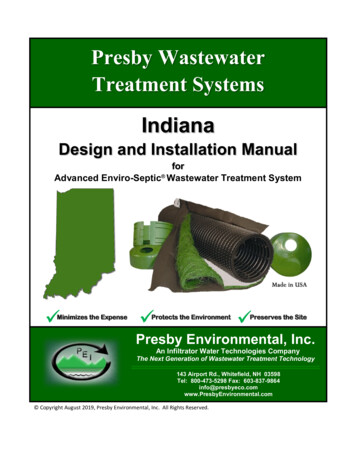
Introduction, ContinuedHere’s a cross sectional diagram of Advanced Enviro-Septic System pipe.What it lookslikeTOP SOIL6 GEO-TEXTILE FABRIC5 COARSE FIBERSSEWN SEAM3 SKIMMERS97 8AIR SPACE2SCUM1EFFLUENT24 RIDGESSLUDGECORRUGATED PLASTIC PIPEWITH EXTERIOR RIDGESSANDORIGINAL SOILHow it worksThese are the basic stages that take effect in the Advanced Enviro-Septic SystemStageWhat Happens1Warm effluent enters the pipe and is cooled to ground temperature.2Suspended solids separate from the cooled liquid effluent.3 Skimmers further capture grease and suspended solids from the effluent as it exits through perforations in the pipe.Pipe ridges allow the effluent to flow uninterrupted around the4circumference of the pipe and aid in cooling.A mat of random, coarse fibers separates more suspended solids5from the effluent.Effluent passes into the geo-textile fabric and grows a protected6bacterial surface.Sand wicks the liquid from the geo-textile fabric and enables air to7transfer to the bacterial surface.Fabric and fibers provide a large bacterial surface to break down8solids.An ample air supply and fluctuating liquid levels increase bacterial9efficiency.3
Section BDefinitions of TermsIntroductionAs you read through the information in this manual, you will encountercommon terms, terms that are common to our industry, and terms that areunique to Advanced Enviro-Septic (AES) systems. While alternative definitions LV PD\ H[LVW WKsection defines these terms as they are used in this manual.List of termsHere’s a list of the terms defined in this section. Basic system Bottom drain Center-to-center spacing Combination system Coupling Design flow D-box Differential venting Distribution box Distribution box manifold Double offset adapter Drain sump Drop connection End cap Enviro-Septic pipe Equalizer LPD High and Low Oxygen Demand Vent (ODV) High flow Level system Line Low flow Multi-Level system Offset adapter Raised connectionSectionSerial distributionSimple-Septic pipeSloping systemBasic systemA is a system consisting of one section of Advanced Enviro-Septic pipe.Bottom drainA bottom drain is a pipe connecting the end of a line to a drain sump.Continued4
Definitions of Terms, ContinuedCenter-to-center Center-to-center spacing is the horizontal distance from the center of one linespacingto the center of the adjacent line.CombinationsystemA combination system is a system incorporating two or more sections ofEnviro-Septic pipe, each section receiving effluent from a distribution box.CouplingA coupling is a fitting that joins two pieces of Advanced Enviro-Septic pipe.D-BoxD-Box is an abbreviation for distribution box.Design flowDesign flow is the determined LPD flow as dictated by State and/or local codeor rule.DifferentialventingDifferential venting is a method of venting an Advanced Enviro-Septic systemutilizing high and low vents.(Oxygen Demand port)Distribution box A distribution box is a device used to divide and/or control effluent flow.Distribution box A distribution box manifold is a method of joining any number of distributionmanifoldbox outlets to a single pipe.Double offsetadapterA double offset adapter is an end cap with two offset holes.Drain sumpA drain sump is a watertight chamber connected to the end of a bottom drainline.Drop connection A drop connection is a PVC pipe arrangement used to connect different levelsof Advanced Enviro-Septic pipe used in Multi-LevelTM systems.End capAn end cap is a solid cap used to seal the end of an Advanced Enviro-Septic pipe.Enviro-Septic pipeAn Advanced Enviro-Septic pipe is a single unit of pipe, 3m in length withan outside diameter of 300mm and a storage capacity of approximately 220 litres.Equalizer An Equalizer is a plastic insert installed in the outlet lines of a distributionbox to provide more equal effluent distribution to each outlet.LPDLPD is an abbreviation for litres per day.Continued5
Definitions of Terms, ContinuedHigh and lowvents 2'9High and low 2'9 vents are pipes used in differential venting.High flowHigh flow is the minimum “design flow” requiring combination or distributionbox system designs.Level systemA level system is a system in which lines of Advanced Enviro-Septic areinstalled at the same elevation.LineA line is a number of Advanced Enviro-Septic pipes connected by couplingswith an offset adapter on the inlet end and an offset adapter or end cap on theopposite end.Low flowLow flow is any “design flow” lower than “high flow.”Multi-LevelsystemTMA Multi-LevelTM system is a patented system consisting of at least two levelsof Advanced Enviro-Septic pipe separated by sand.Offset adapterAn offset adapter is an end cap fitted with a 100mm offset hole at the12 o’clock position.Presby Maze A Presby Maze is a plastic unit that traps suspended solids and pre-treatsseptic tank effluent inside a septic tank.RaisedconnectionA raised connection is a PVC pipe arrangement used to connect lines ofAdvanced Enviro-Septic pipe to maintain the correct liquid level inside each line.SectionA section is a group of Advanced Enviro-Septic lines in serial distributionreceiving effluent from a distribution box in a combination system.SerialdistributionA serial distribution is a group of Advanced Enviro-Septic lines* connected witha raised and/or drop connection.*See “line” in this section.Simple-Septic pipeA Simple-Septic pipe is a product identical to Advanced Enviro-Septic with theexception of the thick mat of randomly orientated plastic fibers between thecorrugated plastic pipe and the geo-textile fabric.Sloping systemA sloping system is a system in which lines of Advanced Enviro-Septic areinstalled atdifferent elevations.6
Section CDesign CriteriaIntroductionThis page discusses general design criteria.Line orientation Advanced Enviro-Septic lines must be laid level and should run parallel tocontours (perpendicular to sloping terrain) if possible.Longer linespreferableIn general, fewer long lines are preferable to a greater number of short lines.Longer lines provide more efficient settling of solids. In addition, longer morenarrow systems reduce the potential for ground water mounding.Minimum/maxi- To maintain efficient effluent cycling, the minimum length of an Advanced Enviromum lineSeptic line should be 9m and the maximum length 30m. In some instanceslengthssite conditions may require shorter or longer lengths.Reference: See Section H, “Non-Conventional System Configurations.”3 meterIt is easier for the installer if systems are designed in 3m increments sinceincrements work Advanced Enviro-Septic pipe is 3m in length. However, the pipe is easily cut tobestany length necessary with a sharp knife.Line elevationsFor sloping systems it is helpful to provide elevations on the design for eachline of the system.Septic tank and The outlet of a septic tank or D-Box must be set at least 50mm above the highestD-Box elevations inlet of the Advanced Enviro-Septic line.Depth and types While most installations should avoid a cover depth of more than 450mm, someof coverconditions will require exceeding this limit. In particular, Advanced Enviro-Septic systems with paved cover and/or vehicular traffic require a minimum of 450mm ofcover along with appropriate venting.Reference: See Section J, “Venting Requirements.”Provide notesDesigners should add homeowner notes to their designs regarding system usefor homeowners and maintenance. Notes should include topics such as abusive substances,additives, constant discharge, etc. Suggested tank pumping and inspectionschedules would also be beneficial.See StaterequirementsLocal and State jurisdictions may require additional design specifications.7
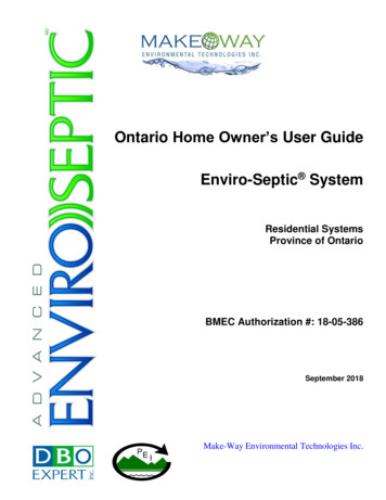
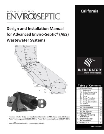
Section DInstallation, Handling, and Storage GuidelinesIntroductionThis page contains guidelines that must be observed while installing, handling,and storing Enviro-Septic products.Site preparation Here are some site preparation guidelines. Remove topsoil, roots, and organic matter under the required sand area of aproposed system, including the slope extensions of raised systems.Maintain the existing characteristics of the underlying soil as much aspossible.Add the sand fill on the same day that the leach area is excavated.Do not allow water to run into or over the system during construction.Do not work wet or frozen soils.Do not smear or compact soils while preparing site.Note: It is not necessary for the leach area to be smooth when the site isprepared.SystemcomponentsHere’s a picture of the Enviro-Septic components.Contamination Note: Keep mud, grease, oil, etc., from all system components.Avoid dragging pipe through wet or muddy areas.Continued8
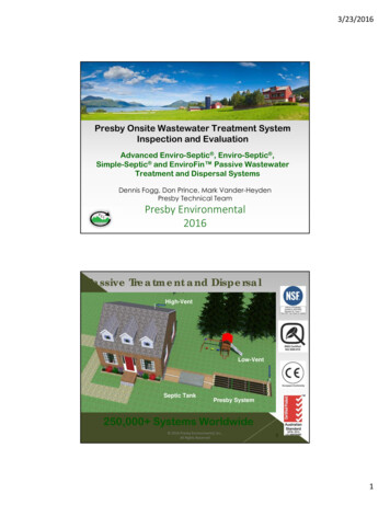
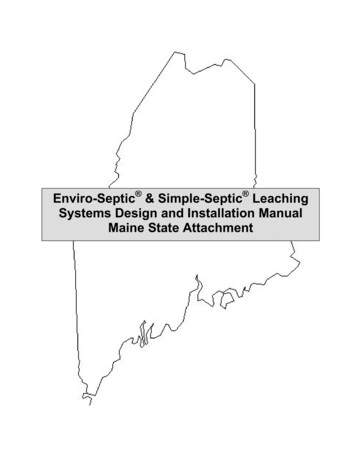
Installation, Handling, and Storage Guidelines, ContinuedRaised connections consist of offset adapters, 100mm PVC pipe and pipe elbows.They enable greater liquid storage capacity and increase the bacterial surfacesbeing developed. Use raised connections to connect lines of Enviro-Septic pipe. Here is a diagram along with some installation notes.Use raisedconnectionsInstallation Notes:1. Insert PVC pipe no more than 100mm into the offsetadapter to prevent air locking.2. Install the raised connection so that the top of the90 bend is level with the top of the offset adapter.3. Pack sand under and around the raised connectionto prevent movement.OFFSETHOLETOP VIEWSIDE VIEWENVIRO-SEPTIC PIPEEND VIEWLEVEL90 PVC Bend PP PVC PipeOFFSET ADAPTERMAX. 4"OFFSET ADAPTER4" PVC Pipe90 PVC BendWhile sand may be used to keep pipe in place while covering, simple toolsmay also be constructed for this purpose. Here are two examples. One ismade from rebar, the other from wood.Line spacersWooden frameWelded Rebar handleBent RebarPipeCaution: Remove all tools used as line spacers before final covering.Continued9
Installation, Handling, and Storage Guidelines, ContinuedSoil compactionMinimize machine movement to avoid soil compaction and destruction of thesoil structure under and around the system. Be especially careful not tocompact soil on the down slope side of the system.Backfilling andfinal gradingSpread a minimum of 150mm of system sand over the pipe. Spread the remainingfill. Final grading should shed water away from the system.Note: A tracked vehicle may be used to spread the system sand and topsoil aslong as it maintains at least 300mm of cover over the pipe.Erosion controlProtect the site from erosion by proper grading, mulching, seeding, and controlof runoff.StorageThe outer fabric of the Advanced Enviro-Septic pipe is ultra-violet stabilized.However, the protection breaks down after a period of time in direct sunlight.To preventdamage to the fabric, cover the pipe with an opaque tarp.Store pipe on high and dry areas to prevent surface water and soil fromentering the pipes or contaminating the fabric prior to installation.10
Section ESand and Fill RequirementsIntroductionThis page describes the sand and fill requirements for the Advanced Enviro-Septic Leaching System.System sandAll configurations of Advanced Enviro-Septic require a minimum of 6” of systemsand surrounding the circumference of the pipe. This sand, typically gravelly coarsesand, must adhere to the following percentage and quality restrictions.Percentage Restrictions35% or less of the total sand may be gravel.40%-90% of the total sand is to be coarse and very coarse sand.Gravel Quality RestrictionsNo gravel is to exceed ¾” in diameter.No gravel is smaller than 2mm/.0787” in diameter.Coarse Sand Quality RestrictionsNo coarse sand is smaller than 0.5mm/.0196” in diameter.Fines Quality RestrictionsNo more than 2% of the total sand may pass through a 75 µm sieve.ASTM Standard: C-33 (concrete sand) meets the above requirements.Sand fill andclean fillSand fill is the material used to surround the system sand.Note: System sand may also be used as sand fill.Clean fill is the material used to complete the system.Raised systemfill extensionsRaised systems require fill extensions.Perimeter sandrequirementsSystems sloping 10% or less require the system sand and sand fill area toextend a minimum of 300mm around the perimeter of the Enviro-Septic pipe.Reference: See “Raised systems fill extensions” in your State attachment.Systems sloping greater than 10% require the system sand and sand fill area toextend a minimum of 300mm on three sides and 1.2m beyond the Enviro-Septic pipe on the down-slope side.11
Section FSingle Level System ConfigurationsPreviewIntroductionAdvanced Enviro-Septic systems may be designed in a variety of unusualshapes such as curved, trapezoidal, or L-shaped to provide optimum designflexibility to address the challenges of each site.Reference: See Section H, “Non-Conventional System Configurations.”Low flowsystemsLow flow systems may use any of the configurations described in this section.High flowsystemsHigh flow systems must be designed as combination systems or distributionbox systems.Reference: See “Low Flow” In your State attachment.Reference: See “High Flow” In your State attachment.Sloping systemsThe percentage of slope refers to the slope of the Advanced Enviro-Septic system, notthe existing terrain. The slope of the system and the existing terrainare not required to be equal. A sloping system can be designed with morethan one distinct slope and/or center-to-center pipe spacing in the same system.Maximum slope percentages are governed by jurisdiction specifications.Reference: See the “Single Level Quick Reference Guide” in your Stateattachment.Line orientation Enviro-Septic lines must be laid level and should run parallel to contours(perpendicular to sloping terrain) if possible.Velocityreduction/EqualizerTMIf piping from the septic tank to Advanced Enviro-Septic is excessively steep,a velocity reducer at the system inlet is necessary. A distribution box with a baffleor an inlet tee may be an adequate velocity reducer.Note: An EqualizerTM is limited to a maximum of 38ltr /minute in gravitysystems and 76litres/minute in pumped systems.In this sectionThis section contains the following subjects.SubjectBasic Serial Systems – Level In-Ground, Level Raised, InGround Sloping, and Raised SlopingDistribution Box Systems – Level In-Ground, Level Raised,In-Ground Sloping, and Raised SlopingCombination Systems – Level In-Ground, Level Raised, InGround Sloping, and Raised SlopingTrench Systems – Basic Serial and Distribution Box12Page13162024
Basic Serial Systems – Level In-Ground, Level Raised, InGround Sloping, and Raised SlopingIntroductionThis page shows basic serial distribution systems in level in-ground, levelraised, in-ground sloping, and raised sloping configurations.DefinitionA basic serial system is a series of lines of Advanced Enviro-Septic connectedby raised connections.Serial diagramHere’s a top view of lines of pipe in a serial configuration.OFFSET ADAPTERENVIRO-SEPTIC PIPEINLETRAISED CONNECTIONCOUPLINGEND CAPLevel in-ground Here are end and top views of a level in-ground system.MIN. 1'SAND FILL ORSYSTEM SANDMIN.1'WO.G. & F.G.CSYSTEM SANDORIGINALSOILRESTRICTIVE FEATUREC-Minimum separation distanceF.G.-Final gradeO.G.-Original gradeW-Width of AES pipeCOUPLINGENVIRO-SEPTIC PIPE PP PVC PIPESEPTIC TANK PPRAISED CONNECTIONOFFSET ADAPTERSYSTEM SANDEND CAPSAND FILL ORSYSTEM SANDNote: Tank location may vary.Continued13
Basic Serial Systems – Level In-Ground, Level Raised, InGround Sloping, and Raised Sloping, ContinuedLevel RaisedHere are end and side views of a level raised system.F.G.O.G.WAASAND FILL ORSYSTEM SANDCA-Center-to-center pipe spacingC-Minimum separation distanceF.G.-Final grade L-Length of Enviro-Septic pipeO.G.-Original grade W-Width of Enviro-Septic pipeASYSTEM SANDRESTRICTIVE FEATURECLEAN FILLLSAND FILL ORSYSTEM SANDF.G.ENVIRO-SEPTIC PIPESYSTEM SANDSEPTIC TANKO.G.END CAPCOUPLINGRESTRICTIVE FEATURECLEAN FILLNote: Tank location may vary.In-groundslopingHere are end and top views of an in-ground sloping system. This system has aslope greater than 10%.WA-Center-to-center pipe spacingC-Minimum separation distanceF.G.-Final gradeO.G.-Original grade W-Width of Enviro-Septic pipeA12SYSTEM SANDSAND FILL ORSYSTEM SAND345CRAISED CONNECTIONEND CAPORIGINAL SOILSYSTEMSANDSAND FILL ORSYSTEM SANDENVIRO-SEPTIC4" PVC PIPESEPTIC TANKAAAWAMIN. PNote: Tank location may vary.Continued14
Basic Serial Systems – Level In-Ground, Level Raised, InGround Sloping, and Raised Sloping, ContinuedRaised slopingHere are top/side and end views of a raised sloping system. This system has aslope greater than 10%.RAISED CONNECTIONMIN. PPEND CAPMIN. PPSYSTEM SANDSANDFILL ORSYSTEMSANDENVIRO - SEPTIC PPPVC PIPESEPTIC TANKAAAWAMIN. PWASAND FILL ORSYSTEM SANDSEPTIC TANKACLEAN FILLRAISED CONNECTIONTOPSOILOFFSET ADAPTER12B345A-Center-to-center pipe spacingB-Elevation between adjacent Enviro-Septic pipesC-Minimum separation distanceF.G.-Final grade L-Length of Enviro-Septic pipeO.G.-Original grade W-Width of Enviro-Septic pipeCNote: Tank location may vary.15
Distribution Box Systems – Level In-Ground, Level Raised,In-Ground Sloping, and Raised SlopingIntroductionThis page shows distribution box systems in level in-ground, level raised, inground sloping, and raised sloping configurations.DefinitionA distribution box system is a number of system lines of equal length, eachsupplied evenly with effluent through a distribution box.Equalizer requiredAll distribution boxes that divide effluent flow in pump or gravity systemsrequire an Equalizer or its equivalent in their outlets.Note: To prevent movement, be sure distribution boxes are placed on a stablesoil base or concrete pad.LoadingEach line of a distribution box system has a maximum LPD limit.Reference: See “Loading Limits” in your State attachment.D-Box diagramHere’s a top view of lines of pipe in a D-Box configuration.D-BOX SYSTEM (4 LINES)END CAPD-BOXOFFSET ADAPTERD-Box manifoldCOUPLINGSAND AREA PERIMETERThis D-Box top view shows a pipe manifold design. PP PVC PIPEOUTIND-BOXOUTNote: Utilizing every otheroutlet will provide room forrequired piping and allow foreasier installationUNUSED OUTLETD-Box pipe drop This side view shows the minimum drop from a D-Box to a line of pipe.D-BOX2" MIN. PP PVC PipeENVIRO-SEPTIC PIPEOFFSET ADAPTERContinued16
Distribution Box Systems – Level In-Ground, Level Raised,In-Ground Sloping, and Raised Sloping, ContinuedLevel in-ground Here are top and side views of a level in-ground D-Box system.END CAPCOUPLINGOFFSET ADAPTEMIN. PPENVIRO-SEPTIC PIPED-BOXSEPTIC TANK PP PVC PIPESAND FILL ORSYSTEM SANDMIN. PPSYSTEM SANDTOPSOILSEPTIC TANKO.G./ F.G.ENVIRO-SEPTIC PIPED-BOXSYSTEM SANDRESTRICTIVE FEATURECOUPLINGEND CAPSAND FILL ORSYSTEM SANDNote: Tank location may vary.Level raisedHere are end and side views of a level raised D-Box system.F.G.O.G.WAASAND FILLCASYSTEM SANDRESTRICTIVE FEATURECLEAN FILLA-Center-to-center pipe spacingC-Minimum separation distanceF.G.-Final grade L-Length of Enviro-Septic pipeO.G.-Original grade W-Width of Enviro-Septic pipeLTOPSOILSAND FILL ORSYSTEM SANDF.G.ENVIRO-SEPTIC PIPESEPTIC TANKD-BOXSYSTEM SANDRESTRICTIVE FEATURECOUPLINGO.G.END CAPCLEAN FILLNote: Tank location may vary.Continued17
Distribution Box Systems – Level In-Ground, Level Raised,In-Ground Sloping, and Raised Sloping, ContinuedLevel raised(continued)Here is a top view of a level raised D-Box system.DISTRIBUTION BOX SYSTEM - TOP VIEWEND CAPCOUPLINGOFFSET ADAPTERMIN. 1'ENVIRO-SEPTIC PIPED-BOXSEPTIC TANK4" PVC PIPESAND FILL ORSYSTEM SANDSYSTEM SANDMIN. 1'Note: Tank location may vary.In-groundslopingHere are end and side views of an in-ground sloping D-Box system.WA-Center-to-center pipe spacingC-Minimum separation distanceF.G.-Final grade L-Length of Enviro-Septic pipeO.G.-Original grade W-Width of Enviro-Septic pipeA123SYSTEM SANDSAND FILL ORSYSTEM SAND4C5ORIGINAL SOILLTOPSOILF.G.SAND FILL ORSYSTEM SANDENVIRO-SEPTIC PIPESEPTIC TANKD-BOXSYSTEM SANDCOUPLINGRESTRICTIVE FEATUREO.G.END CAPCLEAN FILLNote: Tank location may vary.Continued18
Distribution Box Systems – Level In-Ground, Level Raised,In-Ground Sloping, and Raised Sloping, ContinuedRaised slopingHere are end and top views of a raised sloping D-Box system.WASYSTEM SANDSEPTIC TANKSAND FILL ORSYSTEM SANDD - BOXA-Center-to-center pipe spacingC-Minimum separation distanceF.G.-Final gradeO.G.-Original grade W-Width of Enviro-Septic pipeCLEAN FILLOFFSET ADAPTERSEPTIC TANKD-BOXEND CAPCOUPLINGMIN. 1'ENVIRO-SEPTIC PIPE4" PVC PIPESYSTEM SANDNote: Tank location may vary.19SAND FILL ORSYSTEM SANDMIN. 1'
Combination Systems – Level In-Ground, Level Raised, InGround Sloping, and Raised SlopingIntroductionThis page shows combination systems in level in-ground, level raised, inground sloping, and raised sloping configurations.DefinitionA combination system is a system of two or more sections (lines of pipeconnected in serial distribution) of pipe being supplied effluent evenly througha distribution box.LoadingEach section of a distribution box system has a maximum LPD limit.Reference: See “Loading Limits” in your State attachment.Level in-ground Here are end and top views of a level in-ground combination system.WSEC #1SEC #2SEC #3O.G./ F.G.ORIGINAL SOILRESTRICTIVE FEATURESYSTEM SANDF.G.-Final gradeO.G.-Original grade W-Width of Enviro-Septic pipeSAND FILL ORSYSTEM SANDD-BOXOFFSET ADAPTERENVIRO-SEPTIC PIPE4" PVCPIPERAISED CONNECTION COUPLINGSAND AREA PERIMETER END CAPNote: Tank location may vary.Continued20
Combination Systems – Level In-Ground, Level Raised, InGround Sloping, and Raised Sloping, ContinuedLevel raisedHere are end, side, and top views of a level raised combination system.WSEC #1SEC #2SEC #3SAND FILL ORSYSTEM SANDF.G.O.G.CSYSTEM SANDSEASONAL HIGH WATER TABLE / RESTRICTIVE FEATUREDENSE SOIL BLANKETC-Minimum separation distanceF.G.-Final grade L-Length of Enviro-SepticpipeO.G.-Original grade W-Width of Enviro-SepticpipeLTOPSOILF.G.SAND FILL ORSYSTEM SANDENVIRO-SEPTIC PIPESEPTIC TANKD-BOXSYSTEM SANDRESTRICTIVE FEATURED-BOXCOUPLINGO.G.END CAPCLEAN FILLOFFSET ADAPTERENVIRO-SEPTIC PIPE4" PVCPIPERAISED CONNECTION COUPLINGSAND AREA PERIMETER END CAPNote: Tank location may vary.Continued21
Combination Systems – Level In-Ground, Level Raised, InGround Sloping, and Raised Sloping, ContinuedHere are end and top views of an in-ground sloping combination system.In-groundslopingA-Center-to-center pipe spacingC-Minimum separation distanceF.G.-Final gradeO.G.-Original grade W-Width of AL SOILSYSTEM SANDD-BOXOFFSET ADAPTERENVIRO-SEPTIC PIPE4" PVCPIPERAISED CONNECTION COUPLINGSAND AREA PERIMETER END CAPNote: Tank location may vary.Continued22
Combination Systems – Level In-Ground, Level Raised, InGround Sloping, and Raised Sloping, ContinuedRaised slopingHere are end and top views of a raised sloping combination system.wSEC#112SEC#2A345A-Center-to-center spacingC-Minimum separation distanceF.G.-Final gradeO.G.-Original grade W-Width of Enviro-SepticpipeSEC#36789CSYSTEM SANDSAND FILL ORSYSTEM SANDSECTION1LINE NO.TOP OF PIPE#12#2345#3678999.00' 98.50' 98.00' 97.50' 97.00' 96.50' 96.00' 95.50' 95.00'BOTTOM OF PIPE 98.00' 97.50' 97.00' 96.50' 96.00' 95.50' 95.00' 94.50' 94.00'D-BOXOFFSET ADAPTERENVIRO-SEPTIC PIPE4" PVCPIPERAISED CONNECTION COUPLINGNote: Tank location may vary.23SAND AREA PERIMETER END CAP
Trench Systems – Basic Serial and Distribution BoxIntroductionThis page shows trench systems in basic serial and distribution boxconfigurations.DefinitionA trench system is a line or lines of Advanced Enviro-Septic pipe connected inserial or distribution box systems.Level or slopingterrainAdvanced Enviro-Septic pipe may be installed in trench systems on level orsloping terrain. Advanced Enviro-Septic pipes in trench configurations mustbe surrounded by a minimum of 150mm of system sand.Reference: See “Trench system spacing” and “Sand fill and clean fillrequirements” in your State attachment.Basic serialHere’s a top view of two lines of pipe in a basic serial trench configuration.RAISED CONNECTION GYDQFHG ENVIRO-SEPTIC PIPECOUPLINGD-BoxOFFSET ADAPTERHere’s a top view of two lines of pipe in a D-Box trench configuration.D-BOXEND CAP GYDQFHG ENVIRO-SEPTIC PIPEOFFSET ADAPTER COUPLING24
TMMulti-LevelSection GSystem ConfigurationsPreviewIntroductionMulti-LevelTM systems are well suited to irregular shapes and/or difficult sites.By offering nearly two times the bacterial surface in the same footprint ofground, Multi-LevelTM systems provide a cost effective solution for problemsites. Multi-LevelTM systems are usually used on small lots or for systems thatgenerate abnormally strong wastewater.Reference: See Section H, “Non-Conventional System Configurations.”LimitedinformationThe diagrams provided in this section regarding Multi-LevelTM systems aregeneral in nature and not intended to represent all of the information requiredto design or install a Multi-LevelTM s and installers must be certified by Presby Environmental, Inc.,(P.E.I.) or Chankar Environmental (C.E) to design or install a Multi-LevelTM system.Once certified, P.E.I. is available to aid throughout the entire design andinstallation process.Non-certified exception: Non-certified designs and installations may beacceptable if performed under the direct supervisionof P.E.I. or (C.E) its representatives.Use limitationsCertain soil types or percolation rates may limit using Multi-LevelTMinstallations.Linear footageDifferent states require specific considerations.Pipe spacingEach level of a Multi-LevelTM system has the same center-to-center pipespacing.The upper level is offset by ½ the center-to-center spacing so the AdvancedEnviro-Septic pipe of one level lines up with the center of the sand area betweenthe pipes of the other level.The bottom of the upper level pipe is separated from the top of the lower levelpipe by a minimum of 150mm of system sand.Continued25
Multi-LevelTM System Configurations, ContinuedLine orientation Advanced Enviro-Septic lines must be laid level and should run parallel to contours(perpendicular to sloping terrain) if possible.Sloping systemsThe percentage of slope refers to the slope of the
(AES) - Advanced Enviro-Septic Systems Design and Installation Manual Preview 2011 RJC Purpose . The purpose of this manual is to provide guidance in the design and installation of septic leaching systems using the Presby Environmental, Inc., group of products. Presby Environmental,