Transcription
USER MANUAL UMAXDIO128Discrete Input/Output, SAE J193912 Digital Inputs, 8 Relay OutputsUSER MANUALP/N: AXDIO128
VERSION HISTORYVersion Date2.0.0October 9, 20072.0.1November 13, 2007AuthorAnna MurrayAnna Murray2.0.2March 10, 2009Manraj S. Pannu2.0.3April 19, 2010A. Wilkins2.0.4A. Wilkins3.0.0September 22,2010December 20, 2011A. Wilkins---November 19, 2012October 22, 2015A. WilkinsA. WilkinsModificationsInitial DraftUpdated Technical Specification to match datasheetand include UL RegulationsDimensional drawing updated. Registered trademark( ) added to Electronic Assistant.Changed to p/n AXDIO128 to reflect new revision topower supply PCB.Updated relay output ratings to reflect new internalrelays.Removed UL mark while file is being updated by UL fornew power supply PCB.Added UL mark and current accepted rating by UL(2A@125VAC and 2A@32VDC)Updated for new UL rating to include 2A @277VACand new hardware with EMC complianceAdded marine type approvalsUpgraded rating to IP67 based on testingACCRONYMSACKPositive c Message (from SAE J1939 standard)DTCDiagnostic Trouble CodeEAAxiomatic Electronic Assistant ECUElectronic Control Unit (from SAE J1939 standard)MAPMemory Access ProtocolNAKNegative AcknowledgementPDU1A format for messages that are to be sent to a destination address,either specific or globalPDU2A format used to send information that has been labeled using the Group Extensiontechnique, and does not contain a destination address.PGNParameter Group Number (from SAE J1939 standard)PropBMessage that uses a Proprietary B PGNSPNSuspect Parameter Number (from SAE J1939 standard)Version 3.0.0(Service Tool for Axiomatic ECUs)Preliminary Documentation – May be Subject to Changeii
TABLE OF CONTENTS1. GENERAL . . 41.1.Introduction to AXDIO128 Features . . . 41.2.LED Indicator . 51.3.Technical Specifications 61.4.Dimensions and Pinout . 71.5.Installation Instructions . 82. NETWORK OPERATION . . . . 122.1.J1939 NAME . 132.2.Network Address 132.3.Software Identifier . 132.4.Digital Input State Message. . 142.5.Relay Control Message. 172.6.Mode Select/Status Message . 203. OPERATIONAL MODES . . 213.1.Normal Mode . 213.2.Discrete Mode . . . 213.3.Fault Mode . 223.4.Disabled Mode . . 223.5.Transitioning Between Modes . 224. ECU SETPOINTS 234.1.Network Setpoints . . 234.2.Output Setpoints . 244.3.Logic Setpoints . 245. USING ECU WITH AXIOMATIC ELECTRONIC ASSISTANT . 255.1.Installing the Electronic Assistant 255.2.Screen Captures . 25ReferencesJ1939Recommended Practice for a Serial Control and Communications Vehicle Network, SAE,January 2005J1939/21Data Link Layer, SAE, April 2001J1939/71Vehicle Application Layer, SAE, December 2004J1939/73Application Layer-Diagnostics, SAE, March 2004J1939/81Network Management, SAE, May 2003TDAXDIO128Technical Datasheet, Discrete Input/Output, Axiomatic Technologies 2007UMAX07050XUser Manual, Electronic Assistant and USB-CAN, Axiomatic Technologies, 2007It is assumed that the reader is familiar with J1939 terminology widely used in this document.Version 3.0.0Preliminary Documentation – May be Subject to Changeiii
1. GENERAL1.1.Introduction to AXDIO128 FeaturesThe Discrete Input-Output Module (DIO) is designed to provide a simple interface between J1939CAN network and discrete electronic devices in a power generator set or industrial environment. Itcan translate voltage levels on the twelve inputs into single-frame J1939 application specific PDU2type messages1. The 8 relay outputs can either be controlled by any input on the DIO, or it canreceive and processes single-frame application messages to control the relays.The DIO is a versatile controller with a number of setpoints that will allow the user to configure itaccording to their application. The tool used to configure the unit is the Axiomatic ElectronicAssistant . The EA communicates with the DIO over the J1939 CAN bus, and uses MemoryAccess Protocol (MAP) to read/write each setpoint. Once the DIO has been setup as desired, thesetpoints can be saved to a file, and flashed into other DIOs over the CAN bus.Depending on how they set it up, the user can easily switch from having the relays respond to CANcommands, to using the discrete inputs to drive some or all of the outputs, to having all of them goto an individually preset state, or to disable them all. Changing from one method of controlling therelays to another can be done either by a “Mode Select” message that is received from thenetwork, or by an override switch that manually sends the controller into another mode.On the network side, DIO acts as an arbitrary address capable ECU, which can perform dynamicaddress allocation at the run time. It also provides all necessary network support required byJ1939 standard. To reduce EMI, DIO CAN transceiver has a programmable slew rate.The DIO supports a standard way of retrieving software identification through PGN65242 (-SOFT).For simplicity, a single-frame software ID is used.There are two types of predefined structures for the data in the messages that are sent/received bythe DIO for the I/O channels. With “compact” data, the structure is similar to PGN65241 (-AUXIO)where each channel has two bits per byte, resulting in up to four channels being read/controlled byone byte of data. However, if “expanded” data is used, each I/O channel is read/controlled by anindividual byte in a message. (See section 2 for more information on the message data)The PGNs that are used for “Input State”, “Relay Control” or “Mode Select” messagesused/recognized by the DIO are individually configurable by the user.A front panel bi-color LED indicator allows user to observe the current state of DIO and easilyidentify a normal operating condition and situations when there is a network error or absence ofnetwork traffic.In case of an error on the network, power glitch or other emergency situation, DIO will self-recoverimmediately after the normal condition is restored. In case of a network error, the controller willautomatically transition to “Discrete”, “Fault” or “Disabled” mode, as configured by the user. (Seesection 3 for more information on the different operation modes.)Version 3.0.0Preliminary Documentation – May be Subject to Change4-27
1.2.LED IndicatorA red-green LED indicator is mounted on DIO front panel. It reflects internal state of DIO thefollowing way:IndicatorDIO StateBlackDIO is Off.Green Constant LightNormal operation.Green BlinkingInput state PGN is sent continuously. Other traffic is presenton the network.No network traffic.Red ConstantDIO is sending input state PGNs, but no other traffic is visibleto it (due to message filtering only traffic sent to the globaladdress and DIO related traffic can be reliably identified bythe module).Network Error.DIO is not able to send and receive messages due to asevere network error. It will constantly try to recover thenetwork connection in this state.Version 3.0.0Preliminary Documentation – May be Subject to Change5-27
1.3.Technical SpecificationsPowerDigital InputsRelay OutputsDIO is a battery powered device with special ability to withstand long time enginecranking. Reverse polarity and transient protected. Supply voltage: 9-32 V. Nominal: 12Vdc and 24Vdc. Typical supply current at 12V: 90 mA 50mA per active relay Typical supply current at 24V: 50 mA 30mA per active relay12 digital active-low inputs with pull-up resistors. ON voltage level: 0-0.8 V OFF voltage level: 3.75V to BAT Input resistance: more than 5 kOhmThe inputs have internal over and under voltage protection.8 Form C relay outputs.Resistive load: 2A NO)/2 A (NC) at 277 VAC 2 A (NO)/2 A (NC) at 125 VAC 2 A (NO)/2 A (NC) at 30 VDCDielectric strength: 4,000 VAC, 50/60 Hz for 1 min between coil and contacts 750 VAC, 50/60 Hz for 1 min between contacts of same polarityThere is no special overcurrent/overvoltage protection on the relay outputs. The user is advised to provide afast acting 3A fuse or an adequate external protection if necessary.CANIndicatorControl LogicUser InterfaceCANRS-232Operating TemperatureStorage TemperatureHumidityEnclosureProtectionBosch CAN protocol specification, Rev.2.0, Part A and B.Baud Rate: 250 bit/sec.Other requirements – according to SAE J1939 standard.Front panel Red-Green LED indicator.User programmable functionality using Axiomatic Electronic Assistant Electronic Assistant , P/N: AX070502Updates for the EA are found on www.axiomatic.com under the log-in tab.1 CAN 2.0Bport, protocol SAE J19391 RS-232 port available, ASCII Text Format, 115200 Baud RateData – 8 bit, Parity – None, Stop – 1 bit. Flow Control – Xon/Xoff.Short circuit protection to ground.-40 to 85 ºC (-40 to 185 ºF)-50 to 120 ºC (-58 to 248 ºF)Protected against 95% humidity non-condensing, 30 ºC to 60 ºCRugged aluminum housing, stainless steel end plates, neoprene gasketsConformal coated PCB assemblies and partially encapsulated145.30 x 149.00 x 73.00 mm (5.72 x 5.86 x 2.87”) L x W x HConnectors, Deutsch IPD P/N: 1 8-pin DT13-08PA, 1 40-pin DRC13-40PBIP67Pollution Degree 3 rating per UL508The marine type approval process tested to IP56.Vibration4.3 G for off-engine mountingWeightUL and cULComplianceCE Compliance2.73 lbs. (1.24 kg)UL508 (April 2010) (FTPM2) – Controls for Stationary Engine Driven AssembliescUL C22.2 No. 14-10 (2010)2004/108/EC (EMC Directive)2011/65/EU (RoHS Directive)Lloyd’s Register, DNV, ABS, RINA, GL, BV, CCS, IRS, RSThe marine type approval process tested to 4.0 G per IEC 60068-2-6, Test Fc.Marine Type ApprovalThe AXDIO128 meets the environmental, EMC and vibration requirements of generator set applications inmarine installations.Version 3.0.0Preliminary Documentation – May be Subject to Change6-27
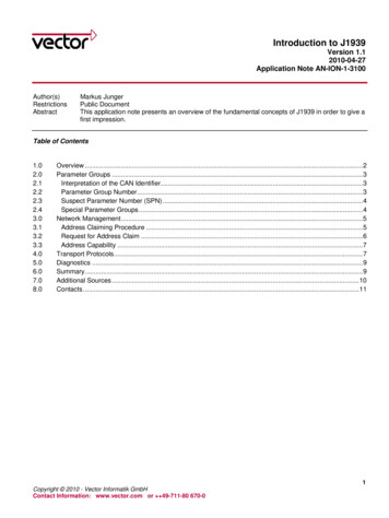
1.4.Dimensions and PinoutA mating plug kit, P/N: AX070200, is available. This kit includes the following items. NB. Thesealing plugs are only needed in cases where less than the 40 pins are required.Deutsch IPD P/N:Description:0462-201-1614148 16AWG SOCKETS SOLID 16-20AWG WIRE 6mm11401724 SEALING PLUGS SIZE 12-16 CAVITIES 12-18 AWGDRC16-40S40-PIN PLUG, No KeyDT06-08SADT SERIES PLUG 8 CONTACTW8SWEDGELOCK FOR DT 8 PIN PLUGThese items are also available from a local Deutsch IPD distributor.A crimping tool from Deutsch IPD is required to connect wiring to the sockets, P/N: HDT 48-00 orequivalent (not supplied).Typical Connections – Power and CANVersion 3.0.0Preliminary Documentation – May be Subject to Change7-27
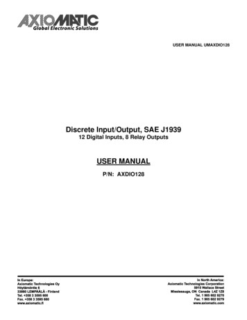
Typical Connections – Inputs and OutputsConnections – I/OINPUTDINLOADGNDLOADOUTPUTNOVersion 3.0.0NCPreliminary Documentation – May be Subject to ChangeC8-27
1.5.Installation InstructionsNOTES & WARNINGS Do not install near high-voltage or high-current devices. Ground the chassis for safety purposes and proper EMI shielding. Note the operating temperature range. All field wiring must be suitable for that temperaturerange. Install the unit with appropriate space available for servicing and for adequate wire harnessaccess (15 cm) and strain relief (30 cm). Do not connect or disconnect the unit while the circuit is live, unless the area is known to benon-hazardous.MOUNTINGThe module is designed for mounting on the engine. If it is mounted without an enclosure, the DIOshould be mounted vertically with connectors facing left and right to reduce likelihood of moistureentry.The I/O wires and CAN communication cable are considered intrinsically safe. The power wiresare not considered intrinsically safe.Mask all labels if the unit is to be repainted, so label information remains visible.Mounting ledges include holes sized for M6 or ¼ inch bolts. The bolt length will be determined bythe end-user’s mounting plate thickness. Typically 20 mm (3/4 inch) is adequate.If the module is mounted off-engine, no wire or cable in the harness should exceed 30 meters inlength. The power input wiring should be limited to 10 meters.CONNECTIONSUse the following Deutsch IPD mating plugs to connect to the integral receptacles. Wiring to thesemating plugs must be in accordance with all applicable local codes. Suitable field wiring for therated voltage and current must be used. The rating of the connecting cables must be at least85 C. Use field wiring suitable for both minimum and maximum ambient temperature.ReceptacleMating Socket (Refer to www.laddinc.com for moreinformation on the wedgelock and contacts for this matingplug.)Power and CAN bus: DT13- DT06-08SA with wedgelock W8S08PAI/O Interface Receptacle:DRC16-40SBDRC13-40PBDRC18-40SBwith sockets 0462-201-16141Axiomatic offers a mating connector plug kit, P/N AX070200, that includes the 8 pin and 40 pin(unkeyed) plugs and sockets.Version 3.0.0Preliminary Documentation – May be Subject to Change9-27
NOISE – ELECTRICAL CONNECTIONSTo reduce noise, separate all I/O wires from power wires. Shielded I/O wires will protect againstignition and injector noise.GROUNDINGProtective Earth (PE) must be connected to the module’s grounding lug to reduce the risk ofelectric shock. The conductor providing the connection must have a ring lug and wire larger than orequal to 4 mm2 (12 AWG). The ring lug should be placed between the nut and a star washer.All chassis grounding should go to a single ground point designated for the engine and all relatedequipment.The ground strap that provides a low impedance path for EMI should be a ½ inch wide, flat, hollowbraid, no more than 12 inches long with a suitable sized ring lug for the module’s grounding lug. Itmay be used in place of the PE grounding conductor and would then perform both PE and EMIgrounding functions.SHIELDINGThe I/O and CAN wiring should be shielded using a twisted conductor pair. All I/O wire shieldsshould be terminated on the shield wire available on the 40-pin connector. The I/O wires shouldnot be exposed for more than 50 mm (2 inches) without shielding. The shield may be cut off at theDIO end as it does not require termination at that end.Shields can be AC grounded at one end and hard grounded at the opposite end to improveshielding effectiveness.If the module is installed in a cabinet, shielded wiring can be terminated at the cabinet (earthground), at the entry to the cabinet or at the DIO.INPUT POWERThe main input to the power supply must be of low-impedance type for proper operation. Ifbatteries are used, an alternator or other battery-charging device is necessary to maintain a stablesupply voltage.Central suppression of any surge events should be provided at the system level.The installation of the equipment must include overcurrent protection between the power sourceand the DIO by means of a series connection of properly rated fuses or circuit breakers. Inputpower switches must be arranged external to the DIO.The power input wiring should be limited to 10 meters.Note the operating temperature range. All field wiring must be suitable for that temperature range.Version 3.0.0Preliminary Documentation – May be Subject to Change10-27
INPUT WIRINGWiring for the inputs must be shielded cable, 16 or 18 AWG. Cable lengths should be less than 30meters. Shielding should be unbroken.CAN WIRINGThe CAN port is electrically isolated from all other circuits. The isolation is SELV rated with respectto product safety requirements. Refer to the CAN specification for more information.Use CAN compatible cabling. J1939 cable is recommended as it is rated for on-engine use.Shielded CAN cable is required. The DIO provides the CAN port shield connection ac coupled tochassis ground. The chassis ground stud located on the mounting foot must be tied directly toEarth Ground.FUSINGWhen installing the unit, an external 3A, 32Vdc fuse is required.NETWORK CONSTRUCTIONAxiomatic recommends that multi-drop networks be constructed using a “daisy chain” or“backbone” configuration with short drop lines.TERMINATIONIt is necessary to terminate the network. An external CAN termination is required. No more than 2network terminations are recommended on any one network. Termination is a 121 Ohm, 0.25 W,1% metal film resistor placed between CAN H and CAN L terminals at the end two units on thenetwork.Version 3.0.0Preliminary Documentation – May be Subject to Change11-27
2. NETWORK OPERATIONThe DIO is designed to work either as a stand-alone module, or on J1939 CAN network. Whenconnected to the network, it automatically recognizes network connection, claims a networkaddress and can be configured to perform the following application tasks: Continuously broadcasts the current state of digital inputs using a proprietary InputPGN. Receives and processes OutputPGNs to control DIO output relays.The network part of DIO is compliant with Bosch CAN protocol specification, Rev.2.0, Part A andB, and the following J1939 standards:ISO/OSI Network J1939 StandardModel LayerPhysical J1939/11 – Physical Layer, 250K bit/s, Twisted Shielded Pair. J1939/15 - Reduced Physical Layer, 250K bits/sec, Un-Shielded TwistedPair (UTP).Data LinkJ1939/21 – Data Link Layer.DIO supports Transport Protocol for Commanded Address messages (PGN65240). It also supports responses on PGN Requests (PGN 59904).NetworkTransportJ1939, Appendix B – Address and Identity Assignments.J1939/81 – Network Management.DIO is an Arbitrary Address Capable ECU. It can dynamically change itsnetwork address in real time.DIO supports: Address Claimed Messages (PGN 60928), Requests forAddress Claimed Messages (PGN 59904) and Commanded AddressMessages (PGN 65240).N/A in J1939.SessionN/A in J1939.PresentationApplicationN/A in J1939.J1939/71 – Vehicle Application Layer.It transmits Software ID PGN65242 (-SOFT) only on request.DIO can constantly transmits the state of digital inputs in a user defined PDU2PGN, set to proprietary B PGN 65440 by default.DIO can receive user defined PDU2 PGN controlling output relays, set to65448 by default.DIO can receive mode select commands or send mode status feedback in auser defined PDU2 PGN, set to proprietary B PGN 65456 by default.J1939/73 – Application Layer – Diagnostics.DIO uses Memory Access Protocol (MAP) for setpoint programming from theAxiomatic Electronic Assistant Version 3.0.0Preliminary Documentation – May be Subject to Change12-27
2.1.J1939 NAMEThe DIO uses a unique J1939 Name and a dynamically configurable network ECU Address toidentify itself on the network. The DIO J1939 Name is a 64-bit parameter broadcast by the modulein Address Claimed Messages (PGN 60928) during the address claim procedure or upon request.Data fields of the name are presented in the following table:Name FieldArbitrary AddressCapableIndustry GroupVehicle SystemInstanceVehicle SystemReservedFunctionFunction InstanceECU InstanceManufacturer CodeIdentity Number21 bit2.2.Length1 bitValue1 (Capable)Setpoint TypeRead-Only3 bit4 bit0 (Global)0 (First Instance)Read-OnlyRead-Only7 bit1 bit8 bit5 bit3 bit11 bit0 (Nonspecific System)066 (I/O Controller)4 (Fifth Instance)0 (First Instance)162 (AxiomaticTechnologies Corp.)Calculated on the base ofECU Serial NumberRead-OnlyRead-OnlyRead-OnlyRead-OnlyUser programmable through MAPRead-OnlyShould be programmed only by themanufacturer and reflect a serialnumber printed on DIO label.Network AddressDuring the first connection to a J1939 network, the DIO claims a user configurable ECU Address(default value 128 – Start of dynamic address assignment range for self-configurable ECUs). If theaddress is taken, the module tries to use another available network address until it finds a freeone. This address will be stored in nonvolatile memory as a new ECU Address and will be claimednext time the module is connected to the network.DIO network address can also be changed using Commanded Address Messages (PGN 65240)sent by any ECU on the network or using J1939 Memory Access Protocol.2.3.Software IdentifierAfter the DIO establishes communication on the network, other ECUs can retrieve DIO softwareidentifier through PGN65242 (-SOFT). For simplicity, DIO identification is sent in a single-framemessage. The message has the following format:Transmission Repetition Rate:Data Length:Data Page:PDU Format:PDU Specific:Default Priority:Parameter Group Number:Version 3.0.0On request8 bytes0254218665242 (0x00FEDA16)Preliminary Documentation – May be Subject to Change13-27
Bit Start Length ValuePosition/ Bytes11 byte 0x012-43bytes51 byte61 byte71 byte81 byteSPN DescriptionRequired by the standard.Number of Software Id Fields.Only one in this case since TP protocol is notsupportedModuleIDProprietary formatted field.Three-character module ID with firstcharacter at byte 2. Spaces should be put inplace of unused positions.DIO module ID is ‘DIO’.HardwareRevisionCode Proprietary formatted field.ASCII symbol for BCD presentation ofHardware Revision Code.SoftVersionMajorCode Proprietary formatted field.ASCII symbols for BCD presentation ofSoftware Version Major Code.SoftVersionMinorCode Proprietary formatted field.ASCII symbol for BCD presentation ofSoftware Version Minor Code.*Required by the standard.Software ID field delimiter.SPN965234For example, DIO with hardware version 2 and software version V1.5 will reply on the PGN65242request the following way:PositionCharacterByte2.4.12345678DIO215*0x01 0x44 0x49 0x4F 0x32 0x31 0x35 0x2ADigital Input State MessageThe DIO can be setup to transmit the state of the digital inputs through a proprietary InputPGN.Transmission Repetition Rate:Data Length:Data Page:PDU Format:PDU Specific:Default Priority:Parameter Group Number:Configurable, Default 250ms8 bytes0PDU2 format (240-255). 255 by default. Depends on PGNDepends on PGN6Configurable “InputPGN”, Default 65440 [0xFFA0]The InputPGN is always available on request. If the transmission repetition rate is set to zero, it isonly available on request.Version 3.0.0Preliminary Documentation – May be Subject to Change14-27
The content of the message depends on a configurable parameter that tells the DIO how is data isto be sent. There are two methods of sending data on the Digital Input State message, either in a“Compact” or “Expanded” format.COMPACT DATACompact data is sent using a proprietary format similar to PGN65241 (-AUXIO). Here, 4 separateinput channels are sent on the same Byte in the message, as per the table below.Bit Start Position LengthSPN DescriptionSPN/ Bytes1.12 bitsInput #04Not assigned1.32 bitsInput #03Not assigned1.52 bitsInput #02Not assigned1.72 bitsInput #01Not assigned2.12 bitsInput #08Not assigned2.32 bitsInput #07Not assigned2.52 bitsInput #06Not assigned2.72 bitsInput #05Not assigned3.12 bitsInput #12Not assigned3.32 bitsInput #11Not assigned3.52 bitsInput #10Not assigned3.72 bitsInput #09Not assigned4-85 bytesReserved (always set to 0xFF)Not assignedEXPANDED DATAExpanded data is sent using 1 Byte/Input. Since there are twelve inputs on the DIO, the upper 4channels are actually sent on a different PGN, which is the “Input PGN” 1. The data is sent asper the table putPGNInputPGNInputPGNInputPGN 1InputPGN 1InputPGN 1InputPGN 1InputPGN 1Version 3.0.0Byte Index0123456701234 to 7SPN DescriptionInput #1Input #2Input #3Input #4Input #5Input #6Input #7Input #8Input #9Input #10Input #11Input #12Reserved (always set to 0xFF)SPNNot assignedNot assignedNot assignedNot assignedNot assignedNot assignedNot assignedNot assignedNot assignedNot assignedNot assignedNot assignedNot assignedPreliminary Documentation – May be Subject to Change15-27
In either data conversion method, each Input SPN can be in one of the following states:NameValueInput OFF0Input ONError IndicatorNot available12 – Not used3 – Not usedIf digital inputs do not change their states, the InputPGN is sent continuously at the configuredtransmission rate. If state of any digital input changes from 0 to 1 or from 1 to 0, a new messagereflecting this change is sent immediately without the transmission delay. However, a debouncingcontrol will not allow a digital input to change its state faster than once in 30-40 ms, see thefollowing example:Channel #1state hasbeen changedNo changeChannel #5state hasbeen changedNo changeNo changeTime1234 5250 msUndefined,but less than250msVersion 3.0.030-40 ms6Message Number250 msChannel #1 state hasbeen changed again.Preliminary Documentation – May be Subject to Change16-27
2.5.Relay Control MessageThe DIO can be setup to response to a control message received from the J1939 bus that wassent on a proprietary OutputPGN.Transmission Repetition Rate:Data Length:Data Page:PDU Format:PDU Specific:Default Priority:Parameter Group Number:Configurable, Default 250ms(Expected transmission rate from external ECUs)8 bytes0PDU2 format (240-255). 255 by default. Depends on PGNDepends on PGN6Configurable “OutputPGN”, Default 65448 [0xFFA8]The “OutputPGN” is available on request, and when requested, the DIO will send the states ofeach relay at the time the request was received.How the DIO interprets the content of the message depends on a configurable parameter that tellsthe DIO how is data is to be received. There are two methods of receiving data on the RelayControl Message, either in a “Compact” or “Expanded” format.COMPACT DATACompact data is received using a proprietary format similar to PGN65241 (-AUXIO). Here, 4separate output channels are controlled on the same Byte in the message, as per the table below.Bit Start Position/ Bytes1.11.31.51.72.12.32.52.73-8Version 3.0.0LengthSPN DescriptionSPN2 bits2 bits2 bits2 bits2 bits2 bits2 bits2 bits6 bytesOutput #04 Commanded StateOutput #03 Commanded StateOutput #02 Commanded StateOutput #01 Commanded StateOutput #08 Commanded StateOutput #07 Commanded StateOutput #06 Commanded StateOutput #05 Commanded StateReserved (not processed)Not assignedNot assignedNot assignedNot assignedNot assignedNot assignedNot assignedNot assignedNot assignedPreliminary Documentation – May be Subject to Change17-27
When the DIO receives a request for the OutputPGN, in Compact data mode it will respond withthe state of 4 separate output channels on the same Byte in the message, as per the table below.Bit Start Position/ Bytes1-67.17.37.57.78.18.38.58.7LengthSPN DescriptionSPN6 bytes2 bits2 bits2 bits2 bits2 bits2 bits2 bits2 bitsReserved (always set to 0xFF)Output #04 Actual StateOutput #03 Actual StateOutput #02 Actual StateOutput #01 Actual StateOutput #08 Actual StateOutput #07 Actual StateOutput #06 Actual StateOutput #05 Actual StateNot assignedNot assignedNot assignedNot assignedNot assignedNot assignedNot assignedNot assignedNot assignedEXPANDED DATAExpanded data is received using 1 Byte/Output. The data is interpreted as per the table PGNOutputPGNOutputPGNOutputPGNByte Index01234567SPN DescriptionOutput #01 Commanded StateOutput #02 Commanded StateOutput #03 Commanded StateOutput #04 Commanded StateOutput #05 Commanded StateOutput #06 Commanded StateOutput #07 Commanded StateOutput #08 Commanded StateSPNNot assignedNot assignedNot assignedNot assignedNot assignedNot assignedNot assignedNot assignedWhen the DIO receives a request for the OutputPGN, in Expanded data mode it will respond withthe state of each output channels on its own Byte in the message, as per the table tPGNOutputPGNOutputPGNOutputPGNVersion 3.0.0Byte Index01234567SPN DescriptionOutput #01 Actual StateOutput #02 Actual StateOutput #03 Actual StateOutput #04 Actual StateOutput #05 Actual StateOutput #06 Actual StateOutput #07 Actual StateOutput #08 Actual StateSPNNot assignedNot assignedNot assignedNot assignedNot assignedNot assignedNot assignedNot assignedPreliminary Documentation – May be Subject to Change18-27
In either data conversion method, each Output SPN can be in one of the following states:NameValueRelay OFF0Relay ON1Error Indicator2 – Not ProcessedNot available3If the DIO is configured to expect the OutputPGN message at a particular update rate, themessage must be present on the bus in that timeframe in order to keep the controlled relaysenergized. It is assumed, that two different ECUs will not try to control the same relayindependently; it is against J1939 standard and DIO has no support to handle this situation.Normally, once energized by Relay ON command in OutputPGN message, a relay should be deenergized by Relay OFF command. The expected value of the delay between a command, sentthrough the network, and the action on the command is around 20ms and depends on: relayswitching, network transmission and message processing delays.In case a relay was energized, but DIO has not received any Relay ON or Relay OFF messagesfor approximately three time the expect receive rate, it will automatically go into the configured“CAN Fault” mode. (See Section 3 for more information) To avoid situation when a controlmessage is lost due to very heavy network traffic, the DIO will request twice the OutputPGN fromthe node controlling the relay before going into the fault mode.The times at which the DIO will send the requests for the OutputPGN are determined by thefollow
Discrete Input/Output, SAE J1939 12 Digital Inputs, 8 Relay Outputs USER MANUAL P/N: AXDIO128 . . J1939/71 Vehicle Application Layer, SAE, December 2004 J1939/73 Application Layer-Diagnostics, SAE, March 2004 J1939/81 Network Management, SAE, May 2003