Transcription
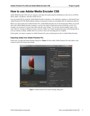
Touch EncoderInterface Control Document(CANBUS J1939 Protocol)TE OS Version 1.0.0 or greater (includes UtilityApp)Questions? Please contact TE@Grayhill.comBulletin 1295 Rev 04/19
Revision HistoryRevisionDateDescriptionA2/19/2018Original ReleaseB2/27/2018Changes to the example message in section 2.5.2Rephrased the meaning of Byte 7 in section 2.5.2C3/6/2018Changed Byte message in section 3.1D07/25/2018Changed pinout on M12 to reflect production pinoutE8/24/2018Added Programming Harness InformationF10/25/2018Updated Run/Programming Mode SchematicsG12/7/2018Updated Touch Encoder ImageH2/12/2019Added Command, Multi-value, and Display CodeInformationQuestions? Please contact TE@Grayhill.comBulletin 1295 Rev 04/19
Table of Contents1.2.3.4.Overview . 41.1Reference Documents . 41.2Programmable Features (Coming Soon) . 4J1939 Communications. 52.1Message Header Description . 52.2J1939 Bitfield Location and Byte Ordering . 62.3Grayhill Touch Encoder Source Address . 62.4Physical Layer . 62.5Standard Messages . 7Configuration and Control Commands. 103.1Modify Widget Data3.2Modify Events Data PGN3.3Modify Events Data Priority3.4Modify Events Data Transmission Period 211 (0xD3) . 133.5Modify Widgets Data PGN3.6Modify Widgets Data Priority3.7Modify Widgets Data Transmission Period 219 (0xDB) . 143.8Modify Source Address3.9Backlight Intensity . 143.10Changing J1939 NAME Fields (COMING SOON) 228 (0xE4) . 153.11Change ECUID Command (COMING SOON) 229 (0xE5) . 153.12Change ECUID Field Data (COMING SOON) 230209 (0xD1) . 12210 (0xD2) . 12217 (0xD9) . 13218 (0xDA) . 13224 (0xE0) . 14(0xE6) . 16Other J1939 Commands . 164.1.1Address Claimed (COMING SOON) . 164.1.2PGN Request (COMING SOON) . 174.1.2.1ECU Identification Information (COMING SOON) . 174.1.2.2Software Identification (COMING SOON) . 184.1.35.17 (0x11) . 10Acknowledgement Message (COMING SOON) . 19Appendix . 205.1Programming Harness . 20Questions? Please contact TE@Grayhill.comBulletin 1295 Rev 04/19
1. OverviewThis document describes the functionality and communication of the Grayhill Touch Encoder product.1.1 Reference DocumentsThe following documents are referenced within this document.1. SAE-J19392. SAE-J1939/113. SAE-J1939/214. SAE-J1939/715. SAE-J1939/811.2 Programmable Features (Coming Soon)The following fields can be configured by Grayhill prior to leaving the factory. Requests for customconfiguration will be captured in the top-level CAD drawingDefaultValueComments64ERASEDPer SAE-J1939/7164ERASEDPer SAE-J1939/72Field NameParameter TypeSize (bytes)ECUID PNASCII CHARSECUID LOCASCII CHARSRangeECUID TYPEASCII CHARS64ERASEDPer SAE-J1939/73J1939 NAME ECU INSTANCEJ1939 NAME FUNCTION INSTANCEINTEGERINTEGER3 bits5 bits0-70 - 3100J1939 NAME FUNCTIONINTEGER8 bits0 - 255135J1939 VEHICLE SYSTEMINTEGER7 bits0 - 1270J1939 VEHICLE SYSTEM INSTANCEINTEGER4 bits0 - 150J1939 NAME INDUSTRY GROUPINTEGER3 bits0-70J1939 NAME ARBITRARY ADDRESS CAPABLESection 3.6Section 3.6Per SAE-J1939Base Spec Appx BPer SAE-J1939Base Spec Appx BSection 3.6Per SAE-J1939Base Spec Appx BINTEGER1 bit0-10Per SAE-J1939/81J1939 SOURCE ADDRESSBYTE10 - 254242 (F2H)EVENT DATA PGN20-6553865295(FF0FH)Per SAE-J1939Base SpecEVENT DATA PRI20-76Section 3.3EVENT DATA SOE (Send On Event)10-11Section 3.4EVENT DATA TX PER10-254Section 3.4WIDGETS DATA PGN20-65538WIDGETS DATA PRI20-7065297(FF11H)6WIDGETS DATA SOE (Send On Event)10-11Section 3.7WIDGETS DATA TX PER10-2540Section 3.7Questions? Please contact TE@Grayhill.comSection 3.2Section 3.5Section 3.6Bulletin 1295 Rev 04/19
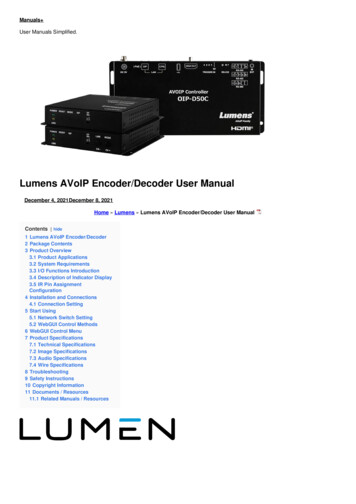
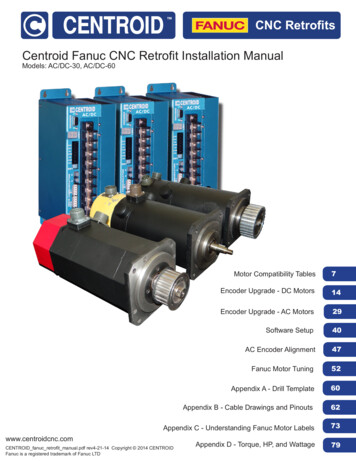
2. J1939 Communications2.1 Message Header DescriptionData PagePriorityReservedFigure 1 illustrates the format of the CAN message ID. A brief description of each field follows.PDU Format (PF)PDU Specific (PS)Source AddressFigure 12.1.1 PriorityThis 3-bit field is used to define the priority during arbitration. ‘000’ is the highest priority and is usuallyassociated with high-speed control messages. Low priority is used for non-critical configuration andinformation messages.2.1.2 DP (Data Page)This 1-bit field defines on which data page (0 or 1) the message is defined in the J1939 specification.Page 0 contains the messages that are presently defined, while Page 1 is for future expansion accordingto J1939.2.1.3 Protocol Data Unit (PDU) - PDU Format (PF)This 8-bit field determines the format of the message and is one of the fields which determine theParameter Group Number of the message (see 2.1.6). If the value is between 0 and 239, the message isa PDU 1 Format message. These messages are sent to specific addresses.2.1.4 Protocol Data Unit (PDU) - PDU Specific (PS)The PDU Specific (PS) field is the Destination Address (DA). If the value is between 240 and 255, themessage is a PDU 2 Format message. These messages are not sent to a specific address, but areinstead broadcasted to the entire network. The PS then becomes the Group Extension (GE) field.2.1.5 Source AddressThis 8-bit field is the source address of the device that sent the message.2.1.6 Parameter Group NumberJ1939 defines allowable messages by their Parameter Group Number (PGN). The Parameter GroupNumber is a 3-byte value that uniquely defines the message purpose. A PGN has the following format: Ifthe PDU Format value for a message is less than 240, then the last 8 bits of the PGN are set to ‘0’. Thespecification gives the decimal equivalent of the PGNs. To obtain the PF and PS values to use for aspecific message, convert the decimal value from the specification to hexadecimal and use the last twobytes. These values can then be used to either send messages on the network or to request messagesfrom other source addresses.Questions? Please contact TE@Grayhill.comBulletin 1295 Rev 04/19
2.2 J1939 Bitfield Location and Byte OrderingThe byte and bit ordering and location within the data field are per the J1939 specification. The first databyte is sent first and is referenced as Byte 1. The LSB of the data bytes are on the right and arereferenced as Bit 1.The convention used to locate a parameter in the data field is the same as specified in SAE-J1939/71.The format used is “R.x” where R is the byte number and x is the starting bit number within the byte. Thelength is the number of bits starting at this point.Example 1: Location 4.3 with a length of 3 bits would have the value of 1 as illustrated below.Byte 4 0x67 0b01100111. The bold value is the three bit field holding a value of 0b001.Example 2: Location 4.3 with a length of 3 bits would have the value of 6 as illustrated below.Byte 4 0x7b 0b01111011. The bold value is the three bit field holding a value of 0b110.2.3 Grayhill Touch Encoder Source AddressThe source address of the Grayhill Touch Encoder device is set to 242 (0xF2) at the factory. This may bemodified dynamically if Dynamic Addressing is turned on, with the Commanded Address message inaccordance with J1939-81, or with the proprietary Source Address Command. The source address valueis stored in non-volatile memory. The ability to change the source address will allow multiple TouchEncoder devices to coexist in the same system.2.4 Physical LayerThe bit rate is 250kbps per J1939/11.For Touch Encoder serial numbers less than A100000 please contact Grayhill for pinout detail.If MODE Pin is floating at power up, the Touch Encoder will assume run mode operation. If Mode pin isconnected to GND externally at startup, the Touch Encoder will assume programming mode. The TouchEncoder will download updates from a USB mass storage device (if connected) and update the TouchEncoder accordingly.Questions? Please contact TE@Grayhill.comBulletin 1295 Rev 04/19
Run Mode:See previous page:Connector PinoutsProgramming Mode:See previous page:Connector PinoutsRecommended Flash Drives:Verbatim 49304SanDisk SDCZ60-016G-B35Note: Load files to FLASH drive and plug into socket. Touch Encoder only samples the MODE pin duringpower up, so be sure this occurs after connecting the harness and FLASH drive.2.5 Standard MessagesThe Events Data message and the Widget Data message all use the Proprietary B PDU2 format (PF 255) that broadcasts to no specific address the status of the device. The Control Data message usesProprietary A PDU1 format (PF 239).2.5.1 Events Data MessagePriority – 0b110 (6)R/DP – 0b00(0)PF – 0xFF(255), Proprietary B PDU2 FormatGrpExt – 0x0F (15)SrcAddr – 0xF2 (242), i.e. Touch Encoder default source addressID – 0x18FF0FF2Direction - TransmitData Length – 8 bytesTransmission Rate – On Event (programmable)*The Events Data PGN can be reassigned using a configuration command.Questions? Please contact TE@Grayhill.comBulletin 1295 Rev 04/19
Start1.1Length8 bitsDesc.ScreenNumber2.13.18 bits8 bitsReservedEvent ID4.18 bitsEncoder(relative)Values0x01 – Screen #1 at the time of event 0xFF – Screen #255 at the time of eventReserved for future use0x01- Events: Standard (Relative Encoder, Taps,Swipes)0x80 – No Change0x81 – Clockwise 1 detent0x82 – Clockwise 2 detents 0xFE – Clockwise 126 detents0x7F – Counter-Clockwise 1 detent0x7E – Counter-Clockwise 2 detents 0x01 – Counter-Clockwise 127 detents5.116 bitsTap Mask7.18 bitsSwipe Mask0x00 – Not used0xFF – Not used0x0000 – No Tap detected0x0001 – Tap in Zone 1 detected0x0002 – Tap in Zone 2 detected0x0004 – Tap in Zone 3 detected 0x4000 – Tap in Zone 15 detected0x8000 – Tap on screen (anywhere) detected0x00 – No Swipe detected0x01 – Swipe Up detected0x02 – Swipe Down detected0x03 – Swipe Left detected0x04 – Swipe Right detected0x80 – Swipe (any direction) detectedThe Events Data message is sent to inform the receiving (host) ECU of any new encoder, tap or swipeevents that occurred on the Touch Encoder device. If such an event causes a new screen to bedisplayed or if any of the Value IDs on the current screen were changed, the event is followed by aWidget Data message or messages which, on a screen change, will communicate the data in all ValueIDs on the new screen.Example: Turning the encoder counter-clockwise by 2 detents on screen 1 (since last message) will resultin the following message being transmitted.ID 0x18FF0FF2, LEN 8, DATA 0x01,0x00,0x01,0x7E,0x00,0x00,0x00,0xFFExample: Swiping up on the touch pad on screen 5 will result in the following message being transmitted.ID 0x18FF0FF2, LEN 8, DATA 0x05,0x00,0x01,0x80,0x00,0x00,0x81,0xFFExample: Tapping in screen 10 zone 4 of the touch pad will result in the following message beingtransmitted.ID 0x18FF0FF2, LEN 8, DATA 0x0A,0x00,0x01,0x80,0x80,0x08,0x00,0xFF2.5.2 Widget Data MessageQuestions? Please contact TE@Grayhill.comBulletin 1295 Rev 04/19
Priority – 0b110 (6)R/DP – 0b00(0)PF – 0xFF(255), Proprietary B PDU2 FormatGrpExt – 0x11 (17)SrcAddr – 0xF2 (242), i.e. Touch Encoder default source addressID – 0x18FF11F2Direction - TransmitData Length – 8 bytesTransmission Rate – On Event (programmable)*The Widget Data PGN can be reassigned using a configuration command.As described in the previous section, if an event on the Touch Encoder Device causes a new screen tobe displayed or if the event causes a change in one of the active Value IDs on the current screen, theEvents Data message is immediately followed by a Widget Data message.Due to CAN restrictions on the number of data bytes allowed per CAN report, Widget Data messageswith multiple Value IDs need to split up into several reports. The number of reports needed is thatnumber of Value IDs.Example 1: For a single active Value ID, only one CAN report is needed.StartLengthDesc.1.18 bitsScreenNumber2.18 bitsReserved3.18 bitsValue ID4.116 bitsCurrentValue6.18 bitsDisplayCode7.1Values0x01 – Screen #1 currently being displayed 0xFF – Screen #255 currently being displayedReserved for future use0x00 – No Values on this screen0x01 – Value ID #10x02 – Value ID #20x04 – Value ID #3 0x80 – Value ID #8Value currently being displayed for the givenValue ID. This value is of the format specified byits Display Code valueDisplay Code for this Value0x00 – Not used0x01 – Value ID (Value #1 is active for this screen)Active0x02 – Value ID (Value #2 is active for this screen)8 bitsValue ID Bitmask0xFF – Value ID (All 8 Values active for thisscreen)Figure 2 – Single Report needed for a single active Value IDFor multiple active Value IDs, multiple Widget Data messages are sent consecutively. As this scenariorequires multiple CAN reports, the Value ID indicates the current report.Example 2: For 2 active Value IDs, two separate reports are needed to convey all of the Widgetinformation. Below is an example of the report messages with a widget that has two ValueIDs . The firstbeing a temperature setting of 75 and the second being a fan speed of 5.Questions? Please contact TE@Grayhill.comBulletin 1295 Rev 04/19
ID 0x18FF11F2, LEN 8, DATA 0x01,0x00,0x01,0x4B,0x00,0x00,0x03,0xFFID 0x18FF11F2, LEN 8, DATA 0x01,0x00,0x02,0x05,0x00,0x00,0x03,0xFF2.5.3 Configuration and Control MessagePriority – 0b110 (6)R/DP – 0b00(0)PF – 0xEF(239) Proprietary A PDU1 FormatPS – DestAddr, i.e. address of the Touch Encoder device, default value: 242 (0xF2)SrcAddr – 0x21 (33), i.e. example source addressID – 0x18EFF221Direction - ReceiveData Length – 8StartLength1.11 Byte2.17 BytesDesc.Configuration andControl CommandConfiguration andControl DataValuesCommand Byte as described in Sec. 3Variable as described in Sec. 33. Configuration and ControlCommandsChanging of the configuration and how the Touch Encoder device behaves is done with the Configurationand Control message described in Sec 2.5.3. The first byte serves as the command byte. Where applicable,changes take effect immediately and are stored in non-volatile memory unless otherwise noted.Note that some commands will only take effect if sent from a source address of 249 (0xF9). For all othercommands, the following examples will assume a source address of 33 (0x21).The header information for these commands is as follows:Priority – 0b110 (6)R/DP – 0b00(0)PF – 0xEF(239)PS – DestAddr, i.e. address of the Touch Encoder device, default value: 0xF2 (242)SrcAddr – 0x21 (33), i.e. example source addressID – 0x18EFF221, Proprietary A PDU1 FormatDirection - Receive3.1 Modify Widget DataData Length – 7 bytesQuestions? Please contact TE@Grayhill.com17 (0x11)Bulletin 1295 Rev 04/19
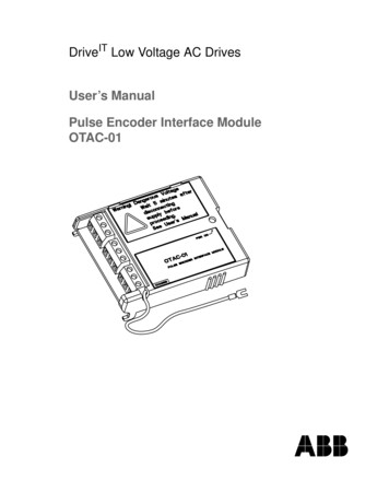
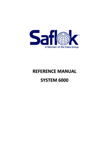
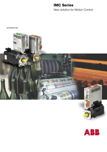
Start1.1Length8 bitsDesc.CommandValues0x11 – Force Widget Data2.18 bitsScreenNumber3.18 bitsValue ID4.116 bitsCurrent Value6.17.18 bits8 bitsDisplay CodeActive ValueID Bitmask0x00 – Screen #0 to be displayed0x01 – Screen #1 to be displayed 0xFF – Screen #255 to be displayed0x00 – No altered Values0x01 – Value ID #10x02 – Value ID #20x04 – Value ID #3 0x80 – ValueID #8Value to be displayed. This value is of the format specified byDisplay Code valueDisplay Code for this Value0x00 – Not used0x01 – Value #1 currently active0x02 – Value #2 currently active 0x80 – All 8 Values currently activeExample: Sending the following message to a Touch Encoder device having the default address of 0xF2 willset the current screen to be displayed to 0x03 and the current value of ValueID #2 of that screen to 0x01F4.ID 18EFF221, LEN 8, Data 0x11, 0x03, 0x02, 0xF4, 0x01, 0x00,0x02, 0xFF3.1.1 Multi-Value Data ExampleDynamic Text ObjectValue ID #2Lighted Icon ObjectValue ID #3Example: The figure above displays an example of a multi-value widget. The dynamic text object is designatedat Value ID #2. The lighted icon object is designated as Value ID #3. Below is the sequence of messages to turnQuestions? Please contact TE@Grayhill.comBulletin 1295 Rev 04/19
on the top lighted icon and change the dynamic text to 100. Note that the lighted icon object has an offset of0x8000ID 18EFF221, LEN 8, Data 0x11, 0x03, 0x04, 0x01, 0x80, 0x00, 0x06, 0xFFID 18EFF221, LEN 8, Data 0x11, 0x03, 0x02, 0x64, 0x00, 0x00, 0x06, 0xFF3.1.2 Display CodeDisplay Code gives the Touch Encoder the ability to display decimal numbers. The Display Code is one byte inlength, with the upper four bits being the decimal code and the lower 4 bits reserved for future use. The decimalcode is a signed four bit integer. The table below describes how the decimal code worksDisplay Code Byte0x0X0x1X0x2X0xEX0xFXDefault integer numberInteger x 10 e.g. 10 100Integer x 100 e.g. 10 1000Integer 100 e.g. 10 0.10Integer 10 e.g. 10 1.03.2 Modify Events Data PGN209 (0xD1)Data Length – 8 bytesByte 1Byte 2Byte 3Byte 4Byte 5Byte 6Byte 7Byte 80xD1aabbxxxxxx0x550xAAaa – The least significant byte of the new PGN. Valid Range: 0.255bb - The most significant byte of the new PGN. Valid Range: 0.255xx – Don’t Care. Should be 0xFF following J1939 convention0x55 – Low byte of 16 bit key0xAA – High byte of 16 bit key3.3 Modify Events Data Priority210 (0xD2)Data Length – 8 bytesQuestions? Please contact TE@Grayhill.comBulletin 1295 Rev 04/19
Byte 1Byte 2Byte 3Byte 4Byte 5Byte 6Byte 7Byte 80xD2ddxxxxxxxx0x550xAAdd – The new priority. Valid Range: 0.7xx – Don’t Care. Should be 0xFF following J1939 convention0x55 – Low byte of 16 bit key0xAA – High byte of 16 bit key3.4 Modify Events Data Transmission Period211 (0xD3)Data Length – 8 bytesByte 1Byte 2Byte 3Byte 4Byte 5Byte 6Byte 7Byte 80xD3ddEventxxxxxx0x550xAAdd – The value multiplied by 10ms. Valid range: 1.255 yielding between 10ms to 2.54 seconds. A valueof zero automatically assumes transmit upon event.Event – Valid settings is 0 or 1. A value of one sends the key message upon change in key information.Upon transmission the timer is reset. A value of zero will cause the message to be transmitted onlyat the specified time interval.xx – Don’t Care. Should be 0xFF following J1939 convention0x55 – Low byte of 16 bit key0xAA – High byte of 16 bit key3.5 Modify Widgets Data PGN217 (0xD9)Data Length – 8 bytesByte 1Byte 2Byte 3Byte 4Byte 5Byte 6Byte 7Byte 80xD9aabbxxxxxx0x550xAAaa – The least significant byte of the new PGN. Valid Range: 0.255bb - The most significant byte of the new PGN. Valid Range: 0.255xx – Don’t Care. Should be 0xFF following J1939 convention0x55 – Low byte of 16 bit key0xAA – High byte of 16 bit key3.6 Modify Widgets Data Priority218 (0xDA)Data Length – 8 bytesQuestions? Please contact TE@Grayhill.comBulletin 1295 Rev 04/19
Byte 1Byte 2Byte 3Byte 4Byte 5Byte 6Byte 7Byte 80xDAddxxxxxxxx0x550xAAdd – The new priority. Valid Range: 0.7xx – Don’t Care. Should be 0xFF following J1939 convention0x55 – Low byte of 16 bit key0xAA – High byte of 16 bit key3.7 Modify Widgets Data Transmission Period 219 (0xDB)Data Length – 8 bytesByte 1Byte 2Byte 3Byte 4Byte 5Byte 6Byte 7Byte 80xDBddEventxxxxxx0x550xAAdd – The value to be multiplied by 10ms. Valid range: 1.255 yielding between 10ms to 2.55 seconds. Avalue of zero automatically assumes transmit upon event.Event – Valid settings is 0 or 1. A value of one sends the key message upon change in key information.Upon transmission the timer is reset. A value of zero will cause the message to be transmitted onlyat the specified time interval.xx – Don’t Care. Should be 0xFF following J1939 convention0x55 – Low byte of 16 bit key0xAA – High byte of 16 bit key3.8 Modify Source Address224 (0xE0)Data Length – 8 bytesByte 1Byte 2Byte 3Byte 4Byte 5Byte 6Byte 7Byte 80xE0ddxxxxxxxx0x550xAAdd – Has a value between 128 and 245 and is the new source addressxx – Don’t Care. Should be 0xFF following J1939 convention0x55 – Low byte of 16 bit key0xAA – High byte of 16 bit key3.9 Backlight IntensityData Length – 8 bytesQuestions? Please contact TE@Grayhill.comBulletin 1295 Rev 04/19
Byte 1Byte 2Byte 3Byte 4Byte 5Byte 6Byte 7Byte 80x80xxddxxxxxxxxxxdd – Has a value between 0 and 100 and is the percentage of backlight intensityxx – Don’t Care. Should be 0xFF following J1939 convention3.10 Changing J1939 NAME Fields (COMING SOON) 228 (0xE4)*Note: Must be sent from source address of 249 (0xF9)Data Length – 8 bytesByte 1Byte 2Byte 3Byte 4Byte 5Byte 6Byte 7Byte 80xEAsubcmddb0db1db2xx0x550xAAsubcmd – Represents the field within the name to change.db0, db1, db2 – Data bytes associated with the sub command, LSB to MSB respectively.xx – Don’t Care. Should be 0xFF following J1939 convention0x55 – Low byte of 16 bit key0xAA – High byte of 16 bit keySub CommandsSub CmdFieldDescription0ID21 bits of db0.21ECU InstanceBits 3.1 of Byte 5 (Most Significant at 3)2Function InstanceBits 8.4 of Byte 5 (Most Significant at 8)3FunctionBits 8.1 of Byte 6 (Most Significant at 8)5Vehicle SystemBits 8.2 of Byte 7 (Most Significant at 8)4Vehicle System InstanceBits 4.1 of Byte 8 (Most Significant at 4)6Industry GroupBits 7.5 of Byte 8 (Most Significant at 7)7Arbitrary Addr. CapableBit 8 of Byte 8Refer to J1939 base document for field value ranges and relationships.3.11 Change ECUID Command (COMING SOON) 229 (0xE5)*Note: Must be sent from source address of 249 (0xF9)Data Length – 8 bytesQuestions? Please contact TE@Grayhill.comBulletin 1295 Rev 04/19
Byte 1Byte 2Byte 3Byte 4Byte 5Byte 6Byte 7Byte 80xEB0.2ddxxxxxx0x550xAA0 – Selects ECUID Part Number to change1 – Selects ECUID Location to change2 – Selects ECUID Type to changedd – Number of ASCII characters in the field, max of 643.12 Change ECUID Field Data (COMING SOON) 230 (0xE6)*Note: Must be sent from source address of 249 (0xF9)Data Length – 8 bytesByte 1Byte 2Byte 30xECByte 4Byte 5Byte 6Byte 7Byte 81 to 7 bytes of ASCII Data* No Key used in bytes 7 and 8.4. Other J1939 CommandsThe following messages are defined in the J1939 documents and are implemented in the Touch Encoderdevice.4.1.1 Address Claimed (COMING SOON)Priority – 0b110(6)R/DP – 0b00(0)PF – 0xEE(238), Address ClaimedPS – DestAddr, address should always be the Global Address, 0xFF?SrcAddr – 0xF2(242), i.e. Touch Encoder source addressID – 0x18EEFFF2, Proprietary A PDU1 FormatDirection – TransmitData Length – 8Transmission Rate – Upon boot or whenever requestedStartLengthDesc.1.121 BitsIdentity Number0 to 221-13.611 BitsManufacturers Code294 (Assigned to Grayhill by SAE)Questions? Please contact TE@Grayhill.comValuesBulletin 1295 Rev 04/19
5.13 BitsECU Instance0 (Default)5.45 BitsFunction Instance0 (Default)6.18 BitsFunction135 (Keypad, Default) *7.11 BitReserved0 (Defined by SAE)7.27 BitsVehicle System0 (Default) *8.14 BitsVehicle System Instance0 (Default)8.53 BitsIndustry Group8.81 BitArbitrary AddressCapable0 Global (Default) *1 On-Highway Equipment2 Agricultural and Forestry Equipment3 Construction Equipment4 Marine5 Industrial-Process ControlStationary6 & 7 Reserved0 Not Capable1 Capable (Default)*Refer to J1939 base document for the Function value based on the Industry Group and Vehicle Systemcombinations4.1.2 PGN Request (COMING SOON)Priority – 0b110 (6)R/DP – 0b00(0)PF – 0xEA(234), PGN Request, Proprietary A PDU1 FormatPS – DestAddr, address of the Touch Encoder device to respond or the Global AddressSrcAddr – 0x21 (33), i.e. example source addressID – 0x18EAF221Direction - ReceiveData Length – 3StartLengthDesc.ValuesByte 1 of PGN being requested1.11 Byte0 to 255(LSB)2.11 ByteByte 2 of PGN being requested0 to 2553.11 ByteByte 3 of PGN being requested(MSB)0The following are the supported PGN’s that can be requested from the keypad.unsupported the keypad responds with a NACK (Refer to J1939-21).If the request is4.1.2.1 ECU Identification Information (COMING SOON)Priority – 0b110R/DP – 0b00PF – 0xFD(6)(0)(253), ECU ID, Proprietary B PDU2 FormatQuestions? Please contact TE@Grayhill.comBulletin 1295 Rev 04/19
PS – 0xC5(197)?SrcAddr – 0xF2(242), i.e. Touch Encoder source addressID – 0x18FDC5F2Direction – TransmitData Length – VariableTransmission Rate – Upon RequestMulti Packet Transerred – Yes, BAM onlyStartLengthDesc.Values *A 64ECU Part NumberEx. “3KYY1001-1”B 64ECU Serial NumberEx. “123456”C 64ECU LocationEx. “CAB”D 64ECU Type“KEYPAD”*All fields asterisk delimited4.1.2.2 Software Identification (COMING SOON)Priority – 0b110(6)R/DP – 0b00(0)PF – 0xFE(254), SW ID, Proprietary B PDU2 FormatPS – 0xDA(218)SrcAddr – 0xF2(242), i.e. Touch Encoder source addressID – 0x18FEDAF2Direction – TransmitData Length – VariableTransmission Rate – Upon RequestMulti Packet Transferred – Yes, BAM onlyStart1Length1 Byte2-NVariableDesc.Number of softwarefieldsSoftware ID fieldQuestions? Please contact TE@Grayhill.com1 to 125ValuesASCII characters. Each field delimitedwith an asterisk and up to 200 charactersBulletin 1295 Rev 04/19
4.1.3 Acknowledgement Message (COMING SOON)Priority – 0b110(6)?R/DP – 0b00(0)PF – 0xE8(232), SW ID, Proprietary A PDU1 FormatPS – 0x22(34), i.e. example destination address?SrcAddr – 0xF2(242), i.e. Touch Encoder source addressID – 0x18E822F2Direction - TransmitData Length – 8Priority - 6Transmission Rate – Upon appropriate responseStartLengthDesc.11 ByteControl Byte21 ByteGroup Function3-53 BytesReserved by SAE6-83 BytesParameter Group beingAcknowledgedValues *0 Positive Acknowledgement1 Negative Acknowledgement2 Access Denied3 Cannot RespondRefer to SAE-J1939-21This message is sent in response to a PGN Request of an unsupported PGN with the Control Bytehaving a value of one.Questions? Please contact TE@Grayhill.comBulletin 1295 Rev 04/19
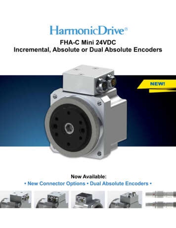
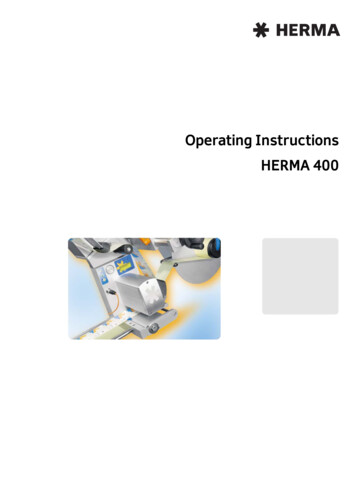
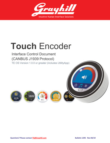
5. Appendix5.1 Programming HarnessQuestions? Please contact TE@Grayhill.comBulletin 1295 Rev 04/19
561 Hillgrove AvenueLa Grange, IL 60525web: www.grayhill.come-mail: te@grayhill.comphone: 1 (708) 354-1040About GrayhillGrayhill, Inc. is a privately held firm which designs and manufacturers intuitive human interface solutions thatmake life simpler, safer, and more efficient. Standard products include optical and Hall Effect encoders,discrete and Hall Effect joysticks, rotary switches, keypads, and pushbuttons; all with finely tuned haptics.Grayhill specializes in creating ergonomic panels and product shells that integrate various interfacetechnologies, including displays, our components, and gesture recognizing multi-touch technology. Withheadquarters in La Grange, Illinois, and multiple state-of-the-art facilities around the world, Grayhill’s team hasthe full engineering, product development and manufacturing expertise to deliver both standard andcustomized products quickly and cost-effectively. To learn more about Grayhill’s products and capabilities, visitwww.grayhill.com.Questions? Please contact TE@Grayhill.comBulletin 1295 Rev 04/19
1. SAE-J1939 2. SAE-J1939/11 3. SAE-J1939/21 4. SAE-J1939/71 5. SAE-J1939/81 . 1.2 Programmable Features (Coming Soon) The following fields can be configured by Grayhill prior to leaving the factory. Requests for custom configuration will be captured in the top-level CAD drawing . Field Name Parameter Type Size (bytes) Range Default Value Comments