Transcription
SURFACEVEHICLERECOMMENDEDPRACTICE rsedingJ1939-21 APR2001Data Link LayerRATIONALEThis SAE Recommended Practice revision incorporates changes to the assigned SAE Reserved Bit to be the ExtendedData Page Bit, Acknowledgement sections, the new proprietary A2 PGN (PGN 126720) and includes new SPNassignments in Appendix D.The 'Reserved' bit of the 29-bit of J1939 header has been defined as the 'Extended Data Page' (EDP) bit. The J1939Subcommittee has concerns there might be existing and developing components for J1939 that don't verify theReserved/EDP bit is zero (0) before processing the 29-bit header per the J1939-21 structure. It is important that existingand future J1939 applications examine the values of the EDP and DP bits before interpreting the remaining 24 bits per thePDU Format (PF), PDU Specific (PS), and Source Address (SA) structure specified in J1939-21.Backward compatibility is maintained during this change by specifying the Extended Data Page bit value of zero for allexisting J1939 PGNs. Prior to this functional change, J1939-21 required the Reserved bit to be set to zero (0) in all J1939PGN Data Frame headers.FOREWORDThis series of SAE Recommended Practices have been developed by the Truck and Bus Control and CommunicationsNetwork Subcommittee of the Truck and Bus Electrical and Electronics Committee. The objectives of the subcommitteeare to develop information reports, recommended practices, and standards concerned with the requirements, design, andusage of devices that transmit electronic signals and control information among vehicle components. The usage of theseRecommended Practices is not limited to truck and bus applications; other applications may be accommodated withimmediate support being provided for construction and agricultural equipment, and stationary power systems.These SAE Recommended Practices are intended as a guide toward standard practice and are subject to change so asto keep pace with experience and technical advances.This data link layer is used for all SAE J1939 applications. It is the characteristic that is common across all SAE J1939applications.SAE Technical Standards Board Rules provide that: “This report is published by SAE to advance the state of technical and engineering sciences. The use of this report isentirely voluntary, and its applicability and suitability for any particular use, including any patent infringement arising therefrom, is the sole responsibility of the user.”SAE reviews each technical report at least every five years at which time it may be reaffirmed, revised, or cancelled. SAE invites your written comments and suggestions.Copyright 2006 SAE InternationalAll rights reserved. No part of this publication may be reproduced, stored in a retrieval system or transmitted, in any form or by any means, electronic, mechanical,photocopying, recording, or otherwise, without the prior written permission of SAE.TO PLACE A DOCUMENT ORDER:SAE WEB ADDRESS:Tel:877-606-7323 (inside USA and Canada)Tel:724-776-4970 (outside USA)Fax:724-776-0790Email: CustomerService@SAE.orghttp://www.SAE.org
标准分享网 www.bzfxw.com 免费下载SAE J1939-21 Revised December 2006TABLE OF 0.2.15.10.2.25.10.2.3Scope . 4References. 4Applicable Publications . 4SAE Publications. 4Related Publications . 4ISO Publications. 4Definitions . 4Abbreviations(R) . 4Technical Requirements . 5Message/Frame Format. 5SAE J1939 Message Frame Format (“CAN 2.0B” Extended Frame Format) (R) . 6Parameter Group Number (PGN) . 6SAE J1939 Support of “CAN 2.0B” Standard Frame Format Messages. 10Protocol Data Unit (PDU). 11Priority (P) . 11Extended Data Page (EDP) (R) . 11Data Page (DP) (R). 11PDU Format (PF) . 14PDU Specific (PS). 14Destination Address (DA) . 14Group Extension (GE). 14Source Address (SA) . 14Data Field. 15Data from 0 to 8 Bytes . 15Data from 9 Up to 1785 Bytes. 15Protocol Data Unit (PDU) Formats . 15PDU1 Format(R) . 16PDU2 Format(R) . 17Message Types. 18Command. 18Request. 18Broadcast/Response. 21Acknowledgment(R). 21Group Function . 23Request2. 25Transfer. 26Message Priority . 27Bus Access . 28Contention-Based Arbitration. 28Error Detection . 28Assignment Process for Source Addresses and Parameter Group Numbers . 28Address Assignment Criteria . 28Parameter Group Assignment Criteria. 29Data Field Definition. 30Transport Protocol Functions. 30Packetization and Reassembly. 30Message Packets. 30Sequence Numbers . 30Packetization. 30Reassembly . 31Connection Management. 31Multipacket Broadcast. 31Connection Initiation . 31Data Transfer . 31Page 2 of 47
SAE J1939-21 Revised December X AAPPENDIX BAPPENDIX CAPPENDIX DConnection Closure . 32Transport Protocol—Connection Management Messages. 33Connection Mode Request to Send (TP.CM RTS). 34Connection Mode Clear to Send (TP.CM CTS). 35End of Message Acknowledgment (TP.CM EndOfMsgACK) . 35Connection Abort (TP.Conn Abort). 35Broadcast Announce Message (BAM). 36Transport Protocol—Data Transfer Message (TP.DT) . 36Connection Constraints. 37Number and Type of Connections a Node Must Support. 37Intended Transport Protocol Use . 37Concurrent PGN Reception . 37PDU Processing Requirements . 37Application Notes . 38High Data Rates. 38Request Scheduling. 38Device Response Time and Timeout Defaults . 38Required Responses . 38Transmission of PGNs to Specific or Global Destinations. 38CTS Number of Packet Recommendation. 39Notes . 39Marginal Indicia . 39SAE J1939 PDU Processing Typical Receive Routine . 40Communication Message Types. 41Transport Protocol Transfer Sequences . 42Assignments of SPNs for J1939-21 . 47LIST OF FIGURESFigure 1 CAN Data Frames(R) . 7Figure 2 Application of OSI Model by SAE J1939(R) . 8Figure 3 Protocol Data Unit(R). 11Figure 4 SAE J1939 Parameter Group Number Template(R). 13Figure 5 Available PDU Formats(R) . 16Figure 6 PDU1 Format (R) . 17Figure 7 PDU2 Format(R) . 18Figure 8 Request PGN Definition (R). 19Figure 9 Acknowledgment PGN Definition (R) . 23Figure 10 Proprietary A PGN Definition (R) . 24Figure 11 Proprietary A2 PGN definition (R) . 25Figure 12 Proprietary B PGN Definition (R) . 25Figure 13 Request2 PGN Format (R) . 26Figure 14 Transfer PGN Format (R) . 27Figure 15 Format of Messages for Transport Protocol (R). 33Figure 16 Transport Protocol—Data Transfer Message (TP.DT) (R). 36Figure A1 Typical Receive Routine. 40Figure B1 Example of Communication Message Types (R). 41Figure C1 Data Transfer without Errors . 42Figure C2 Data Transfer with Errors . 43Figure C3 Broadcast Data Transfer . 44Figure C4 Data Transfer Utilizing RTS Maximum Number of Packets Capability. 45Figure C5 Data Transfer Not Able to Utilize RTS Maximum Number of Packets Capability. 46Table 1Table 2Table 3Table 4LIST OF TABLESMapping of SAE J1939 into CAN’s Arbitration and Control Fields(R) . 9Parameter Group Number Examples (SAE use EDP 0) (R) . 10Definition of Extended Data Page and Data Page Use(R) . 12PDU Specific . 14Page 3 of 47
标准分享网 www.bzfxw.com 免费下载SAE J1939-21 Revised December 2006Table 5 PDU1 and PDU2 Transmit, Request and Response Requirements . 19Table 6 Use of the Specified Fields in SAE J1939 PDU1 Format . 20Table 7 Connection Abort Reason (R). 36Table D1 J1939-21 SPN Usage (R). 471.SCOPEThe SAE J1939 documents are intended for light, medium, and heavy-duty vehicles used on or off road as well asappropriate stationary applications which use vehicle derived components (e.g. generator sets). Vehicles of interestinclude, but are not limited to, on- and off-highway trucks and their trailers, construction equipment, and agriculturalequipment and implements.The purpose of these documents is to provide an open interconnect system for electronic systems. It is the intention ofthese documents to allow Electronic Control Units to communicate with each other by providing a standard architecture.This particular document, SAE J1939-21, describes the data link layer using the CAN protocol with 29-bit Identifiers. ForSAE J1939 no alternative data link layers are permitted.2.REFERENCES2.1Applicable PublicationsGeneral information regarding this series of recommended practices is found in SAE J1939. The latest issue of SAEpublications shall apply.2.1.1SAE PublicationsAvailable from SAE, 400 Commonwealth Drive, Warrendale, PA 15096-0001. Tel: 877 606-7323 (inside USA andCanada) or 724 776 4970 (Outside USA), www.sae.org. Unless otherwise specified, the latest publication shall apply.SAE J1939SAE J1939-71SAE J1939-812.2Recommended Practice for a Serial Control and Communications Vehicle Network is the parentdocument and should be referenced in general.Vehicle Application LayerNetwork ManagementRelated PublicationsThe following publications are provided for information purposes only and are not a required part of this document.2.2.1ISO PublicationsAvailable from ANSI, 25 West 43rd Street, New York, NY 10036-8002, Tel: 212-642-4900, www.ansi.org.ISO 11898 (Amended) Road Vehicles—Interchange of digital information—Controller area network (CAN) for high-speedcommunicationsAMENDMENT 1Road Vehicles—Diagnostics on Controller Area Network (CAN)—Part 3; Implementation of UnifiedISO 15765-3Diagnostic Services (UDS on CAN), October 23, 20033.DEFINITIONSTerms and definitions are defined in SAE ast Announce MessagePage 4 of 47
SAE J1939-21 Revised December ler Area NetworkCyclic Redundancy CheckClear-to-SendDestination AddressData Length CodeData PageData TransferExtended Data PageEnd of FrameGroup ExtensionIdentifierIdentifier Extension BitLogical Link ControlLeast Significant Byte or Least Significant BitMedium Access ControlManufacturerMost Significant Byte or Most Significant BitNot AllowedNegative-AcknowledgmentPriorityProtocol Data UnitPDU FormatParameter Group NumberPDU SpecificRemote Transmission RequestRequest-to-SendSource AddressStart of FrameSuspect Parameter NumberSubstitute Remote RequestTransport ProtocolHold TimeResponse TimeUndefinedTECHNICAL REQUIREMENTSThe data link layer provides for the reliable transfer of data across the physical link. This consists of sending the CANData Frame with the necessary synchronization, sequence control, error control, and flow control. The flow control isaccomplished by a consistent message/frame format.5.1Message/Frame FormatMessage format conforms to the CAN requirements. The CAN specification referenced throughout this document is CANSpecification 2.0 Part B, September 1991. It should be noted that when there are differences between the CANspecification and SAE J1939, then SAE J1939 is the guiding document.Page 5 of 47
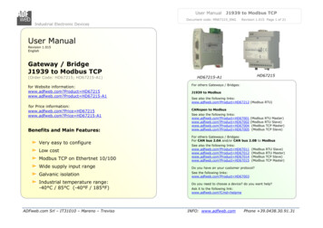
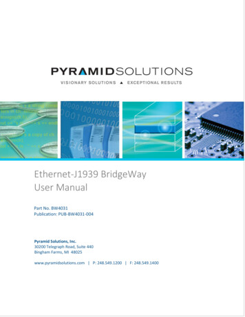
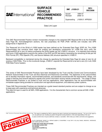
标准分享网 www.bzfxw.com 免费下载SAE J1939-21 Revised December 2006The CAN document specifies, in an information routing related discussion, that node addresses are not used. While thisis true for some applications of CAN, it is not true for SAE J1939. The definition of the SAE J1939 network requires thatnode addressing be used to prevent multiple nodes from using the same CAN Identifier field (see SAE J1939). Manyadditional requirements exist in SAE J1939 that are not specified by CAN.CAN 2.0B contains specification of two message formats, standard frame and extended frame.CAN 2.0B compatibility implies that messages of both formats can potentially be present on a single network by usingcertain bit codings that allow for the recognition of the different formats. To this point, SAE J1939 also hasaccommodations for both CAN data frame formats. But SAE J1939 only defines a full strategy for standardizedcommunications using the extended frame format. All standard frame format messages are for proprietary use followingthe rules defined in this document.Therefore, SAE J1939 devices MUST use the extended frame format. Standard frame format messages can reside onthe network, but only as described in this document.Note Standard frame devices do not respond to network management messages and are not able to support thestrategy for standardized communications.Referencing Figure 1, the CAN data frame is parsed into different bit fields. The number and parsing of the bits in thearbitration and control fields differ between the CAN standard and extended frame messages. CAN standard framemessages, shown in “A,” contains 11 Identifier bits in the arbitration field and CAN extended frame messages, shown in“B,” contain 29 identifier bits in the arbitration field. SAE J1939 has further defined the identifier bits in the arbitration fieldof the CAN Data Frame formats. These definitions can be seen in Table 1.5.1.1SAE J1939 Message Frame Format (“CAN 2.0B” Extended Frame Format) (R)The CAN extended frame message, as shown in Figure 1, encompasses a single Protocol Data Unit (PDU). PDUsconsist of seven predefined fields. These fields are assimilated from information provided by the application layer. Theyare priority, extended data page, data page, PDU format, PDU specific (which can be a destination address, groupextension, or proprietary), source address and data fields. They are then packaged into one or more CAN Data Framesand sent over the physical media to other network devices. The layers of the Open Systems Interconnect (OSI) modelthat SAE J1939 supports are shown in Figure 2. It should be recognized that some Parameter Group definitions requiremore than one CAN Data Frame to send their information.Table 1 shows the arbitration and control fields of the following: 29-bit identifier for CAN; 29-bit identifier for SAE J1939;11-bit identifier for CAN; and the 11-bit identifier for SAE J1939. A complete definition for each of the SAE J1939 bit fieldassignments can be found in the sections that define the SAE J1939 Protocol Data Unit (see Section 5.2). Throughoutthis document the CAN Data Frame data field is discussed as bytes 1 through 8. Byte 1’s most significant bit (bit 8) is thefirst bit sent closest to the DLC field. Byte 8’s least significant bit (bit 1) is last of the data bits to be sent and is closest tothe CRC Field.When the Extended Data Page (EDP) is equal to 1 and the Data Page (DP) is equal to 1, this identifies the CAN frame asan ISO 15765-3 formatted frame. Therefore, the processing of the CAN frame will not follow the definitions provided byJ1939 specifications. The user should consult the ISO 15765-3 specifications for further guidance.For the case where the Extended Data Page is equal to 1 and the Data Page is equal to 0, the SAE J1939 subcommitteehas not specified that the CAN identifier will be utilized the way it is specified in the remaining sections of this document.Therefore, those CAN frames may require unique handling. This will be specified in future versions of the J1939-21document.5.1.2Parameter Group Number (PGN)Whenever it is necessary to identify a Parameter Group in the data field of a CAN data frame, it will be expressed in 24bits. The 24-bit value is sent least significant byte first (see Table 2 where it is stated the MSB is sent third, middle bytesecond and least significant byte first). The Parameter Group Number is a 24-bit value that has the following constituentcomponents: 6 bits set to zero, Extended Data Page bit, Data Page bit, PDU Format Field (8 bits), and Group ExtensionField (8 bits). The procedure for the bit fields to be converted to a Parameter Group Number is as follows. The six mostPage 6 of 47
SAE J1939-21 Revised December 2006significant bits of the PGN are set to zero. Then the Extended Data Page Bit, Data Page bit and PDU Format field arecopied into the next 10 bits. Lastly if the PF value is less than 240 (F016), then the least significant byte of the PGN is setto zero. Otherwise it is set to the value of the Group Extension Field. Reference Table 2 for an illustration of theconstituent component bit fields and their corresponding PGN decimal number. Note that not all 217 (or 131072)combinations are available for assignment using the conventions specified in this document. The conventions specifiedyield 8672 PGs (calculated as: 2 pages * [240 (16*256)] 8672 PGs). The Cumulative Number of PGs column inTable 2 identifies the number of PGNs possible. See SAE J1939, Appendix A to see the assigned PGNs.A. CAN Standard Frame FormatCAN Data FrameMaximum frame length with bit stuffing 127 bitsArbitration Field12 BitsBitsSOF1Control Field6 BitsCRCDelimiterData FieldIdentifierRTRIDEr0DLCData FieldCRC1111140 - 6415ACKFieldEOF271Bit StuffingNo Bit StuffingB. CAN Exte
Canada) or 724 776 4970 (Outside USA), www.sae.org. Unless otherwise specified, the latest publication shall apply. SAE J1939 Recommended Practice for a Serial Control and Communications Vehicle Network is the parent document and should be referenced in general. SAE J1939-71 Vehicle Application Layer SAE J1939-81 Network Management 2.2 Related .