Transcription
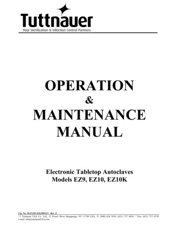
YOUR GUIDE TO MAINTAINING TUTTNAUER M/MK SERIES & VALUEKLAVE MKV STERILIZERSReplacement Parts Industries, Inc. is pleased to present this valuable work tool that can help save you and yourcustomers time and money. Take a look, you will find Troubleshooting Guides, diagrams, exploded views and acomplete listing of all RPI parts that fit all 1730/2340/2540/3850/3870 M/MK and Valueklave 1730 MKV Tuttnauer models. It’sall here, in one easy-to-use tool. Keep it close by –in your RPI catalog or at your workbench.PLEASE NOTE!Over the years, Tuttnauerhas substituted parts fromwhat has been noted in theirLEVELING & FILLING PROCESSmanuals. As a precaution,please verify parts beforeLEVELING THE STERILIZERreplacing or servicing them.1. The sterilizer must be placed on a level surface. Note:When positioning the sterilizer on the surface, be sureto keep the back and right side of the sterilizer approximately 1" (25mm) away from the wall to allow forproper ventilation.2. To check if the sterilizer is level: Refer to Table A, to theright; measure only the amount of water indicated inthe chart for the corresponding model into a measuringcup; and, pour the measured water into the chamber.The water must reach the indication groove near thefront of the chamber. Refer to Figure 1, to the right.If the water does not reach or it goes past the groove,the sterilizer is not level and must be adjusted. To helplevel the sterilizer, use the RPI Wrench (Low Profile) (RPIPart #RXT003) to adjust the front legs of the sterilizer.FILLING THE RESERVOIR1. Use distilled water only to fill the reservoir. Fill the reservoir until the water level is 1" (25mm) below the base ofthe Safety Valve Holder. Refer to the Min/Max lines on theReservoir Dip Stick.Caution! For proper operation of the sterilizer,do not fill water above the Safety Valve Holder.FIGURE 1LEVELING THE STERILIZERTo verify that the sterilizer islevel, the amount of water (asindicated in Table A, to theright) when poured into thechamber must reach the indication groove inside the chamber.TABLE AAMOUNT OF WATER NEEDED, TO CHECK IF STERILIZER IS LEVEL.ModelAmount of Water1730 Series & Valueklave 1730 MKV2340 & 2540 Series3870 Series10 - 12 oz. (300 - 360 ML)12 - 15 oz. (360 - 440 ML)24 - 27 oz. (710 - 800 ML)INDICATIONGROOVEService Tip: To easilyadjust the feet, use theWrench (Low Profile)(RPI Part #RXT003).PLANNED MAINTENANCECAUTION!DAILYBefore starting any maintenance or repairs: 1) Turn the sterilizer OFF. 2) Disconnect the sterilizer from the power source beforeservicing. Follow all local, NEC and OSHA safety guidelines. 3) Verify that there is no pressure in the unit. 4) Allow to cool to roomtemperature. 5) Wear appropriate protective hand and eye gear.Clean the Door Gasket with a soft cloth or sponge using a soft liquid detergent and water. Rinse well and leave no residue.WEEKLY 1. Remove the Trays and Tray Holder from the unit. Clean the Chamber, Tray Holder and Trays with a cloth or sponge using an OEMrecommended cleaner. Caution: Do not use steel wool, a steel brush or chlorinated cleansers on these parts.2. Thoroughly rinse Chamber, Tray Holder, and Trays with clean water. Flush the Chamber. Flush the Fill hole located at the backof the Chamber by turning the Fill Knob to the FILL position for a couple of seconds.3. Dry the Chamber, Tray Holder and Trays, and reinstall. Place a couple of drops of oil on the two door pins and the door tightening bolts. Clean the outside of the unit with a soft cloth or sponge using a non-abrasive cleaner. Drain and flush the Water Reservoir while using a baby bottle brush to clear any build up of debris. Refill the reservoir (seeFILLING THE RESERVOIR, above). When the sterilizer is cold and not pressurized, verify the integrity of the Spring and Plunger Assembly by pulling and releasingthe end ring on the Safety Valve – it should spring back. Remove and clean Chamber Filters. Check and clean the Air Jet Valve by moving the wire back and forth several times to prevent debris buildup.MONTHLY During a sterilization cycle, use an insulated tool or pair of needle nose pliers to pull on the end ring of the Safety Valve, and let thesteam exhaust for a couple of seconds. This will remove debris in the lines and clean the valve's orifices. Verify its closing ability.Caution: During this procedure, be prepared for a rush of steam to be released with a loud hissing sound. Wear appropriateprotective hand and eye gear. After Every 20 Cycles - Clean Sterilizer with Tutt-Clean (RPI Part #'s TUC094 &TUC095) in conjunction with the SterilizersCleaning Kit (RPI Part #RPK791) to help remove water deposits, oxides and other sediments.ANNUALLYRecommended parts to be replaced at this time include the Door Gasket, Chamber Filters, Door Bellows, and parts showing wear. PMKits are a convenient package that include all of the parts that need to be replaced on an annual basis, see page 11.The parts mentioned in this document are manufactured by Replacement Parts Industries, Inc. to fit Tuttnauer equipment.1All product names used in this document are trademarks or registered trademarks of their respective holders. RPI, 2019 (Rev C 06/19)
EXPLODED VIEWTUK075 - RESERVOIR COVER WITH DIPSTICKTUC067 - WATER RESERVOIR/FILTER COVERTUS068 - WATER RESERVOIR DIPSTICKTUT155OVERTEMPTHERMOSTAT(SEE PAGE 10)TUH015 (X3)HARDWARE KITTUH004HEATER ELEMENTHEATERS(SEE PAGE 10)TUS035OVER-TEMP SWITCH(SEE PAGE 10)PCN136TUB072TUT073TAPTUS014TUS146DOOR SHIM(3800 SERIES ONLY)TUK030DOOR BELLOWSASSEMBLY PCN13620259200102391000Papsi/F400DOOR GASKETS(SEE PAGE 10)PM KITS(SEE PAGE 11)PRESSURE GAUGES(SEE PAGE 10)TUF0582ALIGN PAGE 3 WITH THIS EDGE FOR A COMPLETE "EXPLODED VIEW OF STERILIZER"TUH052HEATER HARDWARE
OF STERILIZERPCN136TUC028 (115V)RPC582 (220V)RPH659CIRCUIT BREAKERS(SEE PAGE 10)ALIGN PAGE 2 WITH THIS EDGE FOR A COMPLETE "EXPLODED VIEW OF STERILIZER"TUT038 (MANUAL RESET)SAFETY THERMOSTAT(SEE PAGE 10)WIRE HARNESS(SEE PAGE 10)RPR583TUT038 (MANUAL RESET)SAFETY THERMOSTATS(SEE PAGE 10)TUT039 (AUTO RESET)TUG110PRESSURE GAUGE (TEST)VENTPORTTUT039 (AUTO RESET)SAFETY THERMOSTAT(SEE PAGE 10)CIRCUITBREAKERS(SEE PAGE 10)TUG022TUF079ELBOWFITTINGMIF062(2 pcs)TUK055SAFETY VALVE ANDSAFETY VALVE HOLDER(SEE PAGE 10)FILLPORTCONDENSATION COILS(SEE PAGE 10)TUS009TUT007PRESSUREGAUGES(SEE PAGE 10)TUT008TUV025 - MULTI-PURPOSE VALVE(TUV097 & TUV098 NOT SHOWN)TUK037 - MPV REPAIR KIT(TUK099 NOT SHOWN)SEE PAGE 9 & i/F400TUP062TUK050TUK049MDL022 (115V)TUL137 (220V)MDL021 (115V)TUL136 (220V)Use for PressureVerification in SterilizersUse to Re-tap BellowsHousing in DoorPressure Gauge (Test)RPI Part #TUG110(OEM Part #TEST-2)Includes Pressure Gauge (RPI Part#RPG693), Guage Guard (RPI Part#RPG694), Male Connector (RPIPart #RPF688), and Tube Adapter(RPI Part #RPF689).Tap (3/8 BSPP Threads)RPI Part #TUT073(OEM Part #TEST-3)Use a standard 9/16" open endwrench or a 5/8" socket as a handtap wrench. Includes a durableplastic storage case.MICRO-SWITCHES(SEE PAGE 9)(SEE PAGE 10)Use for TemperatureVerification in SterilizersMax. Register ThermometerRPI Part #RPT113(No OEM Part # Available)Size: .40" OD x 6.63" lg.Accuracy Rating: 1 Division( 2 F); Dual Scale: 150 F to 350 F(65 C to 177 C). Includes metalprotective case.3Use on Leveling Feetand Air Jet ValvesWrench (Low Profile)RPI Part #RXT003(OEM Part #MW03-0002)Stainless steel double ended flatwrench: 7/16" x 10mm. Used forleveling feet and air jet valves.
BASIC PLUMBING CONFIGURATIONSLEFT SIDE MULTI-PURPOSE VALVE MOUNT UNITS MANUFACTURED BEFORE 1993RIGHT SIDE MULTI-PURPOSE VALVE MOUNT UNITS MANUFACTURED AFTER 1993HEATING ELEMENT SERVICE TIPS When replacing a Heater, a burning smell may be present for several cycles. This is normal and does not indicate any malfunction of the newHeater. Current Heaters offered by RPI and Tuttnauer are designed to accommodate Safety Thermostats that use 3/16" diameter bulbs. Whenreplacing the Heater band that mounts the Safety Thermostats to theChamber, take a moment to measure the diameter of the SafetyThermostat bulbs. If the bulbs are 1/8" diameter (original style), then replace them with the newer style 3/16" diameter bulbs to ensure propercontact to the Chamber and the Heater band. Make sure that the bulb for the automatic reset Safety Thermostat is installed in the lower groove of the heater band, and that the bulb for themanual reset thermostat is installed in the upper groove.4 When installing new heater bands, note that there are two different heaterband closing clamp mechanisms; a three bolt/"flange" pattern, and a "Tbolt" and barrel pattern.– When installing the three bolt/"flange" pattern, it is important to tightenall (3) three bolts evenly until the band is snug against the chamber.– When installing the "T-bolt" and barrel pattern, you only need to tightenthe single bolt until the band is snug against the chamber.Also note, on this style heater band, there is a large cutout in the band.This cutout is for the old-style over temperature devices, modern unitswill still use the capillary-tube-style over temperature devices locatedin the ridges just below the cutout.With both styles of heater bands, it is important to run the sterilizer throughseveral test cycles and then retighten the hardware to ensure a properfit. Failing to properly tighten the heater bands can lead to a prematurefailure.
ELECTRICAL TROUBLESHOOTING& WIRING DIAGRAMSSERVICE TIPWhen working on theelectrical system, followall safety requirements.BASIC CIRCUIT INSPECTION1. Disconnect power to unit.2. Set sterilizer controls to the following settings: Circuit Breaker ON Power Switch ON Sterilizer Door CLOSED Timer Set for more than 10 minutes Temperature Controller Set at 250º or higher3. Set a multi-meter to ohm scale, then connect the line and neutral terminalsof the power module.4. Rotate the Multi-Purpose Valve to each setting; starting and ending at O, andobserve the meter for the following: In the STE and EXH DRY positions, the meter should read the circuit values( 10%) shown in Table B, below for each model. If the VOM meter readsoutside the 10%, then you must check each individual heating elementby disconnecting one of the wires going to the heating element terminalsand measuring across the two terminals. Verify the resistance needed foreach individual heating element by comparing it to the required resistancelisted for your unit in Table B, below. If any heating element is outside ofthe required resistance by 10%, then it must be replaced.5. Remove unit's covers and insulation blanket. Perform a full visualinspection of wiring, terminals and connections. Inspect the wiringharness for loose leads and broken or damaged wires. Make any repairs andretest. If no defects found, then inspect eachcomponent and conduct continuity check of the complete wiring circuit.6. Refer to the schematic in Figure 2, below, check each circuit component,starting with the circuit breaker. Take note of the following characteristics foreach of the components: Safety Thermostats should be closed except at high temperature when theyopen to protect the circuit. Note: Models built after January, 1993 havedual Safety Thermostats, one of which has a manual reset button and islocated near the circuit breaker. Timer must be turned past 10 minutes to make contact and provide electrical continuity. Control Thermostat must be set above 212 F to make contact andprovide electrical continuity. Microswitch wiring is referenced in Figure 2, below. Microswitch positionsare shown on page 9, MULTI-PURPOSE VALVE & MICROSWITCHES. (Note:Microswitches are best checked with an analog ohm meter.) Heater element resistance values are shown in Table B, below.7. Repair or replace all faulty circuits or components, then retest unit.8. Replace insulation blanket and reinstall covers.9. Run unit for several cycles and check all operations.TABLE B - APPROXIMATE CIRCUIT VALUES ( 10%) AT STE AND EXH-DRY POSITIONS & APPROXIMATE HEATER ELEMENT RESISTANCE VALUES ( 10%)Model1730M1730M1730MK1730MKV 0500500Individual HeatingElement 96.088.088.0105.8105.8FIGURE 2Schematic of Current Tuttnauer Models 2340M/MK & 2540M/MKAlthough the schematic below applies to the current 2340M/MK & 2540M/MKModels of Tuttnauer sterilizers, it can be used as a reference for all of theother manual models as well. Variations to the wiring of manual models iscommon among Tuttnauer sterilizers. For a list of the variations that mightbe encountered when servicing these sterilizers, see the listing to the right.Resistancein 61010101313Resistancein 21123223225533Variations Between Tuttnauer M/MK/MKV Wiring Single vs. Dual Circuit Breakers Circuit Breaker(s) or Fuse Holder Single or Dual Thermostat Wiring of Thermostat (Manual or Automatic reset) Wiring of Heat Light or Dry Light With or without Door Switch Number of Heating Elements requiredLEGEND (Located on Multi-Purpose Valve)MSW1 Microswitch 1 MSW2 Microswitch 2 MSW3 Microswitch 3See PAGE 9 for Microswitch positions5
WATER/STEAM SYSTEMTROUBLESHOOTINGWater and steam leaks not only cause damage to the site where the unit is located but also,will create a low water condition resulting in overheating that could cause major damage to the autoclave.SERVICE TIPTo help preventclogging of the MPV,install RPI Filters (RPIPart #MIF062) intothe Water Fill andExhaust Lines.ISOLATING LEAKS & CORRECTIVE ACTIONHOW TO CHECK THE AIR JET VALVEVisual and audible leaks can bedetected by operating the sterilizerSERVICE TIPin the normal STE mode withIf the Chamber is found to betemperature set at 273º F anddefective, tag it as "Out ofthe time set for 30 minutes on MOperation". Removal of theunits and 15 minutes on MK &power cord is recommendedValueklave 1730 MKV units.until the chamber is replaced.Possible points of water/steamleaks with corrective action, andorder in which they should be checked are noted in #1-5 below.1. Refer to Table A, page 1, and in a measuring cup, fill it with the amount ofwater indicated in the chart for the corresponding model, then pour themeasured water into the Chamber.2. Bypass the FILL setting to manually run sterilizer in STE mode at 273 Ffor 30 minutes for M units and 15 minutes for MK & Valueklave 1730MKV units. After 30 minutes (or 15 minutes), shut off power, but leaveMPV in STE mode until chamber pressure is reduced to 0 PSI and chamberhas cooled (approx. 15 minutes).3. Open Chamber Door, siphon water back into the measuring cup, andmeasure the amount of water remaining in the chamber.- If remaining water is less than 50% of the original volume and no otherleaks were detected, replace Air Jet Valve.- If remaining water is greater than 50% and the pressure did not reachwithin the nominal times (see STERILIZATION TIMES, page 9), and nofault was found within the heating system, then replace the Air Jet Valve.1DOOR GASKET & DOOR BELLOWSCheck chamber Door Gasket for any steam leaks, hissing, or waterbubbles at the Door Bellows. If steam is leaking at the door closingdevice, then rotate the Gasket 180 to see if the leak follows it. If theleak follows the Gasket, then replace the Gasket. If the leak does notfollow the Gasket, then replace the Door Bellows. (Also available is aDoor Shim (RPI Part #TUS146) made of stainless steel to install behindthe Door Gasket to fit the 3800 Series only.)2REMOVING OBSTRUCTIONSHOW TO UNCLOG THE MULTI-PURPOSE VALVE DURING A CYCLE1. Refer to Table A, page 1, and pour the indicated amount of water intothe sterilizer. Turn the power switch ON.2. Close and lock the sterilizer door – be sure to make a tight seal and waitfor the heat light to come on.3. Set the sterilizer to the following settings: Multi-Purpose Valve (MPV) setto STE position; Timer Knob set to 20 minutes; and, Thermostats Knob to273 F (134 C). Then press power switch to START. (Note: With the MPV inthe STE position, heaters will be ON, and sterilizer will begin to build pressure.)4. When the Chamber pressure reaches 30-31 PSI: Turn the Power Switch to the OFF position. Turn the MPV to the FILL position. Now the Chamber pressure shouldforce out debris from the MPV through the Fill Line into the Reservoir. When the pressure in the Chamber reaches 0, turn the MPV to the OFFposition, then open the door. Allow the sterilizer to cool. Clean out any debris from the inside of the Chamber. If the MPV is still clogged, rebuild or replace it.SAFETY VALVERemove the Water Reservoir Fill Cover and visually inspect the SafetyValve – use a dental mirror to help locate the leak. Confirm that there isno steam or water drops escaping from the vent holes or threadsof the Safety Valve. If a leakage is observed, replace the Safety Valve.3AIR JET VALVEInspect the Air Jet Valve. It should make a slight hissing soundthroughout the STE cycle. If there is excessive hissing, steam, orwater bubbles escaping from the Air Jet Valve, refer to HOW TO CHECKTHE AIR JET VALVE, at the top right hand side of this page. ServiceTip: Use a dental mirror to help locate the leak.HOW TO MANUALLY UNCLOG THE MULTI-PURPOSE VALVE1. Disconnect power from sterilizer. Allow to cool. Remove covers.2. At the center port of the Multi-Purpose Valve (MPV), disconnect thefitting. Set MPV to the FILL position. Service Tip: Drain most of the waterfrom the Reservoir to prevent excess spillage during this process. Thiswill also verify that the Drain Tube and Drain Valve are clear. If water flows into the Chamber, then the obstruction has been clearedfrom MPV and Fill Tube. If water does not flow into the Chamber, check Fill Tube as follows:Disconnect Fill Tube fitting at bottom of MPV.- If water flows, Fill Tube is clear, but MPV must be rebuilt or replaced.- If water does not flow, use forced air through Fill Tube and check forbubbles in Reservoir. If procedure does not clear obstructions, replaceFill Tube. Service Tip: When disconnecting Fill Tube, straighten portionof tube (about 1" lg.) that protrudes into the bottom of Reservoir.Support Reservoir boss with a wrench.3. If MPV and Fill Tube are clear, next check Chamber Tube as follows:Disconnect and remove MPV from Chamber Tube. Use forced air or waterthrough tube. If procedure does not clear obstructions, replace ChamberTube. Also check and clear Chamber Fitting and boss of any obstructions.4. Check exhaust lines as follows: At the top port of MPV, disconnectCondensing Coil Tube, see MULTI-PURPOSE VALVE, page 9. Force airthrough tube. If the flow is blocked, determine whether Condensing Coilor Tube is obstructed. Clear obstruction or replace coil and/or tube.5. If no leaks or obstructions have been found by following the previous steps,and sterilizer is still experiencing a low water condition resulting inoverheating problems, see HOW TO CHECK THE AIR JET VALVE, above.If a water/steam leak is not related to #1-3 above, disconnect power fromthe sterilizer and remove the cover, then carefully remove theinsulation blanket. Proceed to #4-5, below. Warning! Make sure powerhas been disconnected prior to removing the cover. When running thesterilizer with the cover removed, the interior of the machine will bevery hot - use extreme caution.4MULTI-PURPOSE VALVEInspect the Multi-Purpose Valve for leakage. Note any leaks at the threefittings or the valve stem. If none are found, disconnect theCondensation Coil in the water reservoir at the point where it connectsinside the reservoir. Operate the sterilizer in STE mode at 273 Ffor 30 minutes on M units and 15 minutes on MK & Valueklave1730 MKV units, and look for any signs of leakage back into thereservoir from the tubing fitting where the Condensation Coil wasattached. Inspect the water fill tube at the bottom of the reservoir forany signs of steam bubbling back into the reservoir. If any leakage isnoted at either position, repair or replace the Multi-Purpose Valve.Important: Reconnect Condensation Coil before exhausting Chamberpressure.5CHAMBER & INTERNAL TUBINGCarefully inspect for steam or water bubbles at the Chamber and allfittings. If a leak is detected at one of the fittings or tubing, tightenor replace only after the unit has been depressurized and allowed tocool down.6
TROUBLESHOOTINGSYMPTOMPower-On Light does not illuminateCAUSESOLUTIONSWall outlet or plugVerify power at outlet. Make sure power cordis plugged in at the wall and at the machine.Power SwitchCircuit BreakerTurn Power Switch ON. Replace if necessary.Reset breaker. Check for short circuit (see page 5). If no shortis found, replace Circuit Breaker (see page 10).Power LampReplace Power Light.Open CircuitCheck for loose or disconnected wires. Replace Wire Harness,if necessary (see page 10).TimerCheck that Timer is turned ON. Timer must be advancedpast 10 minutes to activate.Heat LampIf unit has heat and pressure, check and/or replace Heat Lamp (seepage 10). If unit has no heat, check for open circuit (see page 5).Microswitch 1 (MSW1) is defectiveor it is stuck in the down position.Check MSW1. Adjust or replace as necessary (see page 9).Control ThermostatSet Control Thermostat to 212 F or higher. Adjust or replaceControl Thermostat as necessary.Heat lamp is ON; No heat or pressureHeatersMeasure Heater for proper resistance, see Table B, page 5. Checkfor broken/disconnected wiring. Replace if necessary (see page 10).Heat lamp is ON in STE cycle, butwith low heat and slow pressurebuildSteam LeakCheck for audible/visual steam leak at Door Gasket, Door Bellows,Safety Valve, Air Jet Valve, and Condensation Coil. If there are airbubbles in reservoir, check Multi-Purpose Valve. Repair or replacefaulty part(s) as necessary.HeatersMeasure Heaters for proper resistance, see Table B, page 5.Check for broken or disconnected wiring.Control ThermostatSet Control Thermostat to 212 F or higher. Adjust or replaceControl Thermostat as necessary.Excess water in ChamberCheck water level. Check level of unit per Installation Procedure,see Figure 1, page 1.Pressure GaugeCheck and/or replace Pressure Gauge (see page 10).Control ThermostatReset Control Thermostat to proper value or, if necessary,replace it.Safety ValveIf Safety Valve opens below rated cracking pressure, replace it.Water levelCheck fill operation and water level, see Figure 1, page 1.Water or steam leakCheck for audible/visual steam leak at Door Gasket, Door Bellows,Safety Valve, Air Jet Valve, and Condensation Coil. If there are airbubbles in reservoir, check Multi-Purpose Valve. Repair or replacepart(s) as necessary.Unit overheats, Power and Heat Lightsgo outLow water level(Over Temp Safety Switch)Check for water or steam leak. Replace Over Temp SafetySwitch if necessary (see page 10).Heat lamp remains ON when Timer isat 0 or Timer will not advanceTimerTimer must be advanced past 10 minutes to activate.Check Timer operation and replace if necessary.Timer Bell does not soundTimerTimer must be advanced past 10 minutes to activate.Check Timer operation and replace if necessary.Water enters Chamber after unit isexhausted and the door is closedCondensation CoilWater level is above open end or there is a hole in the Condensation Coil creating a vacuum. Reduce water level to 1" below SafetyValve and open end of Condensation Coil must be above waterlevel. Replace Condensation Coil if necessary (see page 10).Multi-Purpose Valve(if not stuck open)Remove, disassemble, clean and rebuild, or replace Multi-PurposeValve (see MULTI-PURPOSE VALVE, page 9 and 10).Heat Lamp OFF in STE cycleSafety Valve opensUnit overheats, Heat Light stays ON7
TROUBLESHOOTINGMulti-Purpose Valve Assembly (MPV)IMPORTANT NOTE! Before working on the Multi-Purpose Valve or the Door Bellows: Disconnect the sterilizer from the power sourcebefore servicing. Follow all local, NEC and OSHA safety guidelines. Wear protective hand and eye gear. Use a tool such as a screwdriver orwrench (do not use your fingers) to pull the Safety Valve Pull Ring, and vent the Chamber to ZERO pressure. Allow the unit to cool down.SYMPTOMCAUSESOLUTIONMPV will not rotate.MPV is jammed.Remove, disassemble, clean and rebuild, or replace MPV.See Important Note!, above.MPV valve rotates in both directions.Broken Anti-rotational SpringClip.Remove, disassemble, clean and rebuild, or replace MPV (see IMPORTANT NOTE!, above and REMOVING OBSTRUCTIONS, page 6)MPV will not exhaust in the EXH-DRYposition; Pressure remains highClogged MPV, Condensation Coil, orMPV Tubing.Remove, disassemble, clean and rebuild, or replace MPV (see IMPORTANT NOTE!, above and REMOVING OBSTRUCTIONS, page 6)With power ON, MPV in EXH-DRY; DryLight is OFF, but unit is drying properlyDry Light malfunction.Replace Dry Light.With power ON, MPV in EXH-DRY; Unitis not drying properlyExcess water in Chamber.If Chamber door is closed, then open the door 1" to allow forproper ventilation.Chamber over packed.Refer to Owners Manual for maximum load.Heater malfunction.Measure Heater for proper resistance, see Table B, page 5.Check for broken/disconnected wiring. Replace if necessary.Timer not activated.Activate Timer by setting it past 10 minutes. If timer still doesnot activate, then replace Timer.Microswitch 1 (MSW1) is defectiveor it is stuck in the down position.Set MPV to STE position, if Heat Light is OFF, adjust or replaceMSW1. Refer to MULTI-PURPOSE VALVE & MICROSWITCHES, page 9.Microswitch 2 (MSW2) is defectiveor it is stuck in the down position.Set MPV to STE position, if Heat Light is OFF, adjust or replaceMSW2. Refer to MULTI-PURPOSE VALVE & MICROSWITCHES, page 9.In EXH-DRY position, Dry and HeatLights OFF (Door open)Microswitch 3 (MSW3) is defectiveor it is stuck in the up position.Adjust or replace MSW3. Refer to MULTI-PURPOSE VALVE &MICRO-SWITCHES, page 9.In EXH-DRY position, Circuit Breakertrips when Timer is set.Microswitch 2 (MSW2) is defectiveor it is stuck in the up position.Adjust or replace MSW2. Refer to MULTI-PURPOSE VALVE &MICRO-SWITCHES, page 9.Short circuit in Wiring Harness.Check and replace Wiring Harness or repair shorted wire, seepage 10.With power ON, MPV in EXH-DRY position, all three lights ON (indicating unitis overheating).Microswitch 3 (MSW3) is defectiveor it is stuck in the up position.Adjust or replace MSW3. Refer to MULTI-PURPOSE VALVE &MICRO-SWITCHES, page 9.Door will not open after Chamber is exhausted and MPV is in the EXH-DRY positionDoor Bellows could be jammed.1) See Important Note!, above. Then turn door closing deviceslightly clockwise to tighten, then turn counter clockwise to open.In EXH-DRY position, Power Light is ON,Dry Light OFF, but unit is not drying2) See Important Note!, above. Remove covers. Carefully movethe Insulation Blanket on the left side to expose the ChamberTightening Bolt. Loosen Bolt until Door Locking Assembly isloose enough to open the Door. After the Door is open, tightenthe Bolt and replace the Insulation Blanket. If necessary,replace Door Bellows Assembly, see page 2.Vacuum in Chamber (pressurebelow zero).8See Important Note!, above. If this does not correct thesituation, then check if MPV has blockage, see page 6,REMOVING OBSTRUCTIONS.
MULTI-PURPOSE VALVE (MPV)Illustrations shown below refer to right side MPV mount onlyNOTE: The illustrations below show the Multi-Purpose Valve (RPI Part #TUV025). The Multi-PurposeValves (RPI Part #'s TUV097 & TUV098) have slightly different connection fittings and orientations.See page 10 for the models that these valves fit.TOP VIEWM SERIESCONNECTION TOTHE CHAMBERSIDE VIEWCYCLE TYPE:COLD START:HOT START:Unwrapped30 minutes20 minutesCYCLE TYPE:COLD START:HOT START:Wrapped40 minutes30 minutesCYCLE TYPE:COLD START:HOT START:Packs45 minutes35 minutesMK SERIES & VALUEKLAVE 1730 MKVCONNECTION TOWATER RESERVOIR (EXHAUST LINE)POSITION OF VALVE ATSTE (STERILIZE) MODECONNECTION FROMWATER RESERVOIR(FILL LINE)MSW1MSW2MSW3CENTER PORTNEW STYLE MICROSWITCH OPERATIONCLOSED SWITCH ACTIVATED OPEN SWITCH NOT ACTIVATEDSWITCH LOSEDCYCLE TYPE:COLD START:HOT START:Unwrapped15 minutes12 minutesCYCLE TYPE:COLD START:HOT START:Wrapped20 minutes15 minutesCYCLE TYPE:COLD START:HOT START:Packs25 minutes20 minutes The sterilization times noted above arebased on the information sticker located onthe unit's outer covering. If the voltage issignificantly less than the voltage noted,then additional time must be added to eachcycle to ensure proper functionality.MOUNTING BRACKET0FILLSTEEXH-DRYTotal Time from Start to FinishSTE Temperature: 273 F (134 C)60 - 65 FLAT ON SHAFT ATSTE (STERILIZE)POSITIONVALVE POSITIONSTERILIZATION TIMES Tuttnauer sterilizers tend to run a few degrees higher than the set temperature.MSW3OPENOPENOPENCLOSEDMICROSWITCHESNo Longer AvailableCOM. TABRPI Part #TUS013RPI Part #TUS057N.C. TABN.O. TABN.C. TABN.O. TABCOM. TABN.C. TABN.O. TABCOM. TABMicroswitch (CHERRY E11/GREY)Microswitch (CHERRY E13/BLACK)Microswitch (CHERRY D48X/GREY)RPI Part #TUK061Microswitch KIT (NEW STYLE)SERVICE TIP: If unit is to be upgraded from the old style Microswitches (Cherry E11 or E13) to thenew style Microswitch (Cherry D48X/Grey), then the Microswitch Kit (RPI Part #TUK061) must beused. The Kit includes the spacers and hardware that are necessary to upgrade from the old styleto the new style MICROSWITCHES.9
COMMON PARTS QUICK REFERENCECONDENSATION COILSCIRCUIT BREAKERSRPI Part #TUB023TUB024TUB048TUB047StyleLeverLeverPush ButtonPush ButtonOptions15 AMPS10 AMPS7 AMPS15 AMPSFUSE & FUSE HOLDERRPI Part # DescriptionRPF071Fuse (15A)RPH659Fuse HolderFits ModelsFits all modelsFits all modelsGASKETSRPI Part # Fits ModelsTUG0011730M/MK &Valueklave 1730 MKVTUG00223
Models of Tuttnauer sterilizers, it can be used as a reference for all of the other manual models as well. Variations to the wiring of manual models is common among Tuttnauer sterilizers. For a list of the variations that might be encountered when servicing these sterilizers, see the listing to the right. Variations Between Tuttnauer M/MK/MKV .