Transcription
User GuideTracer CH530 Control System for ChillersRTWD/RTUD 060-250RLC-SVU05A-E4
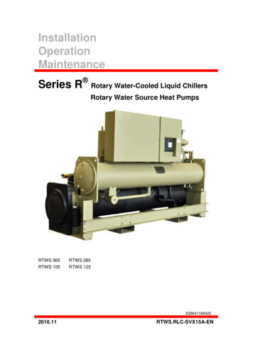
General informationForewordWarnings and cautionsReceptionThese instructions are given as aguide to good practice in theinstallation, start-up, operation, andmaintenance by the user, of TraneCH530 chiller control system onchillers. They do not contain fullservice procedures necessary forthe continued successful operationof this equipment. The services of aqualified technician should beemployed through the medium of amaintenance contract with areputable service company. Readthis manual thoroughly before unitstart-up.Warnings and Cautions appear atappropriate sections throughoutthis manual. Your personal safetyand the proper operation of thismachine require that you followthem carefully. The constructorassumes no liability for installationsor servicing performed byunqualified personnel.On arrival, inspect the unit beforesigning the delivery note.WARNING! : Indicates a potentiallyhazardous situation which, if notavoided, could result in death orserious injury.CAUTION! : Indicates a potentiallyhazardous situation which, if notavoided, may result in minor ormoderate injury. It may also beused to alert against unsafepractices or for equipment orproperty-damage-only accidents.Safety recommendationsTo avoid death, injury, equipmentor property damage, the followingrecommendations should beobserved during maintenance andservice visits:1. Disconnect the main powersupply before any servicing onthe unit.2. Service work should be carriedout only by qualified andexperienced personnel. 2009 TraneReception in France only:In case of visible damage: Theconsignee (or the siterepresentative) must specify anydamage on the delivery note,legibly sign and date the deliverynote, and the truck driver mustcountersign it. The consignee (orthe site representative) must notifyTrane Epinal Operations - Claimsteam and send a copy of thedelivery note. The customer (or thesite representative) should send aregistered letter to the last carrierwithin 3 days of delivery.Reception in all countries exceptFrance:In case of concealed damage: Theconsignee (or the siterepresentative) must send aregistered letter to the last carrierwithin 7 days of delivery, claimingfor the described damage. A copyof this letter must be sent to TraneEpinal Operations - Claims team.Note: for deliveries in France, evenconcealed damage must be lookedfor at delivery and immediatelytreated as visible damage.RLC-SVU05A-E4
General informationWarrantyTrainingWarranty is based on the generalterms and conditions of themanufacturer. The warranty is voidif the equipment is repaired ormodified without the writtenapproval of the manufacturer, if theoperating limits are exceeded or ifthe control system or the electricalwiring is modified. Damage due tomisuse, lack of maintenance orfailure to comply with themanufacturer's instructions orrecommendations is not covered bythe warranty obligation. If the userdoes not conform to the rules ofthis manual, it may entailcancellation of warranty andliabilities by the manufacturer.To assist you in obtaining the bestuse of it and maintaining it inperfect operating condition over along period of time, themanufacturer has at your disposal arefrigeration and air conditioningservice school. The principal aim ofthis is to give operators andtechnicians a better knowledge ofthe equipment they are using, orthat is under their charge. Emphasisis particularly given to theimportance of periodic checks onthe unit operating parameters aswell as on preventive maintenance,which reduces the cost of owningthe unit by avoiding serious andcostly breakdown.Maintenance contractIt is strongly recommended that yousign a maintenance contract withyour local Service Agency. Thiscontract provides regularmaintenance of your installation bya specialist in our equipment.Regular maintenance ensures thatany malfunction is detected andcorrected in good time andminimizes the possibility thatserious damage will occur. Finally,regular maintenance ensures themaximum operating life of yourequipment. We would remind youthat failure to respect theseinstallation and maintenanceinstructions may result inimmediate cancellation of thewarranty.RLC-SVU05A-E43
ContentsGeneral Information2Overview5DynaView Interface6Display Screens8Diagnostics28TechView Interface54Software Download455RLC-SVU05A-E4
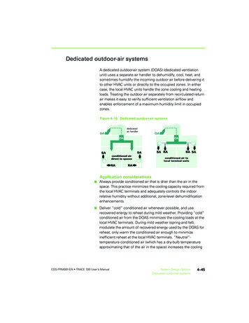
OverviewThe Trane CH530 control systemthat runs the chiller consists ofseveral elements: The main processor collectsdata, status, and diagnosticinformation and communicatescommands to the LLID (for LowLevel Intelligent Device) bus. Themain processor has an integraldisplay (DynaView). LLID bus. The main processorcommunicates to each input andoutput device (e.g. temperatureand pressure sensors, lowvoltage binary inputs, analoginput/output) all connected to afour-wire bus, rather than theconventional control architectureof signal wires for each device. The communication interface toa building automation system(BAS). A service tool to provide allservice/maintenance capabilities.Main processor and service tool(TechView) software isdownloadable fromwww.Trane.com. The process isdiscussed later in this sectionunder TechView Interface.DynaView provides busmanagement. It has the task ofrestarting the link, or filling in forwhat it sees as "missing" deviceswhen normal communicationshas been degraded. Use ofTechView may be required.The CH530 uses the IPC3 protocolbased on RS485 signal technologyand communicating at 19.2 Kbaudto allow 3 rounds of data persecond on a 64-device network.Most diagnostics are handled by theDynaView. If a temperature orpressure is reported out of range bya LLID, the DynaView processes thisinformation and calls out thediagnostic. The individual LLIDs arenot responsible for any diagnosticfunctions.Note: It is imperative that the CH530Service Tool (TechView) be used tofacilitate the replacement of anyLLID or reconfigure any chillercomponent.Controls InterfaceDynaView (picture on cover)Each chiller is equipped with theDynaView interface. DynaView hasthe capability to display additionalinformation to the advancedoperator including the ability toadjust settings. Multiple screens areavailable and text is presented inmultiple languages as factoryordered or can be easilydownloaded online.TechViewTechView can be connected to theDynaView module and providesfurther data, adjustmentcapabilities, diagnosticsinformation, downloadablesoftware, and downloadablelanguages.RLC-SVU05A-E45
DynaView InterfacePower UpOn power-up, Dynaview willprogress through 3 screens.The first screen (Figure 1) willdisplay for 3-10 seconds. Thisscreen will give the status of theApplication software, the BootSoftware P/N, selftest results andthe application part number. Thecontrast is adjustable from thisscreen. The message "Selftestpassed" may be replaced with "Err2:RAM Error" or "Err3: CRC Failure"Note that the Application and Bootsoftware numbers will varyaccording to the unit type.If no application is found, the screen(Figure 2) will display instead ofFigure 1.Figure 1Figure 26RLC-SVU05A-E4
DynaView InterfaceThe second screen (Figure 3) willdisplay for 15-25 seconds. If a validconfiguration is present, "TracerCH530" will also be displayed. If theMP configuration is found to beinvalid, "MP: Invalid Configuration"is displayed indefinitely. Contactyour local Trane service technician.The third screen is the first screenof the application.Figure 3Figure 4RLC-SVU05A-E47
DynaView InterfaceThe display on DynaView is a1/4 VGA display with a resistivetouch screen and an LED backlight.The display area is approximately4 inches wide by 3 inches high(102mm x 60mm).CAUTION!Equipment Damage! Puttingexcessive pressure on the touchscreen could cause damage. It takesless than 7 kg of force to break thescreen.In this touch screen application, keyfunctions are determinedcompletely by software and changedepending upon the subject mattercurrently being displayed. The basictouch screen functions are outlinedbelow.Radio ButtonsRadio buttons show 1 menu choiceamong 2 or more alternatives, allvisible. The possible selections areeach associated with a button. Theselected button is darkened,presented in reverse video toindicate it is the selected choice.The full range of possible choicesas well as the current choice isalways in view.Spin Value ButtonsSpin values are used to allow avariable setpoint to be changed,such as leaving water setpoint. Thevalue increases or decreases bytouching the ( ) or (-) arrows.Action ButtonsAction buttons appear temporarilyand provide the user with a choicesuch as Enter or Cancel.File Folder TabsFile folder tabs are used to select ascreen of data. The tabs are in1 row across the top of the display.The user selects a screen ofinformation by touching theappropriate tab.Figure 5 - Basic Screen FormatDisplay ScreensThe main body of the screen is usedfor description text, data, setpoints,or keys (touch sensitive areas). TheChiller Mode is displayed here.A double arrow pointing to the rightindicates more information isavailable about the specific item onthat same line. Pressing it will bringyou to a sub-screen that willpresent the information or allowchanges to settings.98RLC-SVU05A-E4
DynaView InterfaceThe bottom of the screen (7) ispresent in all screens and containsthe following functions. Thecontrast (8,9) may require readjustment at ambienttemperatures significantly differentfrom those present at lastadjustment. The other functions arecritical to machine operation. TheAUTO and STOP keys are used toenable or disable the chiller. Thekey selected is in black (reversevideo). The chiller will stop whenthe STOP key is touched and aftercompleting the Run Unload mode.Touching the AUTO key will enablethe chiller if no diagnostic ispresent. (A separate action must betaken to clear active diagnostics.)The AUTO and STOP keys takeprecedence over the Enter andCancel keys. (While a setting isbeing changed, AUTO and STOPkeys are recognized even if Enter orCancel has not been pressed.) TheALARMS button appears only whenan alarm is present, and blinks (byalternating between normal andreverse video) to draw attention toa diagnostic condition. Pressing theALARMS button takes you to thecorresponding tab for additionalinformation.Note: screens may differ accordingto unit type or configuration. Theyshould be considered as examples.Keypad/Display LockoutFeatureNote: The DynaView display andTouch Screen Lock screen is shownabove. This screen is used if theDisplay and touch screen and lockfeature is enabled. Thirty minutesafter the last keystroke, this screenis displayed and the Display andTouch Screen is locked out until thesequence "159 ENTER " ispressed. Until the proper passwordis entered, there will be no accessto the DynaView screens includingall reports, setpoints, andAuto/Stop/Alarms/Interlocks. Thepassword "159" can not be changedfrom either DynaView or TechView.For setting changes, use thepassword "314 ENTER ".System/Circuit Selection ButtonsOn some report and setting screens,radio buttons on the top of thescreen shall be presented to allowthe user to select subscreens basedon system-level data and per-circuitdata.Figure 6 - Keypad1RLC-SVU05A-E4For single-circuit units withsystem/circuit selection buttons, thebuttons shall be labeled (in English)“System” and “Ckt”. For two-circuitunits with system/circuit selectionbuttons, the buttons shall belabeled “System”, “Ckt1”, and“Ckt2”.9
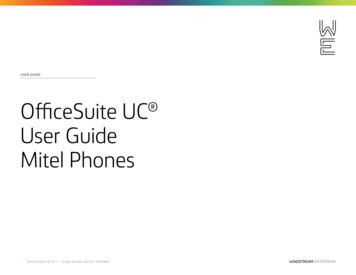
DynaView InterfaceThe Main screen shall be the defaultscreen. After an idle time of30 minutes the CH530 shall displaythe Main screen with the first datafields. The remaining items (listedin the following table) will beviewed by selecting the up/downarrow icons.Main ScreensThe Main screen is a “dashboard”of the chiller. High level statusinformation is presented so that auser can quickly understand themode of operation of the chiller.The Chiller Operating Mode willpresent a top level indication of thechiller mode (i.e. Auto, Running,Inhibit, Run Inhibit, etc.) The“additional info” icon will present asubscreen that lists in further detailthe subsystem modes.Figure 7 - Main screenMainReportsChiller Mode:RunningCircuit 1 Mode:Running - LimitCircuit 2 Mode:AutoEvap Ent / Lvg Water Temp:12 / 7 CCond Ent / Lvg Water Temp:30 / 35 CActive Chilled Water Setpoint:Auto10Settings7CStopRLC-SVU05A-E4
DynaView InterfaceTable 1 - Main Screen Data Fields er Mode ( submodes)enumeration2.Circuit 1 Mode ( submodes)enumeration3.Circuit 2 Mode ( submodes)enumeration4.Evap Ent/Lvg Water TempF/C0.15.Cond Ent/Lvg Water TempF/C0.16.Active Chilled Water Setpoint ( source) ( front panel setpoint) from arbitration setpoint screenF/C0.17.Active Hot Water Setpoint ( source) ( front panelsetpoint) - from arbitration setpoint screenF/C0.18.Average Line Current%RLA19.Active Current Limit Setpoint ( source) ( front panelsetpoint) - from arbitration setpoint screen% RLA110.11.Active Ice Termination Setpoint( front panel setpoint)F/C0.1If Ice Building Option is installed12.Outdoor Air TemperatureF/C0.1Only if OA sensor is installed13.Software TypeenumerationRTWD / RTUD14.Software VersionChiller ModeThe machine-operating modeindicates the operational status ofthe chiller. A subscreen withadditional mode summaryinformation will be provided byselection of an additionalinformation icon ( ). Theoperating mode line will remainstationary while the remainingstatus items scroll with the up/downarrow keys.Active Chilled Water Setpoint andActive Hot Water SetpointThe active chilled water setpoint isthe setpoint that is used in coolmode. The active hot water setpointis the setpoint that is used in heatmode. Both setpoints result fromthe logical hierarchy of setpointarbitration by the main processor.The water setpoint will be displayedto 0.1 degrees Fahrenheit orCelsius.RLC-SVU05A-E4Water Cooled only (i.e. RTWD orRTUD with ACFC None
(TechView) software is downloadable from www.Trane.com. The process is discussed later in this section under TechView Interface. DynaView provides bus management. It has the task of restarting the link, or filling in for what it sees as "missing" devices when normal communications has been degraded. Use of TechView may be required.