Transcription
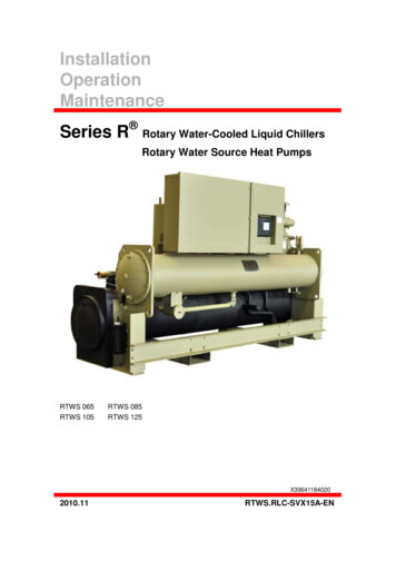
InstallationOperationMaintenanceSeries R Rotary Water-Cooled Liquid ChillersRotary Water Source Heat PumpsRTWS 065RTWS 105RTWS 085RTWS 125X396411840202010.11RTWS.RLC-SVX15A-EN
ATTENTION:Warnings and Cautions appear at appropriate sections throughout this literature. Readthese carefully.WARNING: Indicates a potentially hazardous situation which, if not avoided,could result in death or serious injury.CAUTION: Indicates a potentially hazardous situation which, if not avoided,could result in minor or moderate injury. It may also be used to alert against unsafepractices.NOTICE: Indicates a potential situation which, if not avoided, may resultin equipment or property damage-only accidents, or possible environment pollution. It alsoprovides useful and helpful information that may benefit to a better unit operation or alonger usage life. But it doesn’t deem a best practice or a direct effect on benefit to unitoperation.ImportantEnvironmental Concerns!Scientific research has shown that certain man-made chemicals can affect theearth’s naturally occurring stratospheric ozone layer when released to theatmosphere. In particular, several of the identified chemicals that may affectthe ozone layer are refrigerants that contain Chlorine, Fluorine and Carbon(CFCs) and those containing Hydrogen, Chlorine, Fluorine and Carbon(HCFCs). Not all refrigerants containing these compounds have the samepotential impact to the environment. Trane advocates the responsiblehandling of all refrigerants—including industry replacements for CFCs suchas HCFCs and HFCs.Responsible Refrigerant Practices!Trane believes that responsible refrigerant practices are important to theenvironment, our customers, and the air conditioning industry. All technicianswho handle refrigerants must be certified. The Federal Clean Air Act (Section608) sets forth the requirements for handling, reclaiming, recovering andrecycling of certain refrigerants and the equipment that is used in theseservice procedures. In addition, some states or municipalities may haveRTWS.RLC-SVX15A-EN
additional requirements that must also be adhered to for responsiblemanagement of refrigerants. Know the applicable laws and follow them.WARNINGContains Refrigerant!System contains oil and refrigerant under high pressure. Recover refrigerantto relieve pressure before opening the system. See unit nameplate forrefrigerant type.Do not use non-approved refrigerants, refrigerant substitutes, or refrigerantadditives.Failure to follow proper procedures or the use of non-approved refrigerants,refrigerant substitutes, or refrigerant additives could result in death or seriousinjury or equipment damage.WARNINGPersonal Protective Equipment (PPE) Required!Always refer to appropriate MSDS and OSHA guidelines when handlingfluorocarbon refrigerants. Use proper breathing, eye, and body protectionduring the handling of fluorocarbon refrigerants. Failure to follow properhandling guidelines could result in death or serious injury.WARNINGLive Electrical Components!During installation, testing, servicing and troubleshooting of this product, itmay be necessary to work with live electrical components. Have a qualifiedlicensed electrician or other individual who has been properly trained inhandling live electrical components perform these tasks. Failure to follow allelectrical safety precautions when exposed to live electrical componentscould result in death or serious injury.RTWS.RLC-SVX15A-EN
ContentsContents1 Model Number Description。。。。。。。。。。。12 General 。73 ��。。。。94 Unit �115 Installation - Mechanical。。。。。。。。。。。。156 Installation - 37 RTWS Operating Principles。。。。。。。。。。。598 Controls �。。689 Pre-Start 11810 Unit Start-Up Procedures。。。。。。。。。。。12311 Unit 。。13112 Maintenance and Service。。。。。。。。。。。13313 。。。。14914 Wiring ��180
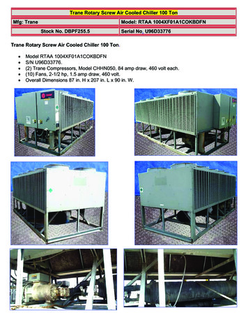
1 Model Number Description1.1 OverviewThis manual covers the installation, operation and maintenance of the RTWS units.1.2 NameplatesThe RTWS unit nameplates are applied to the exterior surface of the control panel door.A compressor nameplate is located on compressor.1.2.1 Unit NameplateThe unit nameplate (Figure1.1) provides the following information: Unit model and size descriptor. Unit serial number. Identifies unit electrical requirements. Lists correct operating charges of R-134a and refrigerant oil. Lists unit design pressures Identifies installation, operation and maintenance and service data literature. Lists drawing numbers for unit wiring diagrams.Figure1.1 Unit Nameplate1.2.2 Compressor Nameplate1RTWS.RLC-SVX15A-EN
Model Number DescriptionThe compressor nameplate provides the following information: Compressor model number. Compressor serial number. Compressor electrical characteristics. Utilization range. Recommended refrigerant.1.2.3 Pressure Vessel NameplatesThe pressure vessel nameplate is different for the evaporators, condensers and oilseparators (RTWS only). The evaporator/condenser nameplates are located on the leftportion of the shells. The insulation over the nameplates is intentionally left unglued, forease in viewing the nameplate. The oil separator nameplate is on shell of oil separatorshell also.Figure1.2 Location of Pressure Vessel Nameplates (front)CondenserNameplate2RTWS.RLC-SVX15A-EN
Model Number DescriptionFigure1.3 Location of Pressure Vessel Nameplates (back)Oil separatorNameplateEvaporator Nameplate1.2.4 Model Number Coding SystemThe model numbers for the unit and the compressors are comprised of numbers and letterwhich represent features of the equipment.Each position or group of positions, in the number is used to represent a feature. Forexample, Unit voltage contains the number “C”. From the chart, it can be seen that a “C” inthis position means that the unit voltage is 380/50/3.Figure1.4 RTWS Model Number3 Taicang, ChinaDigit 01, 02, 03, 04 – Chiller ModelRTWS Water Cooled Chiller Series R Digit 10, 11 – Design SequenceSimplexA0 First design **** First Design, etc. increment when parts areDigit 05, 06, 07 – Unit Nominal Tonnageaffected for service purposes065 65 Nominal Tons085 85 Nominal TonsDigits 12 – Unit Type105 105 Nominal Tons1 Standard Efficiency/Performance125 125 Nominal TonsDigit 13 – Agency ListingDigit 08 – Unit Voltage/Unit Hertz0 No Agency ListingC 380/50/3C Manufactured to GB StandardsE 400/50/3Digit 14 – Pressure Vessel CodeS Special1 ASME Pressure Vessel CodeDigit 09 – Manufacturing Plant3 Chinese Code Pressure Vessel3RTWS.RLC-SVX15A-EN
Model Number DescriptionDigit 15 – Unit ApplicationS SpecialA Standard Cond 45 C(113 F) Leaving WaterDigit 26 – Compressor Starter TypeTempY Wye-Delta Closed Transition StarterB High Temperature Cond 45 C(113 F)X Across the Line StarterLeaving Water TemperatureC Water-to-Water Heat PumpDigit 27 – Power Line Connection TypeS SpecialA Terminal Block Connection for Incoming LinesB Mechanical Disconnect SwitchD Circuit BreakerDigit 16 – Pressure Relief ValveDigit 28 – Under/Over VoltageProtection2 Dual Relief Valve with 3-Way Isolation ValveDigit 17 – Water Connection Type0 No Under/Over Voltage ProtectionB Flanged Connection1 Under/Over Voltage ProtectionS SpecialDigit 29 – Unit Operator InterfaceDigit 18 – Evap ApplicationA Dyna-View/English1 Standard CoolingM Dyna-View/Thai2 Low TemperatureN Dyna-View/Simplified Chinese3 Ice MakingDigit 30 – Remote Interface (DigitalCommunication)Digit 19 – Evap TubesA Internal and External Enhanced Evap Tube0 No Remote Digital CommunicationDigit 20 – Number of Evap Passes1 LonTalk/Tracer Summit Interface2 2 Pass Evap2 Time of Day Scheduling3 3 Pass Evap3 Unit Level BACnet4 LonTalk LCI-C Interface w/ Modbus interfaceDigit 21 – Evap Waterbox ConnectionDirection1 Right In Right OutDigit 31 – External Water & CurrentLimit Setpoint2 Right In Left Out0 No External Water & Current-Limit SetpointA External Water & Current-Limit Setpoint -Digit 22– Evap Water Side Pressure4–20 mAA 10.4 Bar (150 psi) Evap Water PressureB External Water & Current-Limit Setpoint -S Special2–10 VdcDigit 23 – Cond TubesDigit 32 – Ice MakingA Enhanced Fin - Copper0 No Ice MakingS SpecialA Ice Making with RelayDigit 24 – Cond Waterbox ConnectionDirectionB Ice Making without RelayDigit 33 – Programmable Relays1 Right In Right Out2 Left In Left Out0 No Programmable RelaysA Programmable RelaysDigit 25 – Cond Water Side PressureDigit 34 – Cond Refrigerant Pressure1 10.4 Bar( 150 psi) Cond Water Pressure4RTWS.RLC-SVX15A-EN
Model Number DescriptionOutput OptionC 4” 150 psi/114.3 mm 10.4 bar 115V0 No Cond Pressure OutputD 4” 150 psi/114.3 mm 10.4 bar 220V1 Cond Pressure OutputS Special2 Cond Pressure (%HPC) OutputDigit 42 – Sound Reduction Package3 Differential Pressure Output0 No Sound Reduction PackageDigit 35 – Outdoor Air Temp Sensor0 No Outdoor Air Temp SensorDigit 43 – InsulationA Outdoor Air Temp Sensor-CWR0 No InsulationDigit 36 – Cond Leaving Hot WaterTemp Control1 Factory Insulation - All Cold Parts2 Insulation for High Humidity0 No Cond Leaving Hot Water TemperatureDigit 44 – Factory ChargeControl0 Full Factory Refrigerant Charge (R134a)1 Cond Leaving Hot Water Temperature Control1 Nitrogen ChargeDigit 37 – Power MeterDigit 45 – Base Rail Fork Lifting0 No Power Meter0 No Base Rail Fork LiftingP Power MeterB Base Rail Fork LiftingDigit 38 – Motor Current Analog Output(%RLA)Digit 46 – Label and LiteratureLanguage0 No Motor Current Analog OutputD English1 Motor Current Analog OutputF Chinese – SimpleDigit 39 – Installation AccessoriesDigit 47 – Special0 No Installation Accessories0 NoneA Elastomeric IsolatorsS SpecialDigit 40 – Flow SwitchDigit 48 – Shipping Package1 150 psi NEMA 1; Flow Switch x10 No skid (Standard)2 150 psi NEMA 1; Flow Switch x21 Skid3 150 psi NEMA 4; Flow Switch x14 150 psi NEMA 4; Flow Switch x2Digit 49 – Performance Test Options7 Factory Installed Proof of Flow Evap & Cond0 No Performance TestS SpecialC 1 Point Test with ReportD 2 Point Test with ReportDigit 41 – 2-Way Water Regulating ValveG Witness 1 Point Test With Report0 No 2-Way Water Regulating ValveH Witness 2 Point Test With ReportA 3” 150 psi/88.9 mm 10.4 bar 115VB 3” 150 psi/88.9 mm 10.4 bar 220V5RTWS.RLC-SVX15A-EN
Model Number DescriptionFigure1.5 Compressor Model Number (located on compressor nameplate)6RTWS.RLC-SVX15A-EN
2 General Information2.1 Unit DescriptionThe RTWS units are helical-rotary type, water-cooled, liquid chillers, designed forinstallation indoors. The units have one refrigerant circuit with one compressor. TheRTWS units are packaged with an evaporator and condenser.Note: Each RTWS unit is a completely assembled, hermetic package that isfactory-piped, wired, leak-tested, dehydrated, charged and tested for proper controloperations prior to shipment. The chilled/cooling water inlet and outlet openings arecovered for shipment.The RTWS series features Trane's exclusive Adaptive Control logic with CH530 controls.It monitors the control variables that govern the operation of the chiller unit. AdaptiveControl logic can correct these variables, when necessary, to optimize operationalefficiencies, avoid chiller shutdown, and keep producing chilled water.Compressor unloaders are solenoid actuated. The refrigerant circuit is provided with filter,sight glass, electronic expansion valve, and charging valves on the RTWS.The evaporator and condenser are manufactured in accordance with GB 151-1999Shell-Tube Heat Exchanger. The evaporator is fully insulated. Both evaporator andcondenser are equipped with water drain and vent connections.2.2 Accessory/Options InformationCheck all the accessories and loose parts which are shipped with the unit against theoriginal order. Included in these items will be water vessel drain plugs, rigging diagrams,electrical diagrams, and service literature, which are placed inside the control panel and/or starter panel for shipment. Also check for optional components, such as flow switchesand isolators.7RTWS. RLC-SVX15A-EN
General Information2.3 General DataTable2.1 General Data - 50 Water Storage(L)29.835.748.555.6(gal)7.99.412.814.7Two Pass ArrangementWater Conn. SizeMinimum FlowMaximum 596115(L/s)13.817.322.326.5(gpm)218274353420Three Pass ArrangementWater Conn. SizeMinimum FlowMaximum Two Pass Arrangement)Water StorageWater Conn. SizeMinimum FlowMaximum 21.4(L)9.39.310.710.7(quarts)8.48.49.79.7General UnitRefrigerant Type# Refrig CircuitRefrigerant ChargeOil Charge1. Flow limits are for water only8RTWS. RLC-SVX15A-EN
3 Pre-Installation3.1 Inspection ChecklistWhen the unit is delivered, verify that it is the correct unit and that it is properly equipped.Compare the information which appears on the unit nameplate with the ordering andsubmittal information. Refer to “Nameplates”.Inspect all exterior components for visible damage. Report any apparent damage ormaterial shortage to the carrier and make a “unit damage” notation on the carrier'sdelivery receipt. Specify the extent and type of damage found and notify the appropriateTrane Sales Office.Do not proceed with installation of a damaged unit without sales office approval.To protect against loss due to damage incurred in transit, complete the following checklistupon receipt of the u
The RTWS series features Trane's exclusive Adaptive Control logic with CH530 controls. It monitors the control variables that govern the operation of the chiller unit. Adaptive Control logic can correct these variables, when necessary, to optimize operational efficiencies, avoid chiller shutdown, and keep producing chilled water.