Transcription
DC-8AIRBORNE LABORATORYEXPERIMENTER HANDBOOK817NASANational Aeronautics and Space AdministrationDryden Flight Research CenterEdwards, CA 93523-0273
This page left blank intentionally.
NASADC-8, AIRBORNE LABORATORYEXPERIMENTER HANDBOOKTABLE OF CONTENTSCH/PAGEINTRODUCTION/NOMENCLATURE . 1CHAPTER 1 . 1-1AIRCRAFT PERFORMANCE . 1-1Basic Aircraft Performance . 1-1Frequency and Duration of Flights . 1-7Cabin Environment . 1-8Aircraft Stability . 1-8Aircraft Attitude . 1-8Worldwide Capability . 1-9CHAPTER 2 . 2-1COMMUNICATION AND NAVIGATION . 2-1Basic Equipment and Operation . 2-1Navigation Accuracy . 2-3Navigation Planning . 2-5Radar Tracking Beacons . 2-5CHAPTER 3 . 3-1INTERIOR DIMENSIONS AND SUPPORT FACILITIES . 3-1General Information . 3-1Cabin and Cargo Areas . 3-1Fuselage Access . 3-10Support Facilities . 3-13CHAPTER 4 . 4-1FUSELAGE VIEWPORTS AND WINDOWS . 4-1General Information . 4-1General Description . 4-1Configuration Details . 4-4Special Inserts . 4-4Optical Windows . 4-5External Airflow Parameters . 4-16CHAPTER 5 . 5-1EXPERIMENT CONSTRUCTION AND INSTALLATION . 5-1General Information . 5-1General Arrangement . 5-1i
NASADC-8, AIRBORNE LABORATORYEXPERIMENTER HANDBOOKCH/PAGEConstruction Guidelines . 5-2Aircraft Vibration . 5-6Structural Attachments . 5-9Standard Equipment Racks . 5-19Mounting Techniques . 5-22Equipment Certification . 5-33Hazardous Equipment and Materials Certification . 5-34CHAPTER 6 . 6-1ELECTRICAL POWER . 6-1General Information . 6-1Power Sources and Frequency Converters . 6-1Experimenters’ Power Stations . 6-2Batteries . 6-6Uninterruptible Power Systems (UPS) . 6-8Aircraft Ground System (AGS) . 6-9Electromagnetic Interference (EMI) . 6-9Electrical Safety . 6-10Heaters . 6-13Experiment Cabling . 6-14Equipment Certification . 6-14CHAPTER 7 . 7-1INFORMATION COLLECTION AND TRANSMISSION SYSTEM (ICATS) . 7-1General Information . 7-1Overview of ICATS . 7-1Data Sources for the ICATS System . 7-3Output Parameters From ICATS . 7-5Video Distribution of ICATS . 7-6RS-232 Data Line to Experimenter-operator Computers . 7-6On-deployment Data Delivery Available After Flight . 7-7Dryden-based ICATS Post-flight Data Delivery and Archiving . 7-7CHAPTER 8 . 8-1FACILITY INSTRUMENTATION . 8-1General Information . 8-1Standard Aircraft Systems . 8-1Camera Systems . 8-5Dropsonde System . 8-8Satellite Weather Pictures . 8-8Time Information . 8-9ii
NASADC-8, AIRBORNE LABORATORYEXPERIMENTER HANDBOOKCH/PAGECHAPTER 9 . 9-1FLIGHT OPERATIONS . 9-1Flight Safety . 9-1Flight Management . 9-6CHAPTER 10 . 10-1GROUND OPERATIONS . 10-1General Definition . 10-1Experiment Assembly and Checkout . 10-1Installation of Experiments . 10-5The Flight Period . 10-8Post-flight Activities . 10-8APPENDIX A . A-1GUIDELINES FOR EXPERIMENTER RACK LOADING . A-1Guidelines . A-1Examples . A-4APPENDIX B . B-1DFRC AIRBORNE SCIENCE CRYOGENIC HANDLING PROCEDURES . B-1Scope . B-1Purpose . B-1Equipment Requirements . B-1General Properties . B-1Labeling . B-2Pressure Relief . B-2Hazards of Oxygen Deficiency . B-3Hazards of Air-Freezing Cryogens . B-3Hazards of Carbon Dioxide Toxicity . B-4Hazards of Oxygen Enrichment . B-4Personal Protective Equipment . B-5Immediate Treatment for Frostbite . B-6Training Procedures and Safety Notes . B-6APPENDIX C . C-1OUTPUT PARAMETERS FROM ICATS . C-1Introduction . C-1Data From Time Code Generator . C-1Data From Honeywell Embedded GPS/INS 1553 Bus . C-2Data From Radar Altimeter 1553 Bus . C-4Data From Navigational Management System ARINC-429 . C-4Data From Air Data Computer ARINC-429 . C-7Data From Global Positioning System (GPS) ARINC-429 . C-7Data From Analog Sources and Computed Functions . C-8iii
NASADC-8, AIRBORNE LABORATORYEXPERIMENTER HANDBOOKCH/PAGEAPPENDIX D . D-1ICATS SERIAL OUTPUTS TO EXPERIMENTS . D-1Introduction . D-11200 Baud. D-19600/19.2K Baud . D-2Parameter Format Information. D-6RS232 Format Key . D-6FIGURE LISTFigure 1-1(a). General view and over-all dimensions of the DC-8. . 1-2Figure 1-1(b). General view and over-all dimensions of the DC-8. . 1-3Figure 3-1. Plan and side views of the aircraft, overview . 3-2Figure 3-1(a). Section A . 3-3Figure 3-1(b). Section B . 3-4Figure 3-1(c). Section C . 3-5Figure 3-1(d). Section D . 3-6FIgure 3-2. Antenna locations and identification . 3-7FIgure 3-2(a). Section A . 3-8Figure 3-2(b). Section B . 3-9Figure 3-3. Cross section of the fuselage . 3-11Figure 3-4. Cabin and cargo area access doors . 3-12Figure 3-5. Mission director’s console . 3-14Figure 4-1. Viewport information. . 4-2Figure 4-2. Typical 62 viewports and nadir 5 and 9 . 4-6Figure 4-3. Typical 8 viewport. . 4-7Figure 4-4. Typical zenith viewport. . 4-8Figure 4-5. Nadir no. 7 viewport (nadir no. 2 similar) . 4-9Figure 4-6(a). Optical viewport, frame and glass dimensions . 4-10Figure 4-6(b). Optical viewport, frame and glass dimensions . 4-11Figure 4-7. Standard unmodified passenger window . 4-12Figure 4-8. Radiometer on 8 insert panel . 4-13Figure 4-9. Optical characteristics of standard unmodified passenger windows . 4-15Figure 5-1(a). In-flight vibration spectra . 5-7Figure 5-1(b). In-flight vibration spectra . 5-8Figure 5-1(c). In-flight vibration spectra . 5-9Figure 5-2. Seat rails and clamps . 5-10Figure 5-3. Loads for a standard rack and connectors . 5-12Figure 5-4(a). Standard equipment racks – high rack . 5-13Figure 5-4(b). Standard equipment racks – high rack – dimensions . 5-14Figure 5-5(a). Standard equipment racks – medium rack . 5-15Figure 5-5(b). Standard equipment racks – medium rack – dimensions . 5-16iv
NASADC-8, AIRBORNE LABORATORYEXPERIMENTER HANDBOOKCH/PAGEFigure 5-6(a). Standard equipment racks – low rack . 5-17Figure 5-6(b). Standard equipment racks – low rack – dimensions . 5-18Figure 5-7. Installed equipment racks and viewports, cross section . 5-20Figure 5-8. Typical installation in equipment rack . 5-21Figure 5-9. Typical tray mounting configurations . 5-23Figure 5-10. Typical equipment mounting techniques – 62 Viewport . 5-24Figure 5-11. Typical equipment mounting techniques – low rack . 5-25Figure 5-12. Large experimenter equipment mounted on special framework . 5-27Figure 5-13. Large experimenter equipment mounted on special framework . 5-28Figure 5-14(a). Typical wing tip pylon . 5-29Figure 5-14(b). Typical wing tip pylon . 5-30Figure 5-15. Wing tip connector panel in main cabin – station 670 . 5-31Figure 6-1. Typical power and intercom station in cabin . 6-3Figure 6-2(a). Typical rack power panel . 6-5Figure 6-2(b). Rack power panel receptacles . 6-6Figure A-1(a). Low rack. A-2Figure A-1(b). Medium rack. A-3FIgure A-1(c). High rack . A-3Figure A-2. Standard face mounted equipment . A-4Figure A-3. Configuration examples and flow chart . A-5TABLE LISTTable 1-1. Maximum aircraft range with normal fuel reserves . 1-1Table 1-2(a). Mission duration and initial altitude for 20,000 lb payload . 1-4Table 1-2(b). Mission duration and initial altitude for 30,000 lb payload . 1-5Table 1-3. True airspeed envelope . 1-6Table 1-4. DC-8 turn radius in NM, as a function of airspeed and bank angle. 1-6Table 2-1. Frequencies and interferences. 2-2Table 2-2. Radio systems specifications . 2-3Table 4-1. Location, aperture size, and load capacity of viewports. 4-3Table 4-2. Minimum thickness of window materials . 4-14Table 4-3. Inviscid flow over passenger ports, relative to fuselage floor plan . 4-17Table 4-4. Inviscid flow over 62 ports, relative to vertical centerline andfuselage floor planes . 4-18Table 4-5. Inviscid flow over nadir ports, relative to vertical centerline andfuselage floor planes . 4-18Table 5-1. Minimum crash load design criteria. 5-3Table 5-2. Minimum pressure vessel design criteria . 5-4Table 6-1. Commonly encountered wire/cable insulation materials . 6-12Table 8-1. Standard aircraft data systems available on CCTV and ICATS data stream. 8-2Table 8-2. Supplemental data systems . 8-6Table A-1. Basic loading allowables for low, medium, and high racks. A-2Table A-2. Allowable loading for face-mounted equipment. A-6v
This page left blank intentionally.vi
NASADC-8, AIRBORNE LABORATORYEXPERIMENTER HANDBOOKINTRODUCTIONSince August 1987, NASA has been operating A Douglas DC-8-72 Aircraft (NASA 817)for research activities in earth, atmospheric, and space sciences. This aircraft,extensively modified as a flying laboratory, is based at Dryden Flight Research Center(DFRC), Edwards, California. It is operated for the benefit of researchers whoseproposals have been previously approved by NASA Headquarters. Airborne laboratoryflights may be operated out of DFRC or from deployment sites worldwide, according tothe research requirements.The DC-8 is a four-engine jet aircraft with a range in excess of 5,000 nmi (9,200 km), aceiling of 41,000 ft (12,500 m), and an experiment payload of 30,000 lb (13,600 kg).Utilization is planned to be 350 to 500 flight hours per year. Special viewports, powersystems, and instruments have been installed in the aircraft to support a wide range ofresearch programs.Airborne research missions for the DC-8 are planned, implemented, and managed bythe Airborne Science Directorate at DFRC. A designated mission manager is responsiblefor all phases of an assigned mission and is the official point of contact for experimentersas well as for ground support and flight operations groups. The mission manager leads acore team, specific to each mission, consisting of him/herself, an operations engineer, aproject pilot, and the contract maintenance lead. This team makes all significantdecisions regarding mission aircraft operations. The mission manager also functions asthe onboard mission director during flight phases of the mission. The mission directorcoordinates and monitors science and operations activities on the aircraft during flights.The purpose of this handbook is to acquaint prospective DC-8 researchers with theaircraft and its capabilities. The handbook also contains procedures for obtainingapproval to fly experiments, outlines requirements for equipment design and installation,and identifies the personnel and facilities that are available at DFRC for supportingresearch activities in the DC-8 airborne laboratory. This handbook is managed andrevised from time to time by the DFRC Airborne Science Directorate. Therefore, beforearranging for experiments it is advisable to review the web site listed below, then contactthe DFRC Airborne Science Directorate or your assigned mission manager for a currentissue.For information about the overall DFRC Airborne Science Program, including aircraftschedules and Airborne Science flight request procedures, and for an electronic versionof this and other experimenter handbooks, look on the World Wide Web omenclaturePage 1June 2002
NASADC-8, AIRBORNE LABORATORYEXPERIMENTER GPSGSHFHPICATSIDLHILSINSIRIRIGKTASalternating currentair data computerautomatic direction finderautomated external defibrilatorautomatic picture transmission systemtext formatAir Traffic Controlbest computed positionclosed circuit televisioncontrol display unitscontiguous United Statescentral processing unitdirect currentdata communications equipmentDryden Centerwide ProcedureDryden Flight Research Centerdistance measuring equipmentdata terminal equipmentExperiment Integration Facilityelectromagnetic interferenceemergency passenger oxygen system (or smoke hood)Federal Aviation Administrationflight management systemground fault interrupterGreenwich Mean TimeGlobal Positioning Systemglideslope receiverhigh frequencyhorsepowerinformation collection and transmission systemimmediately dangereous to life or healthinstrument landing systeminertial navigation systeminfraredInter-Range Instrument Groupknot, true airspeedIntroduction/NomenclaturePage 2June 2002
NASADC-8, AIRBORNE LABORATORYEXPERIMENTER CPARM UHFUPSUTCVDCVHFVORWWGSlocalizer receivermulti-function displaymilitary standardmilitary specificationsMaterial Safety Data SheetNational Aerospace StandardNational Aeronautics and Space AdministrationNational Electrical Manufacturers Associationnautical milenavigational management systemNational Oceanic and Atmospheric AdministrationNational Television Standards Committeeparameter identification codeParticle Measuring Systemspolyvinyl chlorideradio frequencyResearch Instrumentation Branchstatic air temperaturesatellite communications systemsealed lead acidsuper video home systemtactical air navigation transmitter/receivertrue air speedtotal air temperaturetraffic alert and collision avoidance systemtime code generatorthreshold limit valueultra high frequencyuninterruptible power systemsCoordinated Universal Timevolts of direct currentvery high frequencyVHF omnidirectional rangerwattsWorld Geodetic SystemIntroduction/NomenclaturePage 3June 2002
This page left blank intentionally.Introduction/NomenclaturePage 4June 2002
NASADC-8, AIRBORNE LABORATORYEXPERIMENTER HANDBOOKCHAPTER 1AIRCRAFT PERFORMANCE1.Basic Aircraft PerformanceThe NASA DC-8-72, serial no. 46082 (NASA 817), is similar in appearanceand performance to other four-engine, standard-body jet transports, asshown in figure 1-1(a) and 1-1(b). The aircraft is powered by four CFMInternational, CFM56-2-C1, high bypass ratio turbofan engines developinga maximum thrust of 22,000 lb each.Basic aircraft performance in standard atmospheric conditions issummarized in the following subsections. Adding external instrument podsor pylons that increase drag will reduce performance parameterscorrespondingly.A.RangeMaximum aircraft range with normal fuel reserves, for severalpayload weights, is as follows:Table 1-1. Maximum aircraft range with normal fuel reserves.Payload1, lbFuel wt, lbGross wt2, lbRange, 40040,000140,000334,0005,0001 Payload experimenters, crew, equipment,2Assumed empty weight 154,000 lbseats, and baggage.Payload weights seldom exceed 30,000 lb (13,608 kg), so that a5,400 nmi (10,000 km) range is usually available except as reducedby special requirements for altitude profiles, flight patterns overground test sites, external experiments, or headwinds.Chapter 1Page 1June 2002
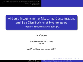
NASADC-8, AIRBORNE LABORATORYEXPERIMENTER HANDBOOKFigure 1-1(a). General view and over-all dimensions of the DC-8.Chapter 1Page 2June 2002
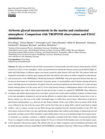
NASADC-8, AIRBORNE LABORATORYEXPERIMENTER HANDBOOKFigure 1-1(b). General view and over-all dimensions of the DC-8.Chapter 1Page 3June 2002
NASADC-8, AIRBORNE LABORATORYEXPERIMENTER HANDBOOKB.Runway LengthAt standard sea level conditions, the DC-8-72 typically requires a jettransport-rated runway of 7,500 ft (2,286 m), when take off weight is300,000 lb (136,079 kg). For a take-off weight of 325,000 lb(147,419 kg), the runway length must be at least 8,500 ft (2,591 m).With a maximum take-off weight of 350,000 lb (158,759 kg), therunway length must be 9,800 ft (2,987 m), minimum. The allowableaircraft take-off gross weight will be reduced by such limiting factorsas runway length, weight-bearing capability, slope, height above sealevel, as well as by air temperature, wind, and obstacles.C.Time at AltitudeThe time at a desired research altitude is dependent upon numerousfactors. The table below gives times for various take-off weights andtwo sample payloads, as representative of aircraft performance. Theone-hour allowance for time to climb and descend is an average,allowing variations in local air traffic control. The initial flight altitudewill be reached in about 30 min. If a higher altitude is desired, astep-climb can be achieved after aircraft weight has been reducedby fuel burn-off. Factors such as air temperature, aircraftconfiguration (probes, pylons, antennas, etc.), and air traffic controlwill determine when the aircraft can climb to a higher altitude.Traditionally, an individual flight plan
systems, and instruments have been installed in the aircraft to support a wide range of research programs. Airborne research missions for the DC-8 are planned, implemented, and managed by . research activities in the DC-8 airborne laboratory. This handbook is managed and revised from time to time by the DFRC Airborne Science Directorate .