Transcription
International Conference on Information Sciences, Machinery, Materials and Energy (ICISMME 2015)ARINC - 429 airborne communications transceiver system based onFPGA implementationLiu Hao1,Gu Cao2 ,MA Shi-guo3, Li Xin1 , He Gang1,41Naval Arm Academy, Shanghai, 2004362Air Force Command College, Beijing 1000893Unit 91445, Dalian Liaolin, 1160434Unit 91230, Fu’zhou Fujian,350000Keywords: ARINC-429 bus, FPGA, PC/104, airborne communications systemsAbstract. High performance integrated circuits are increasingly used in the aviation equipment.Airborne equipment to solve the data transmission, airborne equipment and the ARINC-429 bus isbased on PC/104 bus standard problem of communication between the microprocessor, and designsa scheme, using the FPGA's high-speed, flexibility to control the HI-8582 chip, to realize thereal-time receiving and sending of ARINC-429 bus, the control system adopts industrial computerPC104 transceiver channel, sending number, baud rate and other parameters, and real-time displayto send and receive information, realize the human-computer interaction. The FPGA control isapplied to save the hardware resources effectively, has fast processing speed, stronganti-interference ability, low cost, etc.IntroductionWith the ultra large scale integrated circuit technology leap development, integrated avionics,integrated more and more high. Data bus for fast, efficient equipment, reliable data transmission hasirreplaceable function. ARINC-429 bus is a joint Aeronautical Radio Incorporation set up by theAmerica aviation electronic equipment manufacturers, scheduled airlines, aircraft manufacturersand other national airline, developed by the company of a series of unified industry standards andspecifications of [1-2]. PC/104 embedded system with low power consumption, small volume, wideworking temperature range, high reliability and outstanding advantages of [3-5]. Earlyimplementation of ARINC-429 data transmission method generally uses the MCU control [6-8]system, but there exist low communication speed, timing control deficiencies is not flexible enough,not suitable for ARINC-429 high-speed communication.FPGA (Filed Programmable Gate Array, field programmable gate array) has the advantages ofhigh work frequency, the advantages of parallel processing data. The disadvantage of the traditionalmethods based on, this paper uses FPGA as the timing and decoding control chip, using 16 bit databus, the chip ARINC429, HI-8582 bus, so that the transmission rate of airborne communicationequipment to achieve high data rate 100kbit/s.The basic idea and frameworkAirborne communication system is mainly composed of the following three parts: thehuman-machine interactive part, data processing part, the underlying link transmission part ofairborne equipment. The three part between the relatively independent, each section independentlyto complete each function, data transmission through the corresponding interface, the system hasone one integral whole, work together to complete the data communication of airborne equipment.Work system, is divided into two processes: the process of sending data and receiving dataprocess. When sending data when the sender of information through the system, man-machinesystem will need to send the data information is sent to PC104, PC104 will convert the informationinto a data format in accordance with HI-8582 data form, and the address information and datainformation is also written to the FPGA internal memory, FPGA after receiving the message, using 2015. The authors - Published by Atlantis Press43
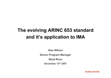
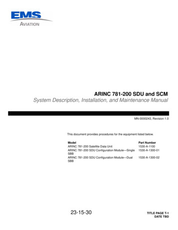
the first in first on the order of 32 bits of data are written in two chip HI-8582, in the FPGA controlunit for configuring HI-8582 to start the two receivers within HI-8582, sends out the data; when thesystem receiving the data, serial data from airborne equipment to transmit the flow inside the chipserial data are combined into 32 the bits of the data word, and stored in the internal FIFO, when theFIFO has data, the external pin data ready flag DR is set to a low level, at the same time interrupttrigger signal external microprocessor, the microprocessor to control HI-8582 chip correspondingsignal pin line, transmits the data to the FPGA internal memory, and then data transfer to PC104.Through the above two processes, the process of exchange system can orderly completion of PCand airborne equipment data.Composed of FPGA and HI-8582 of the ARINC-429 airborne communication system moduleUsing top-down design (Top-Down) in the forward design technical route [9-11], FPGA needs tocomplete the PC104 bus to read and write timing control, address decoding, data transmission andother functions, at the same time, also need to control receives two ARINC429 special chip and away to send, so that various data exchange orderly flow. Therefore, FPGA bus interface controllogic is mainly divided into two function modules: one is to control the PC104 bus to read and writethe logic, control the ARINC429 chip two is sending and receiving logic. This design adoptsXILINX company Spartan3A series devices of XC3S200A as the main control chip.PC104 read and write control module.This module is mainly used for PC104 bus data storageand read. The corresponding read-write control signal generated by FPGA, the width of the data busis 16 bits, address line width is 20 bits, memory address unit used in the internal distribution ofD0000-DFFFF, 64K storage. In the process of reading data, in order to make the datasynchronization and address sequence, using the same clock edge trigger, FPGA control logic willcache the data and address and sent to the PC104 bus; in the write data process, in the same clockedge trigger, data and address information at the same time into the FPGA internal cache. The readand write timing as shown in figure 1.CLKALEIOR/WData[15:0]Addr[19:0]AENIOCHRDFigure 1 PC/104 bus read and write timingARINC429 transmit / receive control module.ARINC429 bus communication specification isdesigned for the air transport industry standard between avionics transmission of digital informationand the development of the transport protocol, is a kind of point to point, bus consists of twodifferential signal circuit [12]. A total of 32 bit data words of bit ARINC429 specification, thecomposition of each data word is composed of 5 parts: the flag (Label the 1-8), the source / targetidentification code (SDI the 9-10), the data area (Data eleventh - 29), symbol / status bit (SSM the30-31), parity bit (Parity thirty-second). Consisting of 32 bit data words in the form of pulsethrough the STP serial transmission, and using the bipolar zero debug mode.The design used in the 429 communication chip HI-8582 for a 16 bit interface chip, the chip hastwo receivers and one transmitter, each receiver and transmitter has a 32 x 32 FIFO buffer, duringdata transmission, can register to detect the three FIFO via an external pin or state, when there isdata, interrupt processing data in the cache trigger external microprocessor. The HI-8582 chip tworeceivers and one transmitter can work independently, but share a 16 bit data path, in order to makethe two receivers and one transmitter HI-8582 coordinate work orderly, finite state machine is44
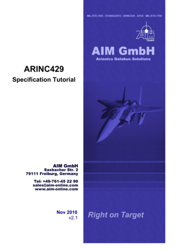
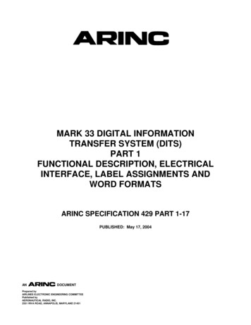
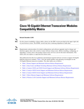
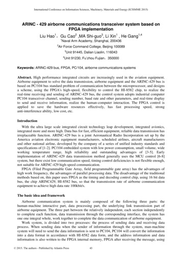
adopted in the design of [3-5] (Finite State Machine, FSM) design method, FPGA devices byXC3S200A chip control work.A state machine consists of,,, and a total of five states, respectively, said wait state, the sendingstate, the receiver 1 working state, the receiver 2 working state and all kinds of position signal clearstatus. After system reset enter wait state, on each rising edge of the clock arrived, send interfacelogic module to query the HI-8582 pin of the sign bit, data ready flag and the half full flag, whenthe effective, then enter the job ready state, according to the sign bit, into the corresponding sending/ receiving state, when the data transmission / receive after the treatment, then enter the state, theposition signal restoration, the address, data and enable signal reset. Fig. 2 Schematic shown inFigure state transition:rst 1rst 0S0S1/DR1 0TX/R 1S4S2/DR1 0TX/R 0TX/R 0S3/DR2 0/DR2 0Figure 2 state transition diagraminterrupt processing.Take appropriate interrupt processing mode and strategies have an importantrole to complete the reliable transmission of [13] 429 data. Because of the communication system,in addition to receiving 429 microprocessor system bus data process, also need to process the videosignal another expansion board, and interrupt priority video signals must be high, therefore themicroprocessor in the interrupt subroutine process 429 bus, may at any time may be video signalinterrupt subroutine interrupt execution process 429, will cause the interruption of bus datatransmission.Since microprocessor response is positive edge triggered interrupt mode, the interrupt signal andthe 429 special chip for signal generated from the 8582 level, namely the cache data, data readysignal is set to a low level, has been maintained until the cache is empty post is high, therefore, thedirect application of the data signal as interrupt sources, when PC interrupt response subroutinevideo signal is high priority interrupt subroutine interrupt, when the processor is idle, not again inresponse to the 429 bus generated interrupt response signal, so the design of the scheme is thatwhen the 429 bus data processing required, in each interrupt source signals effectively in theprocess of generating a pulse signal from inside FPGA and by the pulse trigger processor interruptresponse subroutine, so that the processor can effectively at the same time for processing the videosignal and the 429 data bus.Simulation testThe system uses ModelSim6.5b simulation tool to verify the FPGA design. The overall design ofthe structure of FPGA kernel, mainly includes the following modules:1) PC/104 bus decoding module: FPGA received from the host computer through the PC/104 busto instruction, and decodes them, generates corresponding control command, coordination of eachmodule at the same time, to make it orderly work;2) the data send / receive control module: mainly used to control the ARINC429 chip to read andwrite operations, data transmission is responsible for the completion of the underlying link. Thisdesign adopts the design method of finite state machine, the HI-8582 two receivers and one45
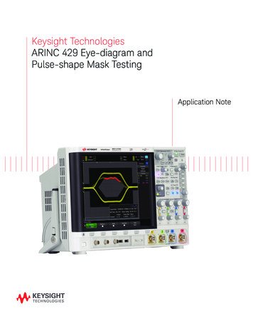
transmitter shared a 16 bit channel orderly completion of data transmission / reception work, itsstate transition simulation figure 3 as shown in fig.;Figure 3 finite state machine state transition simulation map3) interrupt processing control module: for external interrupt trigger microprocessor, interruptprocessing simulation as shown in figure 4. Because the HI-8582 given the data ready flag to levelsignal effective signal and micro processing the response to the rising edge triggered, so need todeal with;Figure4 interrupt processing simulationConclusionIn this paper, from the design requirements of airborne products are stable and reliable, highdegree of integration of the starting, and adopt XILINX company Spartan3A series FPGA devices,XC3S200A combines the high performance ARINC429 chip HI-8582, and with the periphery of thelevel conversion circuit, the design and implementation of ARINC429 interface module based onPC/104, this module supports various ways of working, less components, high reliability. At present,the entire ARINC429 airborne communication system has been applied to one type of machine, theactual work in the use of that, the design of the working performance of the communication systemis stable, the reliability is good.References[1] Sun Bo, Liu Baoming. The application and implementation of [J]. electronic technology designof SoPC intelligent communication module based on bus 429. 2012 (09): 11-14.[2] Wang Weifeng, Miao Kejian. Low altitude test instrument control program design andimplementation of PC104 based on [J]. electronic design engineering. 2012 (23): 12:15.[3] Xu Fangping, Yang Tongsheng. The monolithic design of [J]. computer and HS3282 networkbased on ARINC429 bus. 2012 (23): 31:33.[4] Li Dan, Liu Yuxiang, Fang Changzheng, Liu Quan. PC104 bus in the brake control unit on theapplication of [J]. electric locomotive and city rail vehicles. 2011 (01): 25-28.[5] Zhao Delin, Wang Shewei, Tao Jun, Yang Shangjun. Design of [J]. measuring technology ofARINC429 air interface card based on PC104 bus. 2011 (01): 27-31.[6] Liu Yue, Xing Shen. DSP multi functional PC104 bus serial communication card based on [J].application design technology. 2010 (02): 15-18.46
[7] Chen Dong, Han Zhizhong, Liang Yong. The ARINC429 bus interface design of [J]. industrialinstrumentation and automation device based on SOPC. 2010 (01): 17-20.[8] left season, Song Ying, and Liu Yu. Based on the PC104 (Plus) bus data receiving and storingdisplay system design of [J]. electronic components application. 2010 (11): 23-25[9] Wei Zenghui, a Xiaohui. Design of ARINC429 communication protocol implementation ofFPGA [J]. based on modern electronic technology. 2011 (05): 52-55.[10] Zhang Huaqiang, Zhao Yan, Chen rain and Realization of [J]. communication technology inthe design of ARINC429 communication system based on FPGA. 2010 (12): 15-19.[11] Liu Liansheng, Jiang Jianfei FPGA of ARINC429 chip design based on multi channel [J].microelectronics. 2010 (01): 30-33.[12] Jiang Xuedong, Liu Yong. Realization of ARINC429 interface and bus receiver [J]. modernelectronic technique using FPGA. 2010 (06): 41-44.[13] Chen Yu, Zhang Yanduo, Wang Chunmei. The 429 bus aircraft test instrument developmentand design [J]. Journal of Wuhan Institute of Technology based on the. 2011 (04): 45-48.47
ARINC-429 bus, FPGA, PC/104, airborne communications systems . Abstract. High performance integrated circuits are increasingly used in the aviation equipment. Airborne equipment to solve the data transmission, airborne equipment and the ARINC-429 bus is based on PC/104 bus standard problem of communication between the microprocessor, and designs