Transcription
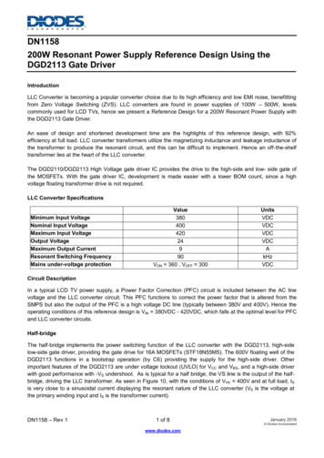
DN1158200W Resonant Power Supply Reference Design Using theDGD2113 Gate DriverIntroductionLLC Converter is becoming a popular converter choice due to its high efficiency and low EMI noise, benefittingfrom Zero Voltage Switching (ZVS). LLC converters are found in power supplies of 100W – 500W, levelscommonly used for LCD TVs, hence we present a Reference Design for a 200W Resonant Power Supply withthe DGD2113 Gate Driver.An ease of design and shortened development time are the highlights of this reference design, with 92%efficiency at full load. LLC converter transformers utilize the magnetizing inductance and leakage inductance ofthe transformer to produce the resonant circuit, and this can be difficult to implement. Hence an off-the-shelftransformer lies at the heart of the LLC converter.The DGD2110/DGD2113 High Voltage gate driver IC provides the drive to the high-side and low- side gate ofthe MOSFETs. With the gate driver IC, development is made easier with a lower BOM count, since a highvoltage floating transformer drive is not required.LLC Converter SpecificationsMinimum Input VoltageNominal Input VoltageMaximum Input VoltageOutput VoltageMaximum Output CurrentResonant Switching FrequencyMains under-voltage protectionValue38040042024990VON 360 , VOFF 300UnitsVDCVDCVDCVDCAkHzVDCCircuit DescriptionIn a typical LCD TV power supply, a Power Factor Correction (PFC) circuit is included between the AC linevoltage and the LLC converter circuit. This PFC functions to correct the power factor that is altered from theSMPS but also the output of the PFC is a high voltage DC line (typically between 380V and 400V). Hence theoperating conditions of this reference design is VIN 380VDC - 420VDC, which falls at the optimal level for PFCand LLC converter circuits.Half-bridgeThe half-bridge implements the power switching function of the LLC converter with the DGD2113, high-sidelow-side gate driver, providing the gate drive for 16A MOSFETs (STF18N55M5). The 600V floating well of theDGD2113 functions in a bootstrap operation (by C6) providing the supply for the high-side driver. Otherimportant features of the DGD2113 are under voltage lockout (UVLO) for VCC and VBS, and a high-side driverwith good performance with -VS undershoot. As is typical for a half bridge, the VS line is the output of the halfbridge, driving the LLC transformer. As seen in Figure 10, with the conditions of VHV 400V and at full load, ISis very close to a sinusoidal current displaying the resonant nature of the LLC converter (VS is the voltage atthe primary winding input and IS is the transformer current).DN1158 – Rev 11 of 8www.diodes.comJanuary 2016 Diodes Incorporated
DN1158Figure 1: Schematic of the 200W resonant power supply using the DGD2113 gate driverTransformer and secondaryLLC resonant transformers can be particularly difficult to design and implement with accuracy because themagnetizing inductance and leakage inductance of the transformer are the inductance of the LLC circuit itself.For short development time, ease of design, and high performance, the Magnetica 1860.0113 resonant switchmode transformer was used. These transformers have reinforced insulation and provide a high power/volumeratio. Magnetica is RoHS and ISO9001 qualified. Schottky rectifier diodes are used in the secondary to minimizepower dissipation and a secondary filter is used to decrease output noise. The transformer has a 300Wcapability, and the 16A MOSFETs can take the extra current, so if increased power capability is necessary,higher current secondary diodes and a higher current secondary inductor would need to be chosen.Feedback and controlThe feedback is based off the industry standard TL431 regulator using an opto-isolator. This configuration waschosen as suggested by the controller manufacture to match the resonant controller, the ICE1HS01G-1. Thisresonant controller converts feedback voltage to input signals to the DGD2113. But in contrast to a typical PWMcontroller, the ICE1HS01G-1 varies frequency of the control signals and maintains duty cycle (to near 50%, witha built in dead time). Other features of this controller, and hence the whole power supply, is over currentprotection, over load protection, and mains under voltage protection. A typical gain response of an LLCconverter can be seen in Figure 2. If operating at 100kHz, for example, and the input voltage is decreased, thecontroller will decrease the frequency of the control input. This can be seen in figure 8, operating at full load, butwith an input voltage of 380V, and an operating frequency of 80kHz. At nominal input voltage (400V) and fullload, the operating frequency is 90kHz, which is decided by the resonant capacitor (C15) and inherent leakageJanuary 2016DN1158 – Rev 12 of 8 Diodes Incorporatedwww.diodes.com
DN1158and magnetizing inductance of the transformer. For optimal performance of the Magnetica transformer, theresonant capacitor C15 must be a polypropylene film capacitor.Figure 2: Gain response of typical LLC converterFigure 3: Photograph of the Resonant Power Supply board LayoutDN1158 – Rev 13 of 8www.diodes.comJanuary 2016 Diodes Incorporated
DN1158Figure 4: Layout (top layer) of the Resonant Power Supply boardFigure 5: Layout (bottom layer) of the Resonant Power Supply boardPerformanceThe graphs and scope shots below show the performance of the Resonant Power Supply Reference Design.Figure 6 is a graph showing the efficiency vs. output power. As is typical of LLC converters, efficiency of 90%is easily achieved and for this design, efficiencies of 90% is achieved for loads of 70W to 200W, with anefficiency of 92% at full load. As can be seen in Figure 7, regulation is very tight over full load with less than0.2% change over the full load conditions. Efficiency and regulation over line voltage is not shown becausethere is negligible change in either efficiency or regulation over the varied line voltage of 380VDC to 420VDC.DN1158 – Rev 14 of 8www.diodes.comJanuary 2016 Diodes Incorporated
DN1158Figure 6: Efficiency vs. output power (VIN 400V)Figure 7: Regulation vs. output power (VIN 400V)Operation at Full and Low loadFigures 8 – 13 shows the operation of the power supply by monitoring the VS and IS while varying load andinput voltage (VIN). In the optimal operating point, you would expect the transformer primary current (IS) tobe sinusoidal. Hence figure 10 shows the LLC converter’s optimal operating point of Vin 400V, for aresonant frequency of about 90kHz. Also LLC converters work less efficiently at lower loads where they areunable to maintain ZCS and ZVS. Figures 9, 11, and 13 show the significant difference in shape of ISshowing the lack of soft switching. And lastly, looking at the three full load pictures (Figure 8, 10, and 12), yousee a frequency of operation of 80kHz for Vin 380V and increasing frequency as input voltage is increased.This follows the expected gain response for this type of converter; as you decrease voltage; more gain isneeded to maintain the same output voltage so the controller lowers the switching frequency as the LLCconverter gain response is higher at lower frequencies (see Figure 8). The LLC converter power supplyprovides high efficiency over wide load, but the input voltage is limited.Conditions for Figures below: Vout 24V, Full Load at 220W, Low Load 2.3WFigure 8: Operation at full load, VIN 380V,(VS green and IS purple)DN1158 – Rev 1Figure 9: Operation at low load, VIN 380V,(VS green and IS purple)5 of 8www.diodes.comJanuary 2016 Diodes Incorporated
DN1158Figure 10: Operation at full load, VIN 400VFigure 11: Operation at low load, VIN 400VFigure 12: Operation at full load, VIN 420VFigure 13: Operation at low load, VIN 420VDN1158 – Rev 16 of 8www.diodes.comJanuary 2016 Diodes Incorporated
DN1158Turn on at Full and Low LoadFigure 14: Turn on at full load, VIN 400VFigure 15: Turn on at low load, VIN 400VNo Load Power lusionA 200W Resonant Power Supply Reference Design with the DGD2113 High-Side, Low-Side Gate Driver wasdiscussed and the evaluation data was presented. This reference design is suited for LCD TV applications,provides greater than 90% efficiency and very tight regulation over wide loads and is highlighted because of itsease of design and short development time.DN1158 – Rev 17 of 8www.diodes.comJanuary 2016 Diodes Incorporated
DN1158IMPORTANT NOTICEDIODES INCORPORATED MAKES NO WARRANTY OF ANY KIND, EXPRESS OR IMPLIED, WITH REGARDS TO THIS DOCUMENT,INCLUDING, BUT NOT LIMITED TO, THE IMPLIED WARRANTIES OF MERCHANTABILITY AND FITNESS FOR A PARTICULARPURPOSE (AND THEIR EQUIVALENTS UNDER THE LAWS OF ANY JURISDICTION).Diodes Incorporated and its subsidiaries reserve the right to make modifications, enhancements, improvements, corrections or otherchanges without further notice to this document and any product described herein. Diodes Incorporated does not assume any liabilityarising out of the application or use of this document or any product described herein; neither does Diodes Incorporated convey any licenseunder its patent or trademark rights, nor the rights of others. Any Customer or user of this document or products described herein in suchapplications shall assume all risks of such use and will agree to hold Diodes Incorporated and all the companies whose products arerepresented on Diodes Incorporated website, harmless against all damages.Diodes Incorporated does not warrant or accept any liability whatsoever in respect of any products purchased through unauthorized saleschannel.Should Customers purchase or use Diodes Incorporated products for any unintended or unauthorized application, Customers shallindemnify and hold Diodes Incorporated and its representatives harmless against all claims, damages, expenses, and attorney fees arisingout of, directly or indirectly, any claim of personal injury or death associated with such unintended or unauthorized application.Products described herein may be covered by one or more United States, international or foreign patents pending. Product names andmarkings noted herein may also be covered by one or more United States, international or foreign trademarks.This document is written in English but may be translated into multiple languages for reference. Only the English version of this documentis the final and determinative format released by Diodes Incorporated.LIFE SUPPORTDiodes Incorporated products are specifically not authorized for use as critical components in life support devices or systems without theexpress written approval of the Chief Executive Officer of Diodes Incorporated. As used herein:A. Life support devices or systems are devices or systems which:1. are intended to implant into the body, or2. support or sustain life and whose failure to perform when properly used in accordance with instructions for use provided in thelabeling can be reasonably expected to result in significant injury to the user.B. A critical component is any component in a life support device or system whose failure to perform can be reasonably expected to causethefailure of the life support device or to affect its safety or effectiveness.Customers represent that they have all necessary expertise in the safety and regulatory ramifications of their life support devices orsystems, and acknowledge and agree that they are solely responsible for all legal, regulatory and safety-related requirements concerningtheir products and any use of Diodes Incorporated products in such safety-critical, life support devices or systems, notwithstanding anydevices- or systems-related information or support that may be provided by Diodes Incorporated. Further, Customers must fully indemnifyDiodes Incorporated and its representatives against any damages arising out of the use of Diodes Incorporated products in such safetycritical, life support devices or systems.Copyright 2016, Diodes Incorporatedwww.diodes.comDN1158 – Rev 18 of 8www.diodes.comJanuary 2016 Diodes Incorporated
In a typical LCD TV power supply, a Power Factor Correction (PFC) circuit is included between the AC line voltage and the LLC converter circuit. This PFC functions to correct the power factor that is altered from the SMPS but also the output of the PFC is a high vol