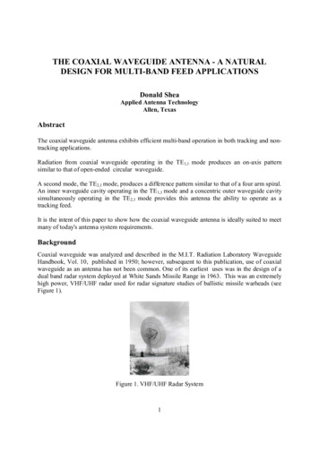
Transcription
Architectural &EngineeringSpecification forOmniTrax ranging buriedported coaxial cable outdoorintrusion detection systemPurpose of documentThis document provides performance and functional specifications for theOmniTrax intrusion detection system. It is written in a generic format withoutreferring to the OmniTrax system by name or by specific identifiers. Thesespecifications may be copied verbatim to form a generic procurementspecification for a ranging buried, ported, coaxial cable intrusion detectionsystem.Classification of equipmentOmniTrax is a ranging buried ported coaxial cable electromagnetic field sensorsystem for outdoor perimeter intrusion detection. OmniTrax functions as astandalone system or as an integral component of a centralized control andmaintenance facility.DisclaimerOmniTrax and Senstar are registered trademarks and the Senstar logo is atrademark of Senstar Corporation. The information in this document is subject tochange without notice. Senstar reserves the right to make changes to productdesign or manufacturing methods, as engineering progresses, or as othercircumstances warrant.A4DA0115-001, Rev. Dpage 1May, 2011
Architectural & Engineering Specificationfor a ranging buried ported coaxial cableoutdoor intrusion detection systemContentsMay, 20111.0General performance specifications.32.0Processor specifications .83.0Centralized control & maintenance . 144.0System installation and commissioning . 155.0System maintenance and repair. 156.0Product certifications . 157.0System availability . 16page 2A4DA0115-001, Rev. D
Architectural & Engineering Specificationfor a ranging buried ported coaxial cableoutdoor intrusion detection system1.0General performance specifications1.1System descriptionThe system shall be a modular ranging buried coaxial cable outdoor intrusiondetection sensor system based on ported coaxial cable technology. The detectionfield shall be formed by radio-frequency (RF) signals carried by sensor cablesthat are buried along the perimeter. The RF signals shall form an invisibleelectromagnetic detection field around the sensor cables that can locate anddetect an intruder passing through the field.A processor shall contain the electronics required to: Transmit and receive the RF signal without the use of an external antenna Monitor the detection fields of up to 2 sensor cable sets Determine the position of intruders to within /- 1 meter with a 95%confidence factor Provide uniform detection performance along the length of the sensor cablesregardless of the burial medium by using a unique detection threshold foreach meter of cable Raise an alarm when an intruder enters the monitored zones Communicate alarm, status, and configuration information over a datanetwork via an optional communications interface card Communicate alarm and status information via relay contactsField power modules shall be available for standalone systems and networksystems. Standalone power modules shall supply 12 VDC power for oneprocessor. Network power modules shall supply 48 VDC power for up to fiveprocessors. It shall be possible to supply power to each processor through thesensor cables.All processors shall provide the ability to adjust parameters using a laptop PCconnected directly to the processor via a Universal Serial Bus (USB) cable.The data network supported by the system shall communicate through a centralnetwork interface unit that provides standard communications interfaces forconnection to computer equipment. Via the network interface unit and associatednetwork management software, the system shall provide all the alarm and statusinformation needed to implement the operator interface. In addition,configuration software shall be available so that all system calibration andadjustments can be done over the data network from a central location.1.2System technology1.2.1Ported coaxial cableThe system shall use ported (leaky) coaxial cables as the sensing elements. Thesize of the port (opening) shall change with cable length to optimize the strengthof the receive signal. A detection field shall be created using pulse-coded RFsignals that are generated by the processor and carried by the coaxial cables.Each system requires a transmit cable to transmit the RF signal, and a receiveA4DA0115-001, Rev. Dpage 3May, 2011
Architectural & Engineering Specificationfor a ranging buried ported coaxial cableoutdoor intrusion detection systemcable to receive the signal and carry it back to the processor. Transmission andreception shall be accomplished without the use of antennae. The RF signalreceived on the receive cable shall be monitored and analyzed for any changesthat would indicate the presence of an intruder. The system shall be available intwo configurations that are suitable for different applications: a two-cable sensor system that includes separate transmit and receive cables,for installation in either one trench or two parallel trenches up to 400 m(1312 ft.) per processor; 200 m (656 ft.) per cable a two-cable sensor system that includes separate transmit and receive cables,for installation in either one trench or two parallel trenches up to 800 m(2624 ft.) per processor; 400 m (1312 ft.) per cableIn all cases, the cable shall be capable of being used for power distribution (topower multiple processors from a single source) and for distribution andcollection of alarm and other diagnostic information.1.2.2Sensor cable systemThe sensor cable system shall use two separate cable assemblies, each consistingof a single ported coaxial cable in its own jacket. The outer jacket shall be madeof abrasion and chemical resistant, high-density polyethylene. The cableassembly shall include a flooding compound to prevent the ingress of water if theouter jacket is nicked.1.2.3Electromagnetic fieldDetection shall rely on an electromagnetic field that is formed completely aroundthe buried sensor cables.1.2.4Sensor cable burial depthThe standard burial depth of the sensor cables shall be 23 cm (9 in.) in soil and6 cm (2.5 in.) in hard surfaces such as asphalt or concrete.1.2.4Sensor cable separationIt shall be possible to install the sensor cables with any cable separation from 10cm (4 in.) to 2 m (79 in.)1.3Detection properties1.3.1Detection sensitivityThe system shall detect moving intruders that have a significant electromagneticcross-section (e.g., humans, vehicles, and other large conductive objects) whilerejecting other environmental stimuli (e.g., birds, small animals, weather).May, 2011page 4A4DA0115-001, Rev. D
Architectural & Engineering Specificationfor a ranging buried ported coaxial cableoutdoor intrusion detection system1.3.2Detection performance1.3.2.1 Probability of detectionThe probability of detecting a human intruder walking across the protectedperimeter at random locations shall be 99% with a 95% confidence factor.1.3.2.2 Intruder locationThe system shall determine and display the location of intruders. For intruderscrossing the sensor cable at any given location the declared position shall berepeatable within /-1 meter with a 95% confidence. It is noted that thedetermination of absolute location along the cable can vary with installationconditions.1.3.2.3 Velocity responseThe system shall be capable of detecting upright human intruders movingthrough the detection field at speeds between 5 cm/s (2 in./s) and 8 m/s(26 ft./s) regardless of the direction of motion. The velocity response settingshall be programmable to optimize detection at low speed while reducing sitenuisance alarms.1.3.2.4 Intruder weightThe system shall detect human intruders weighing more than 35 kg (77 lb) at thespecified probability of detection (PD) (section 1.3.2.1).1.3.2.5 Crossing typesThe system shall detect human intruders who walk, crawl, roll, jump, or runthrough the detection field.1.3.3False alarms1.3.3.1 System-generated alarmsAlarms generated by internal electronic processes (cables excluded) shall notexceed one per zone per month. System generated alarms are averaged based onthe total number of zones in the system.1.3.3.2 Small animal alarm rejectionThe probability of detecting a small animal, weighing less than 10 kg (22 lb),crossing the perimeter shall be less than 5% with a confidence factor greater than90%.1.3.3.3 Environmental alarmsWhen installed in accordance with the manufacturer's recommendations, thesystem shall operate within specifications in typical outdoor environments.A4DA0115-001, Rev. Dpage 5May, 2011
Architectural & Engineering Specificationfor a ranging buried ported coaxial cableoutdoor intrusion detection systemSpecifically, the system shall maintain the full probability of detection for validintruders while minimizing false alarms from the following stimuli: Vegetation up to 30 cm (1 ft.) high Rain Sunrise/sunset Wind Temperature changes Snow Hail Fog Sandstorms Seismic vibration Acoustic or magnetic effectsThe supplier shall provide site planning information to enable site conditions(i.e., site grade, standing water, nearby objects) to be optimized for minimalnuisance alarms.1.4Sensor characteristics1.4.1Cable lengthThe system shall provide detection coverage to a maximum distance of 400 m(1312 ft.) per cable set. Sensor cables shall be available in standard lengths of50 m (164 ft.), 100 m (328 ft.), 150 m (492 ft.), 200 m (656 ft.), 300 m (984 ft.),and 400 m (1312 ft.). Each sensor cable shall include a minimum of 4 m ofdetecting cable, in addition to the specified length, in which the detection fieldcan build up to full strength.1.4.2Sensor segments and zonesIt shall be possible to divide the perimeter protected by the sensor cable intomultiple segments and zones. The supplier shall provide a software tool that runson a Windows PC for the creation of segments and zones.1.4.2.1 Software functional segmentationIt shall be possible to create in software multiple functional segments in eachsensor cable set. The segments can be declared as active or inactive, and can beset to unique detection parameters. It shall be possible to set up to 50 functionalsegments per sensor cable set. A segment shall have a minimum length of 1 m(3.3 ft.) and a maximum length of the combined length of the two sensor cablesets connected to one processor.May, 2011page 6A4DA0115-001, Rev. D
Architectural & Engineering Specificationfor a ranging buried ported coaxial cableoutdoor intrusion detection system1.4.2.2 Software zoningIt shall be possible to combine one or more software functional segments intoalarm reporting zones for operator control. It shall be possible to set up areporting zone that bridges over the two sensor cables at their point of overlap. Itshall be possible to set up to 50 alarm reporting zones per sensor processor.1.4.3Detection field dimensionsWhen the system is calibrated in accordance with the manufacturers’recommendations: The detection field shall be continuous and uniform over the protected siteperimeter, excluding segments that are set to be inactive. The typical cross-section of the detection field shall meet the followingdimensions: Height – 1 m (3.3 ft.) above ground Width –up to 3 m (9.8 ft.), depending on cable separation Depth – 0.5 m (1.5 ft.) below ground1.4.4Terrain-following characteristicsThe detection field shall not be limited to flat terrain or line-of-sight operation.The system shall operate within specifications over uneven terrain with amaximum grade change of 30º within 4 m (13 ft.) and around corners with aminimum turn radius of 7.0 m (23 ft.).1.4.5Range of containmentWhen system sensitivity is calibrated according to the manufacturer’srecommendations, the detection field shall not detect a human intruder that is2 m (6.5 ft.) or more away from the nearest sensor cable.1.4.6Operation in frozen soilThe freezing of the burial medium during cold weather operation shall not causedegradation in the performance of the system or damage to the system’scomponents. The only adjustment required after freezing or thawing isrecalibration of thresholds.1.4.7Operation in areas of high moisture contentThe sensor cables and underground connections shall be impervious to wateringress and degradation for a minimum of 10 years. The system shall operatewithin specifications in soil saturated with fresh water.A4DA0115-001, Rev. Dpage 7May, 2011
Architectural & Engineering Specificationfor a ranging buried ported coaxial cableoutdoor intrusion detection system1.4.8Burial-mediumsThe system shall operate within specifications when installed in burial mediumswith conductivity ranging from 10 mS/m to 200 mS/m, including, but not limitedto, sand, clay, soil, asphalt and concrete.1.4.9Snow coverThe sensor system shall operate within specifications when covered by snow upto 30 cm (1 ft.) deep.2.0Processor specifications2.1Processor descriptionEach processor shall contain the electronics required to handle the signalprocessing for 100 software-defined functional segments on two sets of sensorcables, including the calculations necessary to determine the location ofintruders. The processor shall operate in either a standalone configuration, or ina network configuration. The processor shall be provided in a weatherproofenclosure providing the protection level of CSA Type 4 (equivalent toNEMA 4).2.2Processor operation2.2.1Distributed processingEach processor shall transmit, receive and process the electromagnetic detectionfields for two cable sets, independently from other processors. Each processorshall provide coverage for up to 800 m (2,624 ft.) of perimeter.2.2.2Adaptive filterThe processor shall use an adaptive filter that adjusts the signal processing toreduce nuisance alarms caused by environmental factors such as rainfall or slowrunning water.2.2.3Total perimeter lengthThe total perimeter shall be expandable to an unlimited length by using multipleprocessors. There shall be no gap in the detection field between the individualzones or cables.The system shall be able to protect a continuous perimeter of up to 4.0 km(2.49 miles) while having power supplied at only one processor location.The integrated data network shall provide data networking capability forperimeters of up to 48 km (29.8 miles) while requiring that the network interfaceunit be attached to the network at only one processor location. To providecommunications redundancy it shall be possible to attach the network interfaceunit to the data network at two different proce3ssors.May, 2011page 8A4DA0115-001, Rev. D
Architectural & Engineering Specificationfor a ranging buried ported coaxial cableoutdoor intrusion detection system2.2.4Alarm outputsIn standalone mode, the processor shall output alarms to four on-board Form Crelays, (Alarm A, Alarm B, Supervision, Fail). The relays shall be rated at 1.0 Aat 30 VAC/VDC.In network mode, the buried sensor cables shall support a data network thatcommunicates sensor alarms, supervision alarms, fail alarms, and status andconfiguration information. The network interface unit shall be able to connect tothe data network at processors equipped with a communications interfacemodule. To provide network redundancy it shall be possible to connect thenetwork interface unit to the data network at two different processors. Thefollowing options shall be available for the physical media between the networkinterface unit and the processor(s) where the network attachment is made:EIA-422, dual multimode fiber, dual singlemode fiber.2.2.4.1 Sensor alarmIn standalone mode, intrusion into any zones that are supervised by the processorshall be identified by a contact closure, Alarm A for cable set A, and Alarm Bfor cable set B. With the addition of a plug-in auxiliary relay output card to theprocessor, it shall be possible to output an intrusion alarm to one of 10 auxiliaryrelays (2 on processor 8 on auxiliary relay card). These auxiliary relays shall berated at 1.0 A at 30 VAC/VDC.In network mode, intrusion into any zones that are supervised by a processorshall be identified by alarm type (sensor) and location (zone ID) and distance inmeters from a calibrated reference point. This information shall be transmittedover the data network and made available via the network interface unit to thesecurity management system.2.2.4.2 Supervision alarmA Supervision alarm caused by opening the processor enclosure or cable faultshall be identified by alarm type (Supervision) and location (Processor ID). ASupervision alarm shall not reset until the cause of the alarm is corrected.2.2.4.3 Fail alarmA Fail alarm caused by power failure or internal electronic fault shall beidentified by alarm type (Fail) and location (Processor). A Fail alarm shall not bereset until the cause of the alarm is corrected.2.2.4.4 Fail-safe relay operationBoth the Fail and Supervision relays shall operate in fail-safe mode, whereby therelays shall latch in the non-alarm state during normal operation. Upon the lossof the DC power input the Fail relay shall change to the alarm state to indicatethe power failure. Upon the loss of DC power and the loss of battery back-uppower the Supervision relay shall change to the alarm state to indicate acomplete loss of power.A4DA0115-001, Rev. Dpage 9May, 2011
Architectural & Engineering Specificationfor a ranging buried ported coaxial cableoutdoor intrusion detection system2.2.4.5 Self-testThe processor shall be capable of performing a diagnostic self-test of eithersensor cable set by either local or remote activation. The self-test feature shallcause an internal electronic test of the processor.2.3Optional transponder modulesIn network mode, the base processor, without the aid of any auxiliary cards, shallhave available two supervised input points to capture the alarm data fromauxiliary sensors and four output relays for the control of auxiliary equipment.The four relay outputs shall be rated at 1.0 A at 30 VAC/VDC, non-inductiveload.Further, in network mode, the processor shall be able to accept one optionalplug-in transponder module to expand the input or output capacity.2.3.1Optional 8-input transponder moduleThe optional 8-input transponder module shall provide eight supervised inputswhile allowing normal operation of the two supervised inputs and four relayoutputs that are integral to the processor.2.3.2Optional relay output moduleThe optional relay output module shall provide eight Form C dry contact relayoutputs, rated at 1.0 A at 30 VAC/VDC. This module shall allow normaloperation of the two supervised inputs and four relay outputs that are integral tothe processor.2.4Optional communications modulesIt shall be possible to equip the processors with communications modules toenable them to support data networking. Communications modules shall beavailable in five configurations: EIA-422/EIA-422, Multimode FiberOptic/Multimode Fiber Optic, Singlemode Fiber Optic/Singlemode fiber Optic,EIA-422/Multimode Fiber Optic and EIA-422/Singlemode Fiber Optic, A datacommunication interface card shall be mandatory for each processor usingnetwork communications including when data is networked over the cables.2.5Optional auxiliary power supply moduleAn auxiliary power supply shall be available for installation inside the processorenclosure. The auxiliary power supply shall convert 48 VDC supplied from thesensor cables to 12 VDC to power external devices. It shall be capable ofsupplying up to 150 mA at 12 VDC.May, 2011page 10A4DA0115-001, Rev. D
Architectural & Engineering Specificationfor a ranging buried ported coaxial cableoutdoor intrusion detection system2.6Environmental operating range2.6.1TemperatureThe processor shall operate within specifications at temperatures between–40º and 70º C (–40º and 158º F).2.6.2HumidityThe processor shall operate within specifications at humidity levels ranging from0 to 95% relative humidity, non-condensing.2.7Powering Requirements2.7.1Input powerProcessors shall function with input power in the range of 10 to 48 VDC.Maximum power consumption shall be 9W.2.7.2Network power capabilityThe network field power module shall be capable of supplying power to up toseven processors over the sensor cable.2.7.3Power cable redundancyIn a network configuration where power is supplied redundantly via the sensorcables, the processors shall operate within specifications when power is removedfrom either of the two sensor cables.2.7.4Backup batteryIt shall be possible to equip the processor with an optional internal backupbattery with a minimum capacity of 5Ah. In the event of loss of the prime inputpower the processor shall switch over automatically to the backup batterywithout any disruption in performance and annunciate the power loss either tothe local Fail relay or over the data network if so configured. The processor shallhave charging circuitry to maintain the battery at full charge when prime poweris available.2.8Reliability/maintainabilityThe processor shall have a calculated Mean Time Between Failure (MTBF) ofgreater than 40,000 hours. The Mean Time to Replace (MTTR) a processor shallbe less than 15 minutes.2.9Physical installation criteria2.9.1Processor enclosuresThe processor shall be provided in a weatherproof enclosure providing theprotection level of CSA Type 4 (equivalent to NEMA 4).A4DA0115-001, Rev. Dpage 11May, 2011
Architectural & Engineering Specificationfor a ranging buried ported coaxial cableoutdoor intrusion detection system2.9.2Covert installationThe processor enclosure shall be capable of covert installation within a telecomenclosure.2.9.3Location of processorA non-sensing section of cable shall be included as an integral part of the cableset to allow the processor to be located away from the detection field. Thestandard length of non-sensing cable shall be 20 m (66 ft.). The non-sensingcable shall not reduce the 400 m (1312 ft.) maximum length of the active cable.2.9.4Lead-in/sensing cable junctionThe junction between the non-sensing section of lead-in and the sensor cableshall be integral to the cable assembly and shall require no connectors or breaksin the outer jacket of the cable. The lead-in section of the sensor cable shall be20 m (66 ft.) in length and shall be adjustable by either cutting out or splicing inadditional sections of non-sensing cable.2.9.5Lightning protectionThe processor shall include internal components to protect circuitry from powersupply transients and lightning. Optional external protection devices shall beavailable for use in areas with a high incidence of lightning.2.10Sensor calibrationIt shall be possible to perform all calibration and configuration of the processorsusing supplier-furnished software running on a Windows PC. It shall bepossible to perform this locally at the processor with a direct USB connection orremotely via the data network.Access to the processor USB connection shall require removal of the enclosure’scover and shall cause a Supervision alarm to be generated.2.10.1Calibration walkIt shall be possible to calibrate the system by having a person walk along thelength of the protected perimeter, over the center of the detection zone. Duringthe calibration walk the processor shall be connected to a Windows PC runningthe configuration software. The configuration software shall measure and recordthe sensor cable response and set the threshold for each meter (3.3 ft) of thecable. The configuration software shall use the results of the calibration walk todetermine the appropriate setting for the processor’s transmitter power level.May, 2011page 12A4DA0115-001, Rev. D
Architectural & Engineering Specificationfor a ranging buried ported coaxial cableoutdoor intrusion detection system2.10.2Sensitivity adjustmentIt shall be possible to adjust detection sensitivity for each zone with a Windows PC. It shall be possible to perform this locally at the processor with a USBconnection or remotely via the data network.2.10.2.1 Local sensitivity measurementIt shall be possible to view and record the processor’s response on a Windows PC. It shall be possible to perform this locally at the processor with a USBconnection or remotely via the data network. The PC shall display the alarm trippoint, thereby showing the processor’s degree of detection above or below thelevel required to cause an alarm.2.10.2.2 Functional segmentationIt shall be possible to use a Windows PC to define up to 50 functional segmentsper sensor cable. A functional segment shall be subject to further sensitivityadjustments for optimum performance or it can be defined as non-reporting. Anon-reporting functional segment shall not report intrusion alarms that occurwithin its defined length.2.10.2.3 Reporting zonesIt shall be possible to use a Windows PC to combine one or more functionalsegments into alarm reporting zones. It shall be possible to define up to 50 alarmzones per processor.A4DA0115-001, Rev. Dpage 13May, 2011
Architectural & Engineering Specificationfor a ranging buried ported coaxial cableoutdoor intrusion detection system3.0Centralized control & maintenanceThe sensor shall provide an integrated data networking capability to allow it tobe integrated into a centralized control and maintenance facility.3.1 Network characteristicsThe data network shall be capable of communicating all alarm, status, andconfiguration information between the processors and a network interface unit.The data network shall use a loop topology with separate Transmit and Receivepoint-to-point links between processors, or between a processor and othercompatible equipment such as the network interface unit. The following physicalmedia options shall be available for the point-to-point links: EIA-422 singlemode or multimode fiber the sensor cablesIt shall be possible to link up to 60 processors together into one network.The data network shall communicate through a central network interface unitthat provides standard communications interfaces for connection to computerequipment. The standard interfaces available from the network interface unitshall be EIA-232, USB, and Ethernet. Via the network interface unit andassociated network management software the system shall provide all the alarmand status information needed to implement an operator interface. It shall bepossible to attach a network interface unit to one processor, or to two processors,to provide redundant data paths to the processor network.The supplier’s configuration software shall be capable of using the data networkso that all system calibration and adjustments can be done from a centrallocation.It shall be possible to have multiple networks, each with up to 32 processors,managed by multiple instances of the network interface unit and associatedsoftware, all reporting to one control and maintenance display system.3.2 Network management softwareThe supplier shall make available network management software that runs on aWindows PC to control the flow of information on the data network. Thenetwork management software shall control the network via the networkinterface unit and provide a software interface that gives access to all alarm,status, and configuration information. The software interface shall beimplemented via TCP/IP.The supplier shall make available complete documentation of the softwareinterface provided by the network manager software to enable integration withthird-party Security Management Systems.May, 2011page 14A4DA0115-001, Rev. D
Architectural & Engineering Specificationfor a ranging buried ported coaxial cableoutdoor intrusion detection system4.0System installation and commissioningThe supplier shall make available a complete documentation package to enablesuccessful site planning and design, installation, and commissioning of thesystem.The supplier shall make available a training course or courses to cover thefollowing: site planning and design system installation system commissioning system integration with Security Management Systems5.0System maintenance and repair5.1Recalibration requirementsThe system shall not require recalibration after initial calibration, with theexception of systems that are installed where seasonal changes cause freezingand thawing of the burial medium. These systems may require minor seasonalrecalibration to maintain ideal sensitivity levels.5.2Sensor cable repairIf the sensor cable is cut or damaged, it shall be capable of being repaired.5.3Product supportThe product shall be under warranty for a minimum of three years from the dateof purchase.The end-user shall have the option of extending the warranty to five yearswithout additional fees.The supplier shall provide technical support and shall warrant that spare partsand assemblies shall be available for a minimum of 10 years after installation.6.0Product certificationsThe system shall comply with FCC and IC regulations for the operation of aradio-frequency radiating device.The system shall comply with European CE regulations and carry the CE mark.The manufacturer’s quality management system shall have ISO 9001-2000certification.A4DA0115-001, Rev. Dpage 15May, 2011
Architectural & Engineering Specificationfor a ranging buried ported coaxial cableoutdoor intrusion detection systemThe product shall comply with safety standard IEC 60950-1:2001 and thesupplier shall make available upon request a CB Test Certificate confirming suchcompliance.7.0System availabilityA product that meets or exceeds this specification is the OmniTrax outdoorintrusion detection system, available from:Senstar Corporation119 John Cavanaugh DriveCarp, OntarioCanada K0A 1L0Telephone: 1-613839-5572Fax: 1613-839-5830Toll Free: 800 390-5796 – CanadaToll Free: 800 676-3300 – USwww.senstar.cominfo@senstar.comMay, 2011page 16A4DA0115-001, Rev. D
for a ranging buried ported coaxial cable outdoor intrusion detection system A4DA0115-001, Rev. D page 3 May, 2011 1.0 General performance specifications 1.1 System description The system shall be a modular ranging buried coaxial cable outdoor intrusion detection sensor system based on ported coaxial cable technology. The detection