Transcription
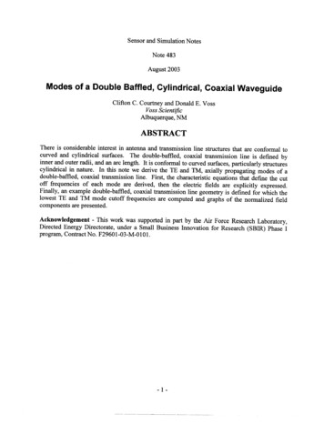
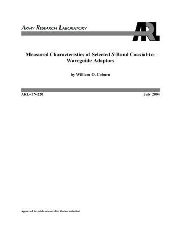
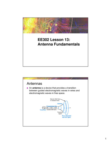
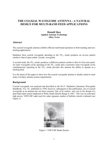
THE COAXIAL WAVEGUIDE ANTENNA - A NATURALDESIGN FOR MULTI-BAND FEED APPLICATIONSDonald SheaApplied Antenna TechnologyAllen, TexasAbstractThe coaxial waveguide antenna exhibits efficient multi-band operation in both tracking and nontracking applications.Radiation from coaxial waveguide operating in the TE 1,1 mode produces an on-axis patternsimilar to that of open-ended circular waveguide.A second mode, the TE2,1 mode, produces a difference pattern similar to that of a four arm spiral.An inner waveguide cavity operating in the TE 1,1 mode and a concentric outer waveguide cavitysimultaneously operating in the TE2,1 mode provides this antenna the ability to operate as atracking feed.It is the intent of this paper to show how the coaxial waveguide antenna is ideally suited to meetmany of today's antenna system requirements.BackgroundCoaxial waveguide was analyzed and described in the M.I.T. Radiation Laboratory WaveguideHandbook, Vol. 10, published in 1950; however, subsequent to this publication, use of coaxialwaveguide as an antenna has not been common. One of its earliest uses was in the design of adual band radar system deployed at White Sands Missile Range in 1963. This was an extremelyhigh power, VHF/UHF radar used for radar signature studies of ballistic missile warheads (seeFigure 1).Figure 1. VHF/UHF Radar System1
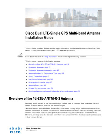
In 1967, coaxial waveguide operating in the TE1,1 and TE2,1 modes was shown to producepatterns required by a dual mode tracking feed. This concept was studied for use in anSCM(Single Channel Monopulse) tracking system and a dual band prototype (Figure 2) wasbuilt and tested .It was recognized that this new approach was far superior to the feed systems then being usedand showed that a parabolic reflector with a multi-band feed could perform the work of severalreflectors using single band feeds without sacrificing performance.Figure 2. LS Band SCM Tracking FeedA mobile tri-band SATCOM system, using a coaxial waveguide feed (Figure 3), was developedfor the Army on an SBIR contract in 1999. The design was voted the program's Best TechnicalInnovation for that year.Figure 3. Tri-band SATCOM AntennaAntennas of this type were subsequently manufactured and deployed in both commercial andmilitary SATCOM systems. Examples are shown below:Large Tri-band SATCOMGround StationTri-band ProgrammedTrack AntennaTransportable Tri-bandSATCOM Antenna2
A tri-band SCM tracking system (Figure 4) was recently developed and is operational at severaltracking sites. This antenna covers all designated telemetry frequency bands and provides theoperational capability of three separate single band systems.Figure 4. Tri-band Telemetry Tracking AntennaPrinciple of OperationThe field distribution of the TE1,1 mode in coaxial waveguide is shown in Figure 5.2a2bFigure 5. Electric Field Associated with TE1,1 Mode in Coaxial WaveguidePropagation can occur when the mean circumference is greater than one wavelength. The cutoffwavelength is therefore given by the formula: co (a b)An open-ended waveguide of this type radiating into space produces an on-axis (SUM) patternas shown in Figure 6. An orthogonal TE1,1 mode (see Figure 7) can be simultaneously excited inthe waveguide to produce either dual linear or dual circular polarization. A beamformer networkfor producing a dual circularly polarized SUM pattern is shown in Figure 8.3
Figure 6. TE1 1 Pattern Produced byOpen-ended Coaxial WaveguideFigure 7. Cross-polarized TE 1,1 Fieldsin Coaxial WaveguideLCP RCP Legend:90º Hybrid180º HybridFigure 8. Beamformer for Producing Dual Circular PolarizationThe field distribution of the TE2,1 mode in coaxial waveguide is shown in Figure 9.2a2a2b2bFigure 9. Electric Field Associated with TE2,1 Mode in Coaxial Waveguide4
Propagation can occur when the mean circumference is greater than two wavelengths. The cutoffwavelength for this mode is therefore given by the formula: co (a b)/2An open-ended waveguide of this type produces a null (DIFFERENCE) pattern as shown inFigure 10. A second TE2,1 mode, rotated 45º, as shown in Figure 11, can be simultaneouslyexcited in the waveguide to produce a dual circularly polarized DIFFERENCE pattern. An eightport beamformer to produce these modes is shown in Figure 12.Figure 10. Difference (mode TE2,1) PatternFigure 11. Dual TE 2,1 Modes excited in Coaxial WaveguideLCP RCP Legend:Power divider90º hybrid180º hybridFigure 12. TE2,1 Mode Beamformer5
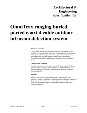
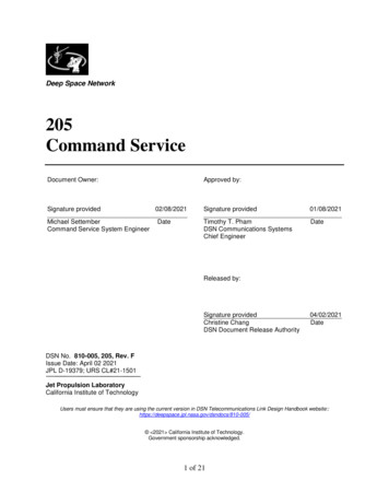
A Non-Tracking Multi-Band Feed Design ExampleThe following describes a dual circularly polarized coaxial waveguide feed which can operateover the following frequencies:L-Band: 1.000 to 1.750 GHzS-Band: 2.050 to 2.500 GHz andX-Band: 7.800 to 9.000 GHzThis design can be implemented with three concentric coaxial waveguide cavities arranged asshown in Figure 13.L-bandS-bandC-bandFigure 13. Waveguide Configuration for Tri-band Non-Tracking FeedThe two outer waveguide cavities are fed with four finline transitions as shown in Figure 14.Figure 14. Coaxial Waveguide to Coaxial Transmission Line TransitionsThese cavities operate in both left and right circular polarization using a four port beamformeras shown previously in Figure 8. The inner waveguide cavity is fed with an OEM septumpolarizer.HFSS (High Frequency Structure Simulator) software was used to design the feed shown inFigure 15.6
FrontBackFigure 15. Tri-Band Non-Tracking FeedComputed PerformanceVSWR2:1 VSWR2:1 VSWRL-Band2:1 VSWRS-Band2:1 VSWRPrimary PatternsL-BandX-BandS-Band7X-Band
An SCM/Monopulse Tracking Feed Design ExampleThe following describes a dual circularly polarized coaxial waveguide tracking feed which canoperate over the following frequencies:L-Band: 1.435 to 1.540 GHz and 1.755 to 1.850 GHzS-Band: 2.200 to 2.400 GHzC-Band: 4.400 to 5.150 GHzThis design is implemented with four concentric coaxial waveguide cavities arranged as shownin Figure 16.L-Band DIFFERENCEL-Band SUM / S-band DIFFERENCES-Band SUM / C-band DIFFERENCEC-Band SUMFigure 16. Waveguide Configuration for Tri-band Tracking FeedThe three outer waveguide cavities are fed with eight finline transitions as shown in Figure 17.Figure 17. Coaxial Waveguide to Coaxial Transmission Line TransitionsAs seen in Figure 16, two of the waveguide cavities operate simultaneously in both SUM andDIFFERENCE modes. They are fed using the beamformer shown in Figure 18.8
RCP LCP RCP LCP Legend:Power divider90º hybrid180º hybridFigure 18. Eight Port SUM/DIFFERENCE BeamformerThe central cavity (C-Band SUM) is fed with an OEM ortho-mode septum polarizer.HFSS (High Frequency Structure Simulator) software was used to design the feed shown inFigure 19.FrontBackFigure 19. Tri-Band Telemetry Tracking Feed9
Computed PerformanceVSWRS-BandL-BandC-BandPrimary PatternsL-BandS-BandC-BandConclusionThis paper describes how the coaxial waveguide antenna satisfies the requirements of bothnon-tracking and tracking feeds with near text book perfect results. Several designs of this typehave been fielded and the performance predicted by HFSS simulation has been repeatedlyconfirmed by testing.Other advantages of this type of feed is that it can operate in all bands simultaneously, it ispolarization diverse. and can generally be designed as a plug-and-play replacement for existingSCM and conical scan tracking feeds.10
This design can be implemented with three concentric coaxial waveguide cavities arranged as shown in Figure 13. Figure 13. Waveguide Configuration for Tri-band Non-Tracking Feed The two outer waveguide cavities are fed with four finline transitions as shown in Figure 14. Figure 14. Coaxial Waveguide to Coaxial Transmission Line Transitions