Transcription
Construction manualBroadband applications and construction manualDrop cable products
Contentscommscope.comIntroduction3Description of cable types5Cable selection guide6Planning the run12Aerial installation13Buried installation16Attaching to the ground block per NEC 83019Attaching to the NIU per NEC 83020Residential interior cabling22Multiple dwelling units (MDUs)28Commercial installations31Drop cable descriptions/specifications32Appendix33Broadband resource center362
How to use this guideThe drop cable applications and construction guide is written for the cable installation professional who, due to the diverse services offered byCATV and telecommunication service providers, needs a quick and handy reference to practical installation information, especially in the caseof retrofitting.We’ve tried to simplify the decision-making process as to which cables to choose for what installation, taking into account factors such asperformance over distance, preventing RF interference and fire/safety codes.We also want to introduce you to some products that may ease some of your installation headaches, such as BrightWire anti-corrosiontreatment for braid shields, and QR 320, an ultra-long-reach coaxial cable.One of the big changes in our industry is the introduction of powered broadband services, which are addressed in the National ElectricalCode’s Article 830. This manual shows you when to use NEC 830 cables; pages 13 and 16 (aerial and buried installations) cover specific issuesinvolving installation clearances; other chapters carry special callouts concerning NEC 830 issues.Most attention is paid to residential installations (page 22) which has the most “practical” information, especially for trim-out. The MDU andcommercial installations sections are more general, and will refer you back to page 22 for the specifics of finishing out the installation.It is impossible to cover every single situation an installer may run into. These guidelines are no replacement for your good common sense andexperience.It’s always good to know that you have backup should you run into a difficult installation. If you find you need advice, call CommScope’sBRC (Broadband Resource CenterTM) toll free at 866-333-3272 from 9 am to 5 pm ET Monday through Friday. We’re always glad to helpout a fellow professional.commscope.com3
CommScope drop cableDuring the last years of the 20th century, new words were added to the vocabulary of both installers and subscribers of cable andtelecommunications providers; terms like digital, broadband, multimedia and smart homes entered our everyday language. Coaxial cable,formerly a one-way conduit for TV, is now a two-way conduit for specialty programming, HDTV, stereo radio, internet access, telephony andmore. And, within the home and office, coaxial and UTP cables—even fiber optics—carry these services with a speed and clarity that were oncethought impossible.Here, in the 21st century, as providers of broadband services upgrade their plants to deliver the features demanded by millions of customers,we must keep in mind that the last mile—in fact the last few hundred feet of cable—is the essential component in the network. All of the digitalhigh-speed gigahertz power promised by your company is nothing more than a dark screen if the cable that runs from the tap to the wall ispoorly installed and connected.Coaxial, UTP, fiber optic—CommScope makes all of the cables that make thebroadband revolution possible. That’s why we offer:For the system buyer, a selection of cables that perform under extreme conditions,including sun, heat, cold, moisture and heavy RF interference. We also offercables that resist corrosion and meet critical riser and plenum standards for indoorinstallation.CommScope delivers on thepromise of broadband serviceswith a family of high-speedcraft-friendly cablesFor the craftsman, cables are available in convenient lengths with features that ease installation. We also offer toll-free technical assistance at866-333-3272 if you need a fast answer on an installation issue.CommScope is proud of our 30-plus-year relationship with the cable installer. We know you’ll discover that CommScope cables deliver all thequality and features you need to make the digital revolution a success.commscope.com4
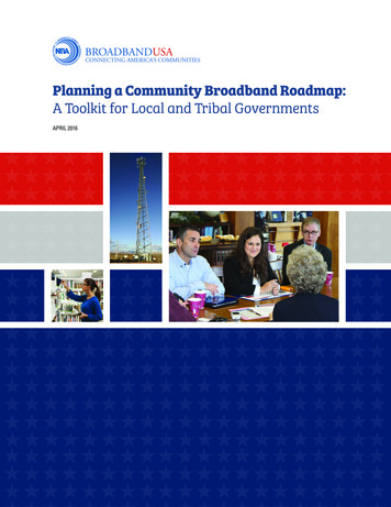
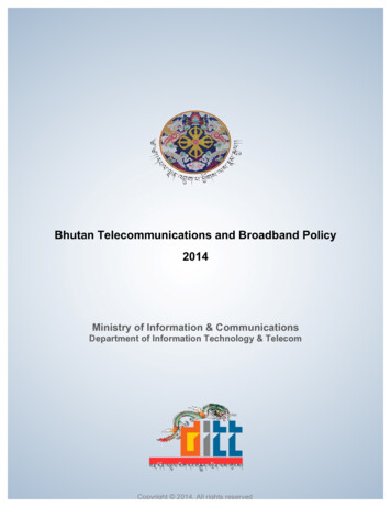
Cable descriptions—coaxial drop cableThe three types of cable used to carry broadband services to and within business and residences are coaxial, fiber optic and unshielded twistedpair (UTP). Coaxial cable is the most common; it is the “cable” in the term “cable TV.” The vast majority of broadband networks are constructedusing some type of coaxial cable. Coaxial is made up of these basic components:The center conductor carries a low-voltage RF or electronic digital signal and may also carry up to 150 volts of power (see Appendix/SafetyStandards/NEC Articles 820 and 830). For optimum strength and performance, CommScope uses copper-clad steel for our coaxial cable—other types (solid copper, silver-coated copper-clad steel) are available;The dielectric is a polymer insulation that supports the conductor.CommScope enhances the performance of its coaxial cable by usingfoamed (or cellular) dielectrics that offer lower loss;The shield defends the signal from RF interference. CommScope usesa foil/aluminum wire braid combination for long-term protection andperformance; our highest performance QR 320 cables use a welded andbonded .013-inch (0.3-mm) thick strip of aluminum as a shield. Shieldingcorrosion can be prevented with CommScope’s BrightWire treatment,and a braid shield impregnated with Migra-Heal flooding compound willresist moisture migration;The jacket protects the entire assembly. Jacketing materials will varydepending on the application—tough polyethylene (PE) is used for buriedinstallations; lower smoke-and-flame producing polyvinyl chloride (PVC)is used aerially and indoors, as are plenum-rated fluorinated ethylenepropylene (FEP) and polyvinylidene fluoride (PVDF).copper-coveredsteel conductorfoamed dielectricfoil/braid shieldcombinationmessenger wirejacketFor aerial installations, a messenger wire is built into the cable forsupport. CommScope also offers Multi-Reach cables that add up to sixvoice-grade UTPs for discrete phone service or powering.Braid shielding and coaxial cable performanceA coaxial cable must have, at minimum, a dual shield of aluminum foil tape overlaid with a woven braid of aluminum. This braid shield greatlyimproves the electrical and mechanical performance of the coaxial cable; in fact, a braid shield can vastly increase the installed life of thecable. All CommScope subscriber access coaxial cables use a combination of foil and braid shields.Braid shielding provides low frequency protectionFoil shielding is usually a layer of aluminum bonded to a polyester tape. It provides 100percent coverage over the dielectric and is best at preventing ingress and leakage ofhigh-requency signals; however, it is not that effective with lower frequency signals.Aluminum braid shielding complements foil by containing and preventing interferencefrom those lower frequencies.Braid shields increase cableperformance and can greatlyextend the useful life of the cableBraid shielding helps maintain dc resistanceFoil shielding is very flexible but lacking in mechanical strength. Stress caused by installation or by twisting and flexing over time (like in anaerial installation) will cause microscopic gaps to open in the foil. These “microcracks” degrade the electrical integrity of the foil and cause thedc resistance of the cable to rise. Resistivity gets worse as the cable twists.Strong, flexible braid shielding supports the foil and helps fight the formation of microcracks. The braid wires do not microcrack; they bridgethe gaps in the foil. Braid shielding keeps its integrity and delivers low and constant resistivity numbers even when twisting and flexing.Braid shielding keeps attenuation lowAttenuation performance goes hand in hand with dc resistivity; high resistivity caused by microcracks in the foil will result in higher attenuation.A history of 15,000 flexures can degrade a foil shield to the point where the calculated attenuation could worsen by 400 percent or more.However, the robust nature of the additional braid shield keeps attenuation low.Braid shielding keeps connectors connectedThe additional strength provided by braid shielding gives connectors something to hold onto. In terms of pulloff force, both compression andcrimp-fitted connectors hold much tighter to cables with braid shields.commscope.com5
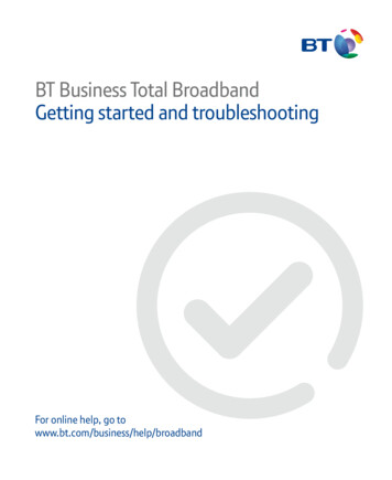
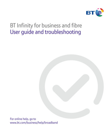
UTP indoor cableUnshielded twisted pair (UTP) cables consist of two insulated conductors twisted together in a very precise fashion; four of these pairs arethen jacketed together into a cable. The angle and number of the twists acts like a shield and helps the digital signal stay robust over longerdistances. UTP is used inside buildings to distribute voice and data signals over relatively short distances.Through advances in construction and materials, UTP cables have a much higher bandwidth (information carrying capacity) than theirtelephone wire cousins. Most UTP cables are defined by a “category” or a performance designation. The categories are roughly determined bythe bandwidth, or information-carrying capacity, of the cable. Category 5 (a data cable rated at 100 MHz of bandwidth) is the most commonlyused type in residences. For higher data speeds and increased bandwidth, CommScope also offers Ultra II enhanced Category 5E (200 MHz)and UltraMedia Category 6 (400 MHz) cables.Maintaining the twist is essential, especially during connectorization—the conductors must remain twisted right up to where they meet thejack. The loss of just one twist can degrade the performance of the cableso as to render it useless as a high-speed data cable.24 or 23 AWGsolid copper conductorspolyethyleneinsulationUTP cables consist of three basic components:4 twisted-paircomponentsThe conductor is 23 or 24 AWG solid bare copper;The insulation is usually a solid PE (foamed for UltraMedia) with FEPused in plenum cables; andThe jacket is a riser-rated PVC or plenum-rated FEP or PVDF. Becausethese cables are used indoors, pay special attention to the NEC rating ofthe application.PVC jacketCoaxial selection considerations—distanceCoaxial cable can be engineered for several levels of performance and cost-efficiency. For instance, a larger cable will carry a signal over alonger distance; additional shields provide more protection from interference. Your first consideration, however, is the overall distance of thedrop. CommScope offers cables tailored for different distances:QR 320—these are our highest performance coaxial cables and arerecommended for MDU usage (see Drop cable descriptions/specifications)or extremely long runs with their .071-inch (1.80-mm) copper-cladaluminum center conductor.F11 series cables—excellent-performing coaxial cables with a 14 AWG(1.63 mm) copper-clad steel center conductor. They are recommended foruse in runs of over 150 feet (45 meters).F6 series cables—these are made for shorter runs, with an 18 AWG (1.02mm) copper-clad steel center conductor. They are recommended for use inruns of 150 feet (45 meters) or less.These cables are available in constructions for aerial and buried outdoorinstallations. They are also available for residential and commercial indoor(general, riser and plenum) usage.Ask yourself three questions:what’s the distance, what’s theenvironment and how muchshielding is needed?commscope.comMaximum attenuation @ 68 FQR 320MHzdB/100'F11 seriesF6 series(dB/100m)50.24 (0.79)0.38 (1.25)0.58 (1.90)550.84 (2.76)0.96 ( 3.15)1.60 (5.25)831.07 (3.51)1.18 (3.87)1.95 (6.40)1.60 (5.25)1.75 (5.74)2.85 ( 9.35)2111.73 (5.68)1.90 (6.23)3.05 (10.00)2501.86 (6.10)2.05 (6.72)3.30 (10.82)3002.04 (6.69)2.25 (7.38)3.55 (11.64)3502.25 (7.38)2.42 (7.94)3.85 (12.63)4002.38 (7.81)2.60 (8.53)4.15 (13.61)4502.52 (8.27)2.75 (9.02)4.40 (14.43)5002.72 (8.92)2.90 (9.51)4.66 (15.29)181(F6 & F11 187)5502.85 (9.35)3.04 ( 9.97)4.90 (16.08)6002.98 ( 9.78)3.18 (10.43)5.10 (16.73)7503.34 (10.96)3.65 (11.97)5.65 (18.54)8653.62 (11.88)3.98 (13.05)6.10 (20.01)10003.89 (12.76)4.35 (14.27)6.55 (21.49)6
Coaxial selection considerations—shielding and environmentOnce you’ve determined which cable answers your need for signal over distance, you need to determine the type of cable you’ll need for theinstallation environment.For areas of possible RF interference, (pager antennas or other visible problem asoutlined on page 6 (Coaxial selection considerations—distance), or if there is a historyof customer comments concerning interference from ham radios, etc.), considerusing a tri-shielded cable (foil/60 percent braid/foil) shield. The extra layer of foilprovides additional protection against high-frequency RF signals at little additionalcost. Super-Shield (Quad) cables (foil/60 percent braid/foil/40 percent braid) provideoptimum protection against RF interference.Tri-shielded cables offer excellentRF protection at reasonable costFor aerial installations, select a messengered cable (also called a figure-8 cable) with a polyvinyl chloride (PVC) jacket. The messenger wire isa steel wire that is webbed together with the coaxial cable. This wire supports the coaxial cable—under no circumstances should subscriberaccess coaxial be run without a messenger or lashed to a wire.For buried installations, select a polyethylene-jacketed cable with MigraHeal flooding compound to prevent moisture ingress in case ofdamage. Article 830 considerations (see pages 16 and 34) make the use of cable pre-installed in conduit (CommScope’s ConQuest ) veryattractive.For cables that transition from outside to inside (from the ground block to the inside connection), select a CATV cable for residential use, orselect a CATV or CATVR cable for commercial buildings.For commercial installations, CATVR riser and CATVP plenum cables are required in certain circumstances. A riser-rated cable may be runvertically between floors; plenum cables are designed for use in air-handling spaces, such as the area above a hung ceiling. General-purposecables (CATV) may be run horizontally within or along walls and in raceways—they cannot transition between floors.For locations where salt or other aerial corrosives may be a problem, CommScope offers two aerial cable anti-corrosive treatments for braidshields: BrightWire , a dry treatment that chemically combines with metal components to protect against corrosion (and improve dc loopresistance); and APD (amorphous polypropylene drop), a nonflowing polypropylene flooding compound.QR 320 series selection matrix (MDUs and very long runs)This is a quick reference for QR 320 Series cables from CommScope. Answer the questions as you read along the diagram to arrive at theconstruction code for the cable required for your application.QR 320 cables have a unique welded aluminum strip shield for superior RF protection and a large center conductor for lower attenuation overlonger distances. We recommend them for use in MDUs.Underground QR 320 cables use MigraHeal flooding compound, which is applied under the jacket, making it suitable for direct burial.MigraHeal floodant is designed to flow into damaged jacket areas, sealing this area and inhibiting corrosion.commscope.com7
F11 Series selection matrix (runs over 150 feet/45 meters)This is a quick reference for F11 Series cables from CommScope. Answer the questions as you read along the diagram to arrive at theconstruction code for the cable required for your application.The XX in the part number should be filled with the code for the anti-corrosion agent you’d prefer as follows: BW for CommScope’s dryBrightWire , or APD for the more traditional APD flooding compound. All nonplenum high RF cables are tri-shielded (foil/60 percent braid/foil); super-shield versions are available. Plenum cables are available only with super-shields.commscope.com8
F6 Series selection matrix (runs 150 feet/45 meters or less)This is a quick reference for F6 Series cables from CommScope. Answer the questions as you read along the diagram to arrive at theconstruction code for the cable required for your application: The XX in the part number should be filled with the code for the anti-corrosionagent you’d prefer:BW for CommScope’s dry BrightWire , or APD for the more traditional APD flooding compound. All nonplenum high RF cables are trishielded (foil/60 percent braid/foil); super-shield versions are available. Plenum cables are available only with super-shields. A 90 percent braidis available for 2276K.commscope.com9
F11 Series selection matrix for NEC 830 (runs over 150 feet/45 meters)This is a quick reference for F11 Series cables that meet NEC 830. Answer the questions as you read along the diagram to arrive at theconstruction code for the cable required for your application: The XX in the part number should be filled with the code for the anti-corrosionagent you’d prefer:BW for CommScope’s dry BrightWire , or APD for the more traditional APD flooding compound. All nonplenum high RF cables are trishielded (foil/60 percent braid/foil); super-shield versions are available. Plenum cables are available only with super-shields.commscope.com10
F6 Series selection matrix for NEC 830 (runs 150 feet/45 meters or less)This is a quick reference for F6 Series cables meeting NEC 830. Answer the questions as you read along the diagram to arrive at theconstruction code for the cable required for your application: The XX in the part number should be filled with the code for the anti-corrosionagent you’d prefer:BW for CommScope’s dry BrightWire , or APD for the more traditional APD flooding compound. All nonplenum high RF cables are trishielded (foil/60 percent braid/foil); super-shield versions are available. Plenum cables are available only with super-shields. A 90 percent braidis available for 2276K.commscope.com11
UTP and fiber-optic cablesTwo factors control the selection for UTP and fiber-optic cables; the speed of the network they will support and the NEC rating required bythe installation.For UTP cables within the home, CommScope’s Category 5E UTP (product code UH58760) offers more than enough bandwidth for mostapplications. These cables meet the NEC CMR (riser) designation.If you are installing UTP in a commercial application (or require higher performance in a residential application), see the chart below:For fiber-optic cables within the home, we recommend a two-fiber interconnect with a riser rating using multimode fibers (construction codeR-002-IC-6F-FSDOR). A plenum version is available.Planning the runThe time you take in examining the site prior to installation is well spent and can help you avoid problems later on. You need to be aware ofissues such as right-of-way (ROW), where you will tap into the span, the distance of the run and where you will attach and bond the cable atthe customer’s structure. Refer to page 6 (cable selection) to determine what cable to use based on distance or NEC 830 considerations.Look for antennas to select cable shieldingA 60 percent braid/foil shield works for almost all CATV installations. If you are installing cable intended for a more active, two-way service(internet, high-speed data), you should consider a tri-shielded cable. Cellular and pager towers produce radiation that tends to raise havoc withCATV channels 19, 20 and 21. Ham radio aerials may also signify a problem. UrbanWhether the installation is aerialzones (like southern California or metropolitan New York) have inherently high levelsor buried, a simple site survey nowof RF pollution. We recommend tri-shielded cables with a minimum of 60 percentbraid for areas with high RF concentrations.can prevent headaches laterKnow your ROW (right-of-way)The most direct route may not be the legal route. Make sure the route you’re planningruns ONLY over the customer’s property. Generally, you can follow a parallel path to power or phone lines. However, under no circumstanceslash your drop to any other cable.Locate the tapWhile most spans have taps located next to the poles, you may occasionally find a tap in mid-span. This may be helpful in avoiding ROWissues.Select your attachment point for ease of bonding and accessNEC 820 specifies that coaxial cable must be bonded, preferably with the electrical. Therefore, try to attach the cable to the wall or cornernearest the meter. If that can’t be reached, an exterior cold water pipe (if the plumbing throughout the building and back to the main is entirelymetal) or an existing ground rod will do. If these are impractical, you will have to hammer in a ground rod. In most cases, you will be selectingthe cable entry point into the building; however, if the NIU is already in place, try to attach your cable as close to it as you can, keepingbonding considerations in mind.commscope.com12
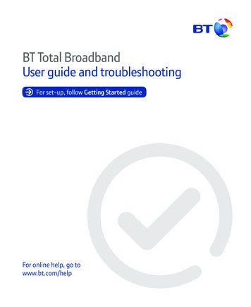
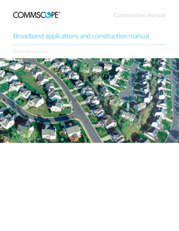
Attachment examples for aerial installationsThe top example shows a pretty straightforward installation.The electric meter is on the opposite side of the buildingfrom the span, so attachment near the the cold water tap isacceptable.The middle example shows that the most direct route wouldtrespass on neighboring property. Therefore, the dropshould be run along the span and then angle to the building,eventually running toward the meter and then back to thepoint of entry. Be sure to check mid-span; it is possible thatthere may be a tap there because a pole was there at one time.The bottom example is a tough call. It’s marginally shorter toattach near the point of entry, run to the meter for bondingpurposes and double back to the point of entry.In all cases, check your local coderequirements and system designspecifications for your prescribedbonding requirements.Aerial installation/messenger (figure-8) cableFor best efficiency and lowest cost, aerial installation is generally preferred. However, local or subdivision codes sometimes require that utilitiesbe installed underground. There are times the customer may want the cables hidden for aesthetic reasons. In these cases, see page 16 (buriedinstallation) for instructions on buried installations.A typical installation is shown below. A continuous length of cable runs from the tap to the attachment point and continues to the groundingpoint, called a ground/bond block. A second cable continues from the ground block through the point of entry to a termination point withinthe structure.Article 830 considerationsSome systems use coaxial or UTP cable to carry power as well as signal tothe NIU (network interface unit—sometimes called a NID/network interfacedevice). When installing powered coaxial cable (carrying up to 150 volts), payspecial attention to the cable-to-earth distance as shown in the diagram below.Tech tip: when pulling and hanging cable, avoid twisting,scraping, stepping on or crushing itNEC 830 also requires that cable attached to the building within 8 feet (2.5 meters) of grade must be placed within conduit, raceway or someother approved cable guard.NIUs and ground blocksNEC 830 installations will terminate at an NIU. Most NIUs have built-in connections that must be grounded at the meter or other approvedpoint. See page 20 (Attaching to the NIU—the 8 foot rule).commscope.com13
Pull the cable, separate the messengerSet up your cable pack or A-frame beneath the tap. Take the cable end andwalk toward the attachment point. Don’t let the cable kink, scrape, tangle orget hung up as you walk - it may deform the cable and cause transmissionproblems later.Tech tip: always pull more cable than you think you’llneedKeep pulling cable after you reach the attachment point. Remember, you need to have enough cable in hand to run along the soffit orfoundation line of the building to reach the grounding point.Go back to the reel and pull enough extra cable to reach the tap. Cut the cable at the reel.Separate the messenger from the coaxial cableUse your side cutters to start a split in the webbing between themessenger and the coaxial cable. Take the messenger in one hand andthe coaxial in the other and smoothly pull your hands apart to split thewebbing. Pull across the webbing (a scissors pull) instead of pulling thewebbing directly apart.Connectorize the cableAttach the connector per the instructions on page 26 (connectorizingbraid-shielded coaxial cable).Attach the messenger to a drop clamp1. Separate the messenger wire from the cable using the 90 (scissor) pullof the messenger and the cable, separating the length of messenger wireneeded to make the wrap; about 15 to 18 inches.Note: Never use the drop clamp, a knife, or other sharptool to separate messenger and cable.2. Fit the cable and messenger wire into the drop clamp as shown, so theclamp bail is between the two.3. Pull the messenger wire around the center of the bearing surface asshown, toward the rear or drop-side of the clamp.4. Serve the messenger wire through the messenger wire slots and beginthe wrap about the clamp body, as shown.5. Continue the messenger wire wrap for two full turns.6. Serve the messenger wire through the bottom messenger wire slot, asshown, to the drop-side of the clamp and cut the excess wire away, orground it to the strand.CommScope does not recommend the use of the 2-4-4 method or other methods of tying off the messenger around the cable. Studies haveshown that the cable’s impedance will change and worsen with loading.commscope.com14
Connect the coaxial to the tapThe cable should be connectorized per the instructions on page 26. Some systems like to protect the connection with a shield (a physicalcovering to protect against tampering). Place that over the connector now—you will require an F-connector tool to tighten the connection.With the messenger secured to the span, screw the connectorized cable into the tap hand-tight. Using a torque wrench, tighten the connectorto 30 lbs/in. If you don’t have a torque wrench, twist the connector an extra 1/4 turn with your wrench or F-connector tool to seat it. Coverthe connection with a boot.You should have about 2 feet (60 cm) of cable between the tap and where the cable joins the messenger. Along with the ease of handling thisprovides, this extra cable will be very useful if you ever need to re-connectorize the cable.Store this cable by forming a loop of about 6 inches (15 cm) in diameter. Make sure the diameter of the loop is no smaller than 10 times theouter diameter of the cable. Use cable ties to form and secure the loop to the span.Attach an identification tag to the cable.Attach the cable to the residenceUsing a ladder or a lift truck, climb up to the attachment point and screw or drive the P-hook or Q-hook into the residence. Use an insulatedhook if you are bringing in powered service per NEC 830. A good attachment point is the corner of the house under the soffit. NEVER attachto an antenna, rain gutter, chimney, power mast or lightning rod. The hook should be parallel to the ground.The attachment point should not be any closer than 4 inches (10 cm) from a telephone cableor 1 foot (30 cm) from a power line. Make certain you meet all clearance requirements.Taking the cable in hand, climb up to the attachment point. Pull the cable taut until the sag is1 percent of the overall length of the drop (examples: for a 100 foot run, the sag should be1 foot; for a 50 foot run, the sag should be 1/2 foot). Use your hand to mark the place onthe cable where the cable and the hook meet while maintaining proper sag. DO NOT pull thecable through the hook or attach it to the hook.Select a point on the cable at least 1 foot (30 cm) beyond where the cable and hook wouldmeet. Using side cutters, cut the messenger wire, being careful not to nick the jacket of thecoaxial cable. Pull the messenger and the coaxial apart to produce over 1 foot (30 cm) ofmessenger. Shear, don’t tear, the cable (see page 13).commscope.com15
Run the cable to the grounding block or NIUUsing the 2-4-4 method described on page 15, attach the messenger wire to the hook (or use a messenger wire clamp). Strip the remainingmessenger wire from the coaxial.Route the cable from the attachment point to the grounding block or the entry point for the NIU. The path should follow the architecturaldetails of the residence, running down at the corners and across at beams and seams in the siding.Use cable clips to attach the coaxial to the house. A variety of screw-in or nail-in clips are available for wood and masonry. Special snap-in clipsare available for vinyl and aluminum siding. Never staple coaxial cable. Stapling will deform the dielectric and may damage the shield; in eithercase, a loss of performance will result and you will have to replace the cable.Place your first clip so as to allow for a small drip loop. Then place theclips about every 3 feet (1 meter) for vertical runs and no farther apartthan 18 inches (.5 meters) on horizontal runs.Make sure you do not kink or bend the coaxial cable tighter thanthe recommended bend diameter (usually 10x its outer diameter—check your cable specs to be certain). All coaxial connections to thegrounding block or splitters must be horizontal.If connecting to a ground block, proceed to page 19 (attach thecable to the ground block/aerial installation). If connecting to an NIU,proceed to page 20 (attaching to the NIU—the 8 foot rule).For NEC 830, use an insulatedhook for attaching themessenger wireBuried installationUnderground service has become popular in many developments and subdivisions. Broadband services are brought in by buried cable, andaccessed by pedestals which are usually at the property line.While the easiest way to run the cable is to trench or plow in a burial-grade coaxial cable to a minimum depth of 12 inches (.3 m), buryingcable preinstalled in conduit is a far better method. Cable in conduit (CIC) offers greater physical protection against environment, abrasion,rocks,
The three types of cable used to carry broadband services to and within business and residences are coaxial, fiber optic and unshielded twisted pair (UTP). Coaxial cable is the most common; it is the "cable" in the term "cable TV." The vast majority of broadband networks are constructed using some type of coaxial cable.