Transcription
ROLLER CONEDULL GRADINGMANUAL
Roller Cone Dull Grading ManualThe Smith Bits definitions and guidelines shownwithin are NOT IADC standards. They were createdsolely for internal purposes to reduce ambiguitiesand to improve our consistency in grading dull bitswithin the current IADC structure.P.O. Box 60068 Houston, Texas 77205-0068U.S. And Canada: 800/US SMITH Tel. 281/443-3370Fax: 281-233-5237 Internet: http://www.smithbits.comCopyright 2008 Smith International, Inc.All rights reserved.ST-2067 25M 01/08
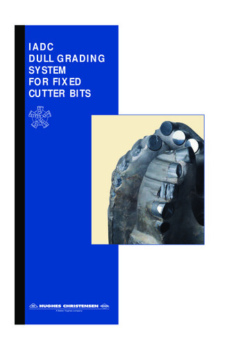
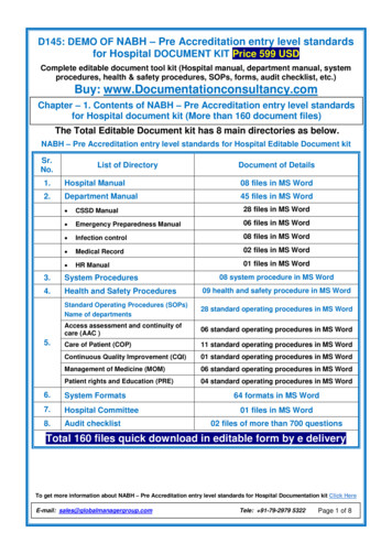
System StructureBTGREMARKS145632BCUTTING STRUCTUREGInner Outer Dull Loca- Brng. GaugeRows Rows Char. tion Seal 1/16(I)(O)(D)(L)(B)(G)78REMARKSOther ReasonDull Pulled(R)(O)1: (I) Inner Rows Used to report the condition of the cutting elementsnot touching the wall of the hole. Linear scale from 0 - 8 measuring the combinedcutting structure reduction due to lost, worn and/orbroken cutting elements.2: (O) Outer Rows Used to report the condition of the cutting elementsthat touch the wall of the hole. Linear scale from 0 - 8 measuring the combinedcutting structure reduction due to lost, worn and/orbroken cutting elements. Smith Bits guideline - Do not include heel elements.TOOTH HEIGHT MEASUREMENTT3 T4 T5T2T1T0 - NEWT6T7T8
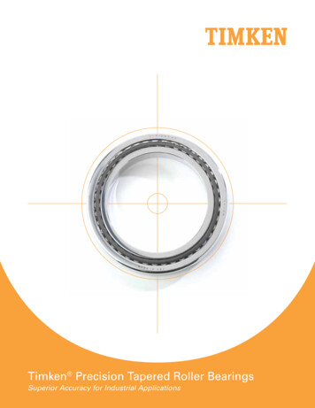
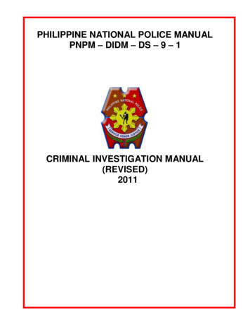
Roller Cone Dull Grading ManualIdentifying TCI and Milled Tooth Bit RowsHeel RowGauge RowInner RowConventional Cutting StructureHeel RowGauge RowInner Row(off-gauge)TrucutTM Cutting Structure
Heel RowGauge RowInner RowConventional Cutting StructureHeel RowGauge RowInner Row(off-gauge)TrucutTM Cutting Structure
Roller Cone Dull Grading Manual3: (D) Dull CharacteristicsUses a two letter code to indicate the major dull characteristic of the cutting structure.DULL CHARACTERISTICS* BC — Broken ConeLT — Lost Teeth / Cutters# BF — Bond FailureNO — No DullBT — Broken Teeth /CharacteristicsCuttersOC — Off Center WearBU — Balled Up BitPB — Pinched Bit* CC — Cracked ConePN — Plugged Nozzle /* CD — Cone DraggedFlow PassageCI — Cone InterferenceRG — Rounded GaugeCR — Cored# RO — Ring OutCT — Chipped Teeth /SD — Shirttail DamageCuttersSS — Self-SharpeningER — ErosionWearFC — Flat Crested WearTR — TrackingHC — Heat CheckingWO — Washed Out BitJD — Junk DamageWT — Worn Teeth / Cut* LC — Lost ConetersLN — Lost Nozzle* Show cone # or #’s under location 4.# Not used for roller cone bits. Smith Bits guideline - input only one dull characteristiccode. Smith Bits definition - The cutting structure dull characteristic is that observed cutting structure dull characteristic that would most likely limit further usage of the bit forthat application. This column is only for codes that apply to cutting structures.4: (L) LocationUses a letter or number code to indicate the location onthe face of the bit where the cutting structure dull characteristic occurs.LOCATION - ROLLER CONE BITSNMGA— Nose Row— Middle Row— Gauge Row— All RowsCone #123 Generally, the #1 cone contains the centermost cutting element. The #2 and #3 cones follow in a clockwiserotation. However, accurate determination of the #1 cone,on any roller cone bit by visual examination alone, is notalways possible. G Gauge - those cutting elements which touch thehole wall. N Nose - the center most cutting elements of the bit. M Middle - the cutting elements between the nose andthe gauge.
A All rows Cone numbers Smith Bits guidelines - a maximum of two characters tobe input.5: (B) Bearings / SealsNon-Sealed BearingsLinear scale from 0 - 8 estimating bearing life used.Sealed BearingsE - Seals effectiveF - Seals failedN - Not able to gradeSmith Bits guidelines This column is used to indicate condition of the bearingand seal assembly. If either component in the assemblyhas failed, then the code is F. If any portion of the bearing is exposed or missing, it isconsidered an ineffective (F) assembly. Use N if unable to determine the condition of both components. Smith Bits grades each assembly separately. If grading all assemblies as one, list the worst case.Sealed Bearing ChecklistItems To Check When DeterminingSeal / Bearing Effectiveness Ability to rotate coneCone springbackSeal squeakInternal soundsWeeping grease Shale burnShale packingGaps - backface or throatBearing letdown - inner orouter6: (G) GaugeUsed to report the undergauge condition of the cutting elements that touch the wall of the hole. Use only a nominal ring gauge to gauge a dull bit. New bits are built to API specifications. Ring gaugesbuilt for new bits have the tolerances listed in the tablebelow and should not be used for gauging dull bits.API Tolerance For New BitsBit SizeAPI Tolerance5 5/8 - 13 3/4 1/32 : -014 - 17 1/2 1/16 : -017 5/8 & larger 3/32 : -0
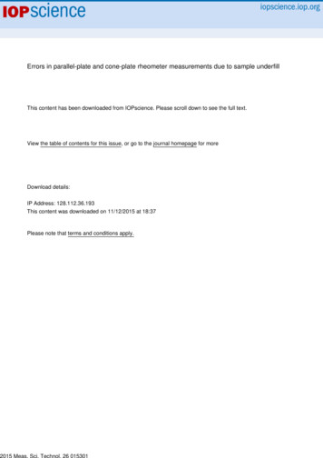
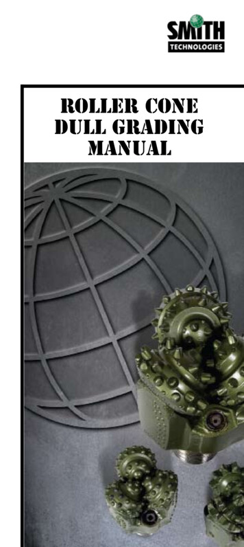
Roller Cone Dull Grading ManualMeasured Distance3 Cone BitsAMOUNT OUT OF GAUGE MEASURED DISTANCE X 2/3Smith Bits guidelines Round to nearest 1/16”. Bits with bearing/seal failures: can measure amountout of gauge as long as cones do not have any axial orradial movement. Measurement to be made on either gauge or heel elements which ever is closer to gauge. Applies to cutting structure elements only. Ensure that a nominal ring gauge is used. If nominalring gauges are not available, true gauge condition cannot be determined.Measured Distance2 Cone BitsAMOUNT OUT OF GAUGE MEASURED DISTANCE7: (O) Other Dull CharacteristicsUsed to report any dull characteristics.DULL CHARACTERISTICSBC — Broken ConeLT — Lost Teeth / Cutters# BF — Bond FailureNO — No DullBT — Broken Teeth /CharacteristicsCuttersOC — Off Center WearBU — Balled Up Bit* PB — Pinched BitCC — Cracked Cone* PN — Plugged Nozzle /CD — Cone DraggedFlow PassageCI — Cone InterferenceRG — Rounded GaugeCR — Cored# RO — Ring OutCT — Chipped Teeth /* SD — Shirttail DamageCuttersSS — Self-SharpeningER — ErosionWearFC — Flat Crested WearTR — TrackingHC — Heat Checking* WO — Washed Out BitJD — Junk DamageWT — Worn Teeth / CutLC — Lost Coneters* LN — Lost Nozzle* Used only in the ‘Other Dull Characteristics’ column.# Not used for roller cone bits.
8: (R) Reason PulledUsed to report the reason �————————Change Bottom Hole AssemblyCondition MudCore PointDownhole Motor FailureDrill PlugDrill String FailureDrill Stern TestingDownhole Tool FailureFormation ChangeHole ProblemsHours on BitLeft in HoleRun LogsPump PressurePenetration RateRig RepairRetrieve SurveyTotal Depth / Casing DepthTorqueTwist OffWeather ConditionsWashout in Drill String
Roller Cone Dull Grading ManualBC - Broken ConeThis describes a bit with one or more cones that have been brokeninto two or more pieces, but with most of the cone still attached to thebit. Cone shell peeling is considered to be a broken cone.POTENTIAL CAUSESCracked cone Progression from a cracked cone. See respective section.Excessive impact load / improper drilling practices Dropping of the drill string. Tagging bottom too hard or intentional spudding. Hitting a ledge while tripping or making a connection. Running on junk.Reduction in cone shell thickness Cone Interference - see respective section. Erosion - see respective section. Tracking - see respective section. Off Center Wear - see respective section.Drilling environment Hydrogen sulfide embrittlement. Corrosion.
BROKEN CONE - BCAPPLICATION RECOMMENDATIONSExcessive impact load / improper drilling practices Follow proper drilling practices.Drilling environment Follow recommended drilling fluid guidelines.
Roller Cone Dull Grading ManualBT - Broken TeethA cutting element is considered broken if over 1/3 of the cutting element is missing regardless of the cause. In some formations, brokenteeth can be a typical dull characteristic for tungsten carbide insertbits if performance meets established standards. However, BT maybe a potential indicator of problems in bit selection or operating practices if performance falls significantly short of expectations. Brokenteeth is not a typical dull characteristic for steel tooth bits and mayindicate an improper application or improper operating practices.POTENTIAL CAUSESFormation / improper bit selection No specific breakage pattern. Typically an overload. Occurswhen the compressive strength of the formation exceeds designcriteria.Excessive WOB for application and specific bit type Indicated by broken teeth predominantly in the middle rows, butcan also occur in the nose rows.Excessive RPM for application and specific bit type Indicated by broken teeth predominantly in the gauge row due tohigh relative velocities and impact force generated .Broken formations (includes boulders) Broken formations are those that have alternating hard andsoft interbedded laminated sections with distinct well definedboundaries laid down at an angle. As drilling progresses throughthe bedding planes, pieces break at the bedding planes causinguneven loading on the cutting structure as the broken portions offormation move or roll under the bit.Improper bottom hole pattern break-in Excessive WOB and RPM and the previous bits’ bottom hole pattern can create high cutting structure loading causing broken teethunless the bit can create its own bottom hole pattern.Excessive impact load / improper drilling practices Dropping of the drill string. Tagging bottom too hard or intentional spudding. Hitting a ledge while tripping or making a connection. Running on junk.Cone interference See respective section.Heat checking Heat checking generates stress risers allowing breakage at lowerenergy levels. See respective section.
BROKEN TEETH - BTRounded gauge The cross-section is worn to the extent it is insufficient to withstand applied drilling loads. See respective section.Erosion Cutting elements effectively become longer due to cone shell erosion. By increasing the effective extension, the cutting elementbecomes easier to break. See respective section.APPLICATION RECOMMENDATIONSFormation / improper bit selection Select a bit with less offset, and/or less tooth extension, and/orgreater tooth count, and/or tougher tooth shape.Excessive WOB for application and specific bit type Use proper WOB for formation. Use a shock sub when anticipating numerous formation changes.See broken formations. For hard formations, select a bit with less offset, and/or less toothextension, and/or greater tooth count, and/or tougher tooth shape.Excessive RPM for application and specific bit type Use proper RPM for formation. For hard formations, select a bit with less offset, and/or less toothextension, and/or greater tooth count, and/or tougher tooth shape. Can also be caused by heat checking or gauge rounding. Seerespective sections.Broken formations (includes boulders) Broken teeth due to drilling broken formations can occur in anyrow. This can be excessive WOB or RPM related. An indicatorof broken formations is when the torque becomes extremely erratic when drilling through the boundaries, then smooths out. Usea shock sub.Improper bottom hole pattern break-in Bottom hole pattern break-in is considered to be when a new bitachieves uniform cutting structure loading. This is done withlight weights and slow RPM and is normally achieved within3 to 6 inches. At that point WOB and RPM can be graduallyincreased to typical operating levels.Excessive impact load / improper drilling practices Follow proper drilling practices.
Roller Cone Dull Grading ManualBU - Balled UpBit balling is a condition where formation becomes packed betweenthe cones and bit body or between the cutting elements such that theROP suffers. There may or may not be any evidence of skidding orphysical damage to the bit. The cutting elements are packed off tothe extent that they are not penetrating into the formation effectively.Rotary torque will typically decrease as the bit balls up.POTENTIAL CAUSESFormation Drilling a sticky formation (e.g., gumbo, hydratable shales).Inadequate hydraulics Poor hole cleaning and/or bit cleaning for penetration rateachieved with the WOB and RPM combination used.Poor fluid distribution Improper nozzle configuration or nozzle type selection.Improper drilling practices Forcing the bit into formation cuttings with the pump not running. Inadequate cleaning of the hole while making a connection.Improper bit selection Harder bit types have less optimal cleaning attributes. These bitsgenerally have greater tooth count and/or shorter teeth which areeasier to pack off. They also provide less flow area on the holebottom.Drilling environment Poorly maintained or not optimized drilling fluid. Improper drilling fluid.
BALLED UP - BUAPPLICATION RECOMMENDATIONSFormation See all the following.Inadequate hydraulics Ensure that the hydraulics have been optimized for the parametersavailable. Increased hydraulic energy is needed to address this condition.Poor fluid distribution For all bit balling problems, center jets are recommended toenhance cone cleaning. Full-extended nozzles enhance hole bottom cleaning but canslightly reduce cone cleaning since the fluid from the nozzle exit,is so close to the hole bottom, that it may create less turbulenceand fluid entrainment around the cones. Mini-extended nozzles can slightly reduce cone cleaning dueto less fluid diffusion from this nozzle type. Also, extendingthe nozzle exit closer to the hole bottom can slightly reduce theturbulence and fluid entrainment around the cones. Crossflow and asymmetrical nozzle configurations typically provide better bottom hole cleaning and can influence cone cleaningas well.Improper drilling practices Follow proper drilling practices.Improper bit selection Select bits with less flow restrictive cutting structures. These willtypically be more aggressive types and for milled tooth bits, mayhave a combination of the following: Narrow crest widths on gauge, specifically no T or L shapedgauge teeth or web gauge structures. Gauge and adjacent rows with tooth de
Roller Cone Dull Grading Manual BU - Balled Up Bit balling is a condition where formation becomes packed between the cones and bit body or between the cutting elements such that the ROP suffers. There may or may not be any evidence of skidding or physical damage to the bit. The cutting elements are packed off toFile Size: 1MBPage Count: 103