Transcription
HomeSearchCollectionsJournalsAboutContact usMy IOPscienceErrors in parallel-plate and cone-plate rheometer measurements due to sample underfillThis content has been downloaded from IOPscience. Please scroll down to see the full text.2015 Meas. Sci. Technol. 26 5301)View the table of contents for this issue, or go to the journal homepage for moreDownload details:IP Address: 128.112.36.193This content was downloaded on 11/12/2015 at 18:37Please note that terms and conditions apply.
Measurement Science and TechnologyMeas. Sci. Technol. 26 (2015) 015301 (4pp)doi:10.1088/0957-0233/26/1/015301Errors in parallel-plate and cone-platerheometer measurements due tosample underfillLeo H O Hellström, Mohamed A Samaha1, Karen M Wang,Alexander J Smits2 and Marcus HultmarkDepartment of Mechanical and Aerospace Engineering, Princeton University, Princeton, NJ 08544, USAE-mail: lhellstr@princeton.eduReceived 8 September 2014, revised 17 October 2014Accepted for publication 28 October 2014Published 24 November 2014AbstractThe effect of sample underfill on parallel-plate and cone-plate rheometers is examined.Sample underfill can be caused by incomplete filling of a sample or loss of fluid during a testby, for example, evaporation. It is shown that even a small degree of sample underfill canlead to significant errors in measuring viscosity. A method is proposed to reduce these errorsby directly monitoring the sample radius over the full course of the test. It is shown that theaccuracy of the rheometer even while testing simple fluids like water is greatly improved.Keywords: rheometer, sample underfill, evaporation1. Introductionknowing the exact radius of the sample, as long as the radiusis much larger than that of the stem. This method is unsuitable for low viscosity systems and polymer solutions wherethe small gap between the stem and annulus is penetrated byfluid, causing additional friction. The proposed design is alsolimited to rheometers with a non-displacing force measuringcell, since the sensing area of the stem must not move relativeto the fixed annulus [10].Here, we address the errors due to under-filling in measuring the viscosity of homogeneous liquids. We show that theseeffects can be significant for both parallel plate and cone plategeometries, and propose a method to account for such errors.The proposed method is suitable for any parallel plate or coneplate rheometer where there is visual access to the sample.Errors in parallel disk rheometry can arise from many sources,such as uncertainties in the gap size [1], lack of parallelism inthe plates [2], viscous heating effects [3], and wall-slip errors[4]. However, the two main failures in rotational rheometersare considered to be edge failure [5, 6] and radial migration,both associated with the dynamics of the interface at the rim[7]. Here, we address an additional interfacial error: sampleunderfill, a condition where the sample boundary radius is lessthan that of the disk and the volume between the disks is notentirely filled.One of the causes of sample underfill is evaporation. Itis possible to avoid the effects of evaporation by creating anenclosure with a saturated environment [8], but this techniquecan cause condensation if cold-spots are present [9]. Schweizer[10] addressed this problem by manufacturing a partitionedmeasuring head consisting of a central stem surrounded by anannulus, where only the torque on the stem is measured andthe surrounding annulus limits any effects of under-filling.As a consequence, measurements may be achieved without2. AnalysisA general derivation of the relationship between the torque Tand the shear stress is given by Macosko [6]. Since the apparentshear stress is affected by the degree of sample underfill, weextend this derivation to relate the torque to the apparent viscosity. The torque measured by a rheometer is given by:1Present address: Department of Mechanical Engineering, Rochester Institute of Technology—Dubai, PO Box 341055, UAE.2Present address: Department of Mechanical and Aerospace Engineering,Monash University, VIC 3800, Australia.0957-0233/15/015301 4 33.00 1T 2π 0Rτr 2 dr 2015 IOP Publishing Ltd(1)Printed in the UK
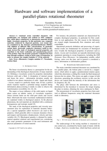
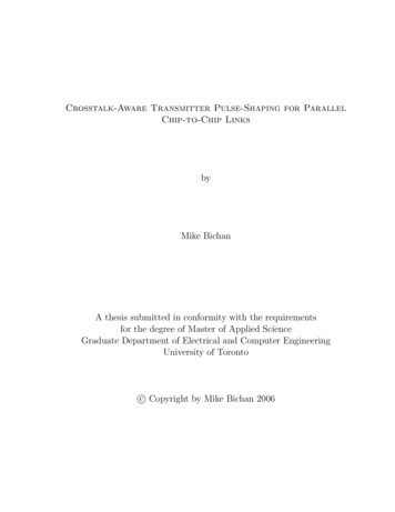
L H O Hellström et alMeas. Sci. Technol. 26 (2015) 015301 R 3μ Tη c c 1 c 1 (ηc 1) 1 3δ, R0 μT0where τ is the local, axisymmetric, shear stress, r is the radialdistance from the center of rotation, and R is the sample radius.For a fluid with a linear velocity profile between the upper andlower plates, the shear stress can be described as:τ μ Ur μω yh (r )where the final approximation is found using the binomialtheorem for small η and changes in radius, δ (1 R/R0). Bymeasuring the radius R simultaneously with the torque, equations (5) can be used to estimate the true viscosity.(2)where μ is the apparent viscosity, U is the azimuthal velocity, yis a rotational axial coordinate and U/ y is the local velocitygradient across the gap, ω is the angular velocity, and h(r)is the local gap height. For the parallel-plate and cone-plategeometries, h p αp(3a) h c αc βcr,(3b)3. Experimental procedureThe effects due to under-filling were measured using anAnton-Paar GmbH. Physica MCR 301 rheometer with atorque sensor accuracy of 0.2 µN m or 0.5%, whichever ismore conservative (as given by the manufacturer). The rheometer has two discs separated by a fluid-filled gap wherethe lower disc is stationary and temperature controlled to be20 0.2 C. The upper disc rotates at a prescribed angularvelocity and uses an air bearing to minimize friction. Theexperiment was conducted using two different configurations. First, a 49.966 mm diameter parallel plate configuration (PP50) was used with a 1 mm gap height. Second, a coneplate configuration (CP50-1/TG) was used with a 49.962 mmdiameter and a 0.979 cone angle. The cone tip is truncatedby 49 µm to allow the virtual tip of the cone to coincide withthe surface of opposing plate without added friction, givingαc 0 in equation (3b).The tests were conducted for three pure fluids: water, ethanol, and isopropyl alcohol. The volume between the plateswas first completely filled by the sample fluid. The experimentwas then commenced, and the sample radius was altered overthe course of the experiment by allowing the fluid to evaporate. Evaporation was the sole method by which the samplevolume was altered, and the fluids were chosen such that theirproperties remained insensitive to evaporation. The radius ofthe sample R was recorded using a Nikon D7100 SLR camerawith an AF-S Micro Nikkor 85 mm lens, which has a resolution of 9.95 µm/pixel. The experiments involving water werecarried out for 45 min while an image was taken every minute.For the more volatile fluids, ethanol and isopropyl alcohol, theexperiments were performed over a period of 10 min with animage taken every 10 s. Figure 1 shows the experimental setupfor a parallel plate with water as the sample fluid. Figure 1(a)is the initial condition and figure 1(b) shows the sample after45 min where the radius has decreased by approximately 3% .The sample radius was determined by measuring the distancebetween the waists of the two opposing menisci to the centerof the rheometer setup, resulting in a left and right radius (RL,RR). The radial migration was monitored by the change in theratio RL/RR between two consecutive images. Once this difference exceeded 0.3%, all remaining data in the time serieswere disregarded.where α and β are constants, and the subscripts p and c indicate parallel-plate and cone-plate geometry, respectively. Thetotal torque is then given byTp 2πμω Tc 2πμω 0R 0R1 πμω 4r3dr R2 αpαp(4a)r3drαc βcr 1β αα2α3 R3 c2 R2 c3 R c4 ln 1 c R 2πμω 2βcβcβcαc 3βc(4b)(see also Lee et al [11]).For a typical cone-plate rheometer, R αc/βc, and onlythe leading order term need be retained in equation (4b). Theviscosity is then found according to μp 2 Tpα pπ ωR 4(5a) μc 3 Tcβc2π ωR3(5b)where R is the liquid boundary radius, being R0 in the fullyfilled case and R R0 when underfilled. The resulting relativeerror, η, in the apparent viscosity can be written as ηp ηc Tp R0 4 1T0 R (6a)μcT R 3 1 c 0 1,T0 R μ(6b)μpμ 1 where μp and μc are the measured apparent viscosities, andsubscript 0 indicates a value for a properly filled setup. Weinvestigate how under-filling affects the viscosity measured byan operator who assumes erroneously that R R0. In this case,the relative viscosity error can be written asμ p R 4Tpη p 1 1 ηp 1 1 4δ R0 μT0()(7b)4. Results and discussionFigure 2 shows the percentage deviation in the apparent viscosities (η and η ) as a function of the change in the sample radius,δ. The three data sets for water, ethanol, and isopropyl alcohol(7a)2
L H O Hellström et alMeas. Sci. Technol. 26 (2015) 015301Figure 1. Rheometer setup for a parallel plate head, (a) properly filled sample, (b) under-filled sample.2(b)21100 1 1(η c , η c ) 100(ηp , η p ) 100(a) 2 3 4 4 51 6 3 3 41 5 6 7 8 2 700.511.5% error in radius, δ 1002 82.500.511.5% error in radius, δ 10022.5Figure 2. Percent error in measured viscosity for increasing error in radius, δ (1 R/R0). (a) Parallel plate (ηp and η p, see equations (6a)and (7a); (b) cone plate (ηc and η c, see equations (6b) and (7b). Here, , Δ and represents water, ethanol and isopropyl alcohol,respectively. Open symbols represent η , assuming constant radius R0. Filled symbols, η, use instead the wetting radius R, as recorded by thecamera. Dashed lines show the expected behavior for small errors.displaced towards areas with higher shear stress, resulting in ahigher measured torque.were post-processed using the two different methods shownin equations (6) and (7). We note first that the results for thethree different fluids agree well, showing a fluid-independentbehavior. Second, the errors due to under-filling follow theexpected behavior for small deviations. Most importantly, thedifferences between η and η represent the errors introducedin the measurement of viscosity by neglecting the effects ofunder-filling. Specifically, we see that in our experiments onwater, ethanol and isopropyl alcohol, up to 7% bias errorswere incurred due to the change in radius of the sample duringthe tests. We also see that by accounting for this under-fillingby using the measured sample radius eliminates the bias error,leaving a random error in the viscosity of less than 1%.The significance of under-filling can also be demonstrated bynoting that a 100 µm change in the radius of the sample (corresponding to a 0.2% variation) will cause a 1.6% error in theapparent viscosity for a parallel plate setup, and 1.2% for acone plate setup.Note that the method presented here is limited to cases ofunder-filling with centered sample placing. For uncenteredsample placing, or radial migration, parts of the sample is5. ConclusionsSmall changes in the radius of a rheometer sample can causesignificant errors in the measured apparent viscosity. Theseerrors can be accounted for by adopting the following procedure, which can also be used to verify the initial sampleradius and to estimate the effects due to under-filling. First,image the sample and estimate the true radius from the image.Second, if there is under-filling, either caused by evaporationor other means, verify that the sample remains centered bycomparing the meniscus recession at both sides of the image.Third, use equation (5) to calculate the correct viscosity usingthe measured sample radius. Note that most rheometers keepthe angular velocity constant, not the shear rate.Although we have assumed a Newtonian stress, our analysis could be simply extended to examine, for example, theviscoelastic properties of polymers using small amplitudeoscillatory shear measurements.3
L H O Hellström et alMeas. Sci. Technol. 26 (2015) 015301Acknowledgments[4] Kiljański T 1989 A method for correction of the wall-slipeffect in a couette rheometer Rheol. Acta 28 61–4[5] Carvalho M S, Padmanabhan M and Macosko C W 1994Single-point correction for parallel disks rheometry J.Rheol. 38 1925–36[6] Macosko C W 1994 Rheology: Principles, Measurements, andApplications (Advances in Interfacial Engineering) (NewYork: Wiley)[7] Connelly R W and Greener J 1985 High-shear viscometry witha rotational parallel-disk device J. Rheol. 29 209–26[8] Magnin A and Piau J M 1990 Cone-and-plate rheometry ofyield stress fluids. Study of an aqueous gel J. Non-Newton.Fluid Mech. 36 85–108[9] Sato J and Breedveld V 2005 Evaporation blocker for coneplate rheometry of volatile samples Appl. Rheol.15 390–7[10] Schweizer T 2004 A quick guide to better viscositymeasurements of highly viscous fluids Appl. Rheol.14 197–201[11] Lee C, Choi C-H and Kim C-J 2008 Structured surfaces for agiant liquid slip Phys. Rev. Lett. 101 064501This work was supported under ONR MURI Grants N0001412-1-0875, N00014-12-1-0962, and N00014-13-1-0458 (Program Manager Dr K-H Kim). The authors would like to thankHoward Stone for making the rheometer and the resources ofhis laboratory available.References[1] Davies G A and Stokes J R 2005 On the gap error in parallelplate rheometry that arises from the presence of air whenzeroing the gap J. Rheol. 49 919–22[2] Clasen C 2013 A self-aligning parallel plate (SAPP) fixture fortribology and high shear rheometry Rheol. Acta 52 191–200[3] Yesilata B 2002 Effect of viscous dissipation on polymericflows between two rotating coaxial parallel discs Int.Commun. Heat Mass Transfer 29 589–6004
tions. First, a 49.966 mm diameter parallel plate configura-tion (PP50) was used with a 1 mm gap height. Second, a cone plate configuration (CP50-1/TG) was used with a 49.962 mm diameter and a 0.979 cone angle. The cone tip is truncated by 49 µm to allow the virtual tip of the cone to coincide withFile Size: 610KBPage Count: 5