Transcription
IADCDULL GRADINGSYSTEMFOR FIXEDCUTTER BITS A Baker Hughes company
INTRODUCTIONInformation provided by dullgrading bits can be very significant.This value was recognized by theIADC some 25 years ago when aworldwide dull grading systemfor roller cone bits was established.For fixed cutter bits - that is,all non-roller cone bits - this dullgrading system could not be applied,and a new system had to be established. The fixed cutter dull gradingsystem was developed by the IADCDrill Bits Sub-Committee in 1987 andrevised in 1991.The fixed cutter dull grading system can be used for all non-rollercone bits, including natural diamond, polycrystalline diamondcompacts (PDC), thermally stablepolycrystalline (TSP) diamonds,impregnated bits, core bits and nonroller cone bits which do not employ diamond material as a cuttingelement.The system does not distinguishbetween drilling and coring bits.This guide will only show examplesof PDC, TSP, natural diamond andimpregnated or sintered drill bits.
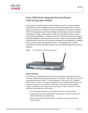
SYSTEM STRUCTUREThe Dull Grading System Chartadopted by IADC includes all codesnecessary to dull grade roller conebits and fixed cutter bits.The chart describes eight factorson drill bits. The first four spacesdescribe the “Cutting Structure”. Thefifth space (“B”) refers to “BearingSeals” and does not apply to fixedcutter bits. This space is alwaysmarked with an “X” when fixedcutter bits are graded. The sixthspace (“G”) refers to “Gauge Measurement” while the last two “Remarks” spaces indicate “Other DullCharacteristics” (or secondary dullcharacteristics) and “Reason Pulled”.Inner/Outer RowsUsing a linear scale from zero toeight, a value is given to cutters inthe inner and outer rows of surfaceset bits to indicate the amount ofwear. Grading numbers increasewith amount of wear, with “zero”representing no wear and “eight”meaning no usable cutter left.Accordingly, “four” indicates 50%wear.PDC cutter wear is measured in alinear scale from one to eight acrossthe diamond table, regardless of thecutter shape, size, type or exposure.Figure 1 illustrates the cutter weargrading system schematically.IADC DULL GRADING SYSTEM CHARTCutting risticsXFIGURE 1INNER AREA2/3 RADIUSOUTER AREA1/3 RADIUSWhen grading a dull bit, the average amount of wear for eacharea should be recorded. As shown above, 2/3 of the radiusrepresents the “inner rows”. The five cutters in this areawould be graded “two”. This is calculated by averaging theindividual grades for each cutter in the area:(4 3 2 1 0) 250000The average wear for the “outer” area is calculated in the samemanner:(5 6 7) 63000“Six” would be the average wear gradient for the outer area.This information can now be transferred to the IADC DullGrading System Chart above.NOTE: For a core bit, the centerline in Figure 1 would be theinside of the core bit ID.ReasonPulled
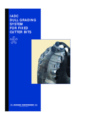
Dull Characteristics /Other CharacteristicsThe third and seventh spaces are foruse in noting dull characteristics ofthe bit, i.e., the most prominent physical changes from its new condition.Codes for these characteristics arelisted below in Table 1. In general,four different wear characteristicscan be distinguished for fixed cutterbits, as shown in Figures 2A and 2B.TABLE 1.DULL/OTHER CHARACTERISTICS*BC BF BT BU *CC *CD CI CR CT ER FC HC JD * LC LN LT NO NROCPBPN-RG RO RR SD SS TR WO WT -Broken ConeBond FailureBroken Teeth/CuttersBalled UpCracked ConeCone DraggedCone InterferenceCoredChipped Teeth/CuttersErosionFlat Crested WearHeat CheckingJunk DamageLost ConeLost NozzleLost Teeth/CuttersNo Major/Other DullCharacteristicsNot RerunnableOff-Center WearPinched BitPlugged Nozzle/Flow PassageRounded GaugeRing OutRerunnableShirttail DamageSelf Sharpening WearTrackingWashed Out BitWorn Teeth/Cutters*Show cone number(s) under “Location”.NOTE: If no “Dull Characteristic” is visible,mark this space “No”. If no “Other Characteristic” is visible, mark this space “No”.IADC DULL GRADING SYSTEM CHARTCutting risticsReasonPulledXFIGURE 2A. STUD CUTTERSFIGURE 2B. CYLINDER CUTTERSDull grading characteristics are based on PDC or stud wear, but also apply forTSP or Natural Diamond material. See photographs on the following pages.
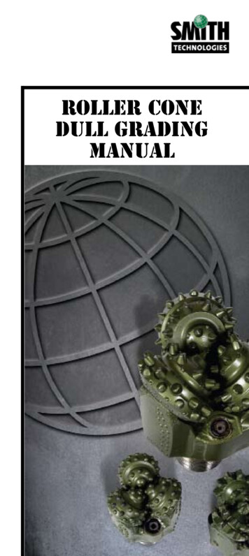
SYSTEM STRUCTUREIADC DULL GRADING SYSTEM CHARTCutting risticsReasonPulledXWorn Cutter (WT), Round TSPWorn Cutter (WT), MosaicWorn Cutter (WT), Round TSPBroken Cutter (BT), Round TSPBroken Cutter (BT),Natural DiamondWorn Cutter (WT), Triangular TSPBroken Cutter (BT), Triangular TSPBroken Cutter (BT), Triangular TSP
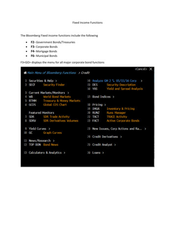
IADC DULL GRADING SYSTEM CHARTCutting risticsReasonPulledXCored PDC Bit (CR)Ring Out (RO) on a PDC BitJunk Damage (JD), PDC BitBalled Up (BU), Impregnated BitRing Out (RO) on a TSP BitErosion (ER) on a PDC Bit
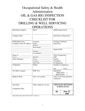
SYSTEM STRUCTUREIADC DULL GRADING SYSTEM CHARTCutting risticsXWorn Cutter (WT), PDCChipped Cutter (CT), PDCLost Cutter (LT), PDCChipped Cutter (CT), PDCWorn Cutter (WT), PDCHeat Checking (HC), PDCErosion (ER), PDCReasonPulled
LocationThe “Location” space is used to indicate the location of the primary“Dull Characteristics” noted in thethird space. Four possible fixedcutter bit profiles are shown inFigure 3, along with the codes usedto identify commonly referred tolocations on the bit. One or moreof these codes are used to indicatethe location of the dull characteristic(s) noted.IADC DULL GRADING SYSTEM CHARTCutting ringSealsGauge1/16”XFIGURE 3. FIXED CUTTER BIT PROFILESBearing SealsThis space is used only for rollercone bits. Therefore, it will alwaysbe marked “X” when grading fixedcutter bits.GaugeThe “Gauge (G)” space is used to record the condition of the bit gauge.Record an “I” here if the bit is still ingauge. Otherwise, the amount thebit is undergauge is recorded to thenearest 1/16”. For specific undergaugemarkings, see Figure 4.LocationBFIGURE 4. GAUGE CONDITIONCodeIExplanationIn Gauge1/16Undergaugeup to 1/16”2/16Undergauge1/16” to 1/8”3/16Undergauge1/8” to 3/16”4/16Undergauge3/16” to 1/4”RemarksOtherCharacteristicsReasonPulled
SYSTEM STRUCTUREReasons PulledThe last space on the IADC DullGrading System Chart is used torecord the reason the bit was pulled.A list of codes is shown below inTable 2.IADC DULL GRADING SYSTEM CHARTCutting tionBGBearingSealsGauge1/16”XTABLE 2. REASONS FOR PULLING BITBHA - Change BottomholeAssemblyDMF- Downhole Motor FailureDSF - Drillstring FailureDST - Drill Stem TestDTF - Downhole Tool FailureLOG - Run LogsRIG - Rig RepairCM - Condition MudCP - Core PointDP - Drill PlugFM - Formation ChangeHP - Hole ProblemsHR - HoursPP - Pump PressurePR - Penetration RateTD - Total Depth/CSG DepthTQ - TorqueTW - Twist OffWC - Weather ConditionsWO - Washout DrillstringRemarksOtherCharacteristicsReasonPulled
DULL GRADING WORN BITSThe following examples show howto apply the IADC Fixed Cutter DullGrading System to worn bits.IADC DULL GRADING SYSTEM CHARTCutting StructureInnerRowsExample sGauge1/16”XThis S279 was used to drill a veryhard and abrasive sandstone formation in the Rotliegendes in NorthernGermany. The special feature on thisbit is its Core Ejector (CE).It drilled 100 meters in 51 hourson a 4 3/4” Mach 2 downhole motorat an average ROP of 2.0 m/hr, andwas pulled at 4750 meters to changethe BHA.After pulling the bit, a uniformwear pattern was observed withthe exception of the beginning of aring out on the bit shoulder. Eightwaterways were plugged with formation, which did not slow downthe penetration rate. The bit wasstill in gauge.BIT INFORMATIONStyle: S279CESize: 5.875”TFA: 0.5BIT INFORMATIONPulled BitRemarksOtherCharacteristicsReasonPulled
DULL GRADING WORN BITSIADC DULL GRADING SYSTEM CHARTCutting StructureExample 2This R437GN was run in a horizontaldrilling operation. The first run wasin shale on a 6 3/4” Mach 1 fixedangle-build motor.The bit drilled 118 meters in8.5 hours and was pulled at 1433meters. The ROP was 13.9 m/hr.After the bit was pulled, no obvious wear could be seen, resultingin the IADC grading shown above.The bit was re-run on anotherwell in the same field in the sameformation, drilling 218 meters in13.5 hours for an average ROP of16.2 m/hrs.The bit was pulled when thebottomhole assembly had to bechanged.When dull grading the bit, littlewear on the cutting structure wasseen, resulting in a dull gradingof 1 for “inner / outer rows”. Threecutters were lost due to matrixerosion from a high flow rate, asshown in the “Dull” and “OtherCharacteristics” columns. The bitwas still in gauge, as indicated by“I” in the “Gauge” sticsReasonPulledXDull grading for the rerun bit.IADC DULL GRADING SYSTEM CHARTCutting risticsReasonPulledXBIT INFORMATIONStyle: R437GNSize: 8.5”TFA: 0.6IADC DULL GRADING SYSTEM CHARTCutting StructureExample 3This R437GN was run in a horizontalwell to drill brittle to plastic shaleand sandstone. It drilled 387 metersin 29.5 hours with an average ROPof 13.1 m/hr on a Mach 1 AdjustableKick Off Motor. The bit was pulledat 1820 meters because of slowpenetration sticsReasonPulled
Upon pulling the bit, it became obvious why the bit had ceased drilling— it was cored out and had lost allfour nozzles. The remaining cuttersdid not show any significant wear.NOTE: Although the bit lost all fournozzles, the primary “Dull Characteristic”is “cored” because this is the main reasonthe nozzles were lost. Lost nozzles arerecorded under “Other Characteristics”.BIT INFORMATIONStyle: R437GNSize: 8.5”TFA: 0.6IADC DULL GRADING SYSTEM CHARTCutting StructureExample 4This S725 BallaSet bit with cylindrical TSPs was used to drill claystoneand sand in the medium hard anddense Rotliegendes formation inHolland. It drilled 154 meters in 57hours, achieving an ROP of 2.7 m/hron a Mach 2 downhole motor in adirectional well. The bit was pulleddue to a slow rate of penetration.Dull grading indicated the cutterswere worn 75% and 100% on theinner and outer rows, respectively.In addition, a ring out can be seen inthe taper area. The bit was also 1/16”undergauge due to abrasivesands in the ationBGBearingSealsGauge1/16”XBIT INFORMATIONStyle: S725GNSize: 8.38”TFA: 0.10RemarksOtherCharacteristicsReasonPulled
DULL GRADING WORN BITSIADC DULL GRADING SYSTEM CHARTCutting StructureExample 5This R435SG was run four times inthe North Sea area. The bit drilleda total of 977 meters in 166.3 hours,mainly in salt/anhydrite formationsof the Zechstein. Three of the fourruns were on a Mach 1 DTU motorwith RPMs of 210 to 320.Dull grading of the first two runsshows no visible cutting structurefailure. The “Reason Pulled” wasDownhole Tool Failure (DTF) in bothcases. After the third run (389 metersin 89.5 hours ), the bit was pulled dueto BHA prob-lems, and showed auniform wear pattern of 520% wearfor the inner and outer rows. Whenpulled after run four, the cuttingstructure wear was 50% and 60% forthe inner and outer rows, respectively. After four runs, the bit alsoshowed some severe erosion and lostcutters in the taper area. (See phototaken after run 4)Practical Applications.The IADC Dull Grading Systemcan be used for multiple purposes.Manufacturers evaluate bit designand bit application. Operators evaluate and improve their drilling programs. The system can be computerized to build up a worldwide database in order to coordinate bitapplications.The main objective of the dullgrading system is to draw a “standardization picture” of a bit, regardlessof where, or under what circumstances the bit may have been used.This standardization is expectedto lead to better bit application anddesign throughout the industry.References:SPE/IADC Papers 16142, 16145 and nBGBearingSealsGauge1/16”XRun 2XRun 3XRun 4XBIT INFORMATIONStyle: R435SGSize: 12.25”TFA: 0.65 - 1.60RemarksOtherCharacteristicsReasonPulled
1996 Hughes Christensen Company. The emblems,and Hughes, Christensen, Eggbeater, Kingcutter and BallaSet are registeredtrademarks of Hughes Christensen Company. Black Ice, CSE, ECP, Mosaic, and SEC are trademarks of Hughes Christensen Company. Printed in U.S.A.WL / 6M US / 4M A4 / 6-96
PDC cutter wear is measured in a linear scale from one to eight across the diamond table, regardless of the cutter shape, size, type or exposure. Figure 1 illustrates the cutter wear grading system schematically. SYSTEM STRUCTURE FIGURE 1 INNER AREA 2/3 RADIUS OUTER AREA 1/3 RADIUS When grading a dull bit, the average amount of wear for each