Transcription
IADCDull Gradingfor PDC Drill BitsSPE/IADC 23939“First Revision to the IADC Fixed Cutter DullGrading System” 1992Version 2.4
How is Dull Grading Useful? Quick and simple way to describe the dull condition inan internationally recognized format A picture is worth a 1,000 words However, no bit photos are in the daily drilling report Identifies issues and improves future bit selection Bit balling Abrasive formation Cutter impact and vibrations Lighter or heavier set drill bit PDC vs Roller Cone
IADC Dull Grading – 8 BoxesEight boxes capture the dull bit condition and reason pulled:Cutting StructureInner Rows AverageCutter WearOuter Rows AverageCutter WearPrimary DullCharacteristicLocation ofPrimary DullCharacteristicBearingGaugeBearing &SealsUndersize16th’s inchRemarksOther DullCharacteristicThe SPE/IADC Fixed cutter dull grading document was last updated in1992. Since then, the industry has adapted new, unofficial codes toovercome some the short falls in the document.The SPE/IADC 1992 Roller cone & Fix cutter IADC dull grade documentsuse the same format and codes.ReasonPulled
Dull Grade SummaryCutting StructureInner Rows Average CutterWearOuter Rows –Average CutterWearAverage wearon inner 2/3rd’sof the diameterAverage wearon outer 1/3rdof the diameterValue: 0-8Value: 0-80:1:2:3:4:5:6:7:8:0:1:2:3:4:5:6:7:8:0% Wear1/8 Wear2/8 Wear3/8 Wear4/8 Wear5/8 Wear6/8 Wear7/8 Wear100% Wear1/2 of4 the cutterdiameter 50%wear4/8 0% Wear1/8 Wear2/8 Wear3/8 Wear4/8 Wear5/8 Wear6/8 Wear7/8 Wear100% WearPrimary DullCharacteristicBFBTCTERFCHCLTNORGWTBond FailureBroken CutterChipped CutterErosionFlat Crested WearHeat CheckingLost CutterNo CharacteristicsRounded GaugeWorn CuttersLocation ofPrimary /4 of2 the cutterdiameter 25%wear*Box is only usedfor cutter dullcharacteristicGaugeBearing &SealsUndersize(16th‘s inch)X – Usedfor allfixedcutter bitsI In-Gauge1 1/16”2 2/16”3 3/16” 16 16/16”RemarksOther DullCharacteristicBUCRJDLNNRPNRORRWOBalled UpCoredJunk DamageLost NozzleNot RerunnablePlugged NozzleRing OutRerunnableWash outSee also:“Primary DullCharacteristics”2/8 *Gauge Cuttersare pre-groundduring themanufacturingprocess.Bearing*More than oneLocation can benoted“I” can bemistakenfor “1”.Primary & OtherCharacteristics usedfor Roller Cone bits:“0” and“IN” areunofficiallyused.BC - Broken ConeCC - Cracked ConeCD - Cone DragCI - Cone InterferenceLC - Lost ConeOC - Off Center WearPB - Pinched BitSD - Shirttail damageSS - Self SharpeningWearTR - TrackingMeasuredwith a “NoGo” PDCGauge RingReason PulledBHA Changed Bottom HoleAssemblyDMF Downhole MotorFailureDSF Drill String FailureDST Drill Stem TestDTF Downhole ToolFailureLOG Run LogsRIG Rig RepairCM Condition MudCP Core PointDP Drill PlugFM Formation ChangeHP Hole ProblemsPP Pump PressurePR Penetration RateTD Total DepthTQ TorqueTW Twist-OffWC Weather ConditionsWO Washout Drill String
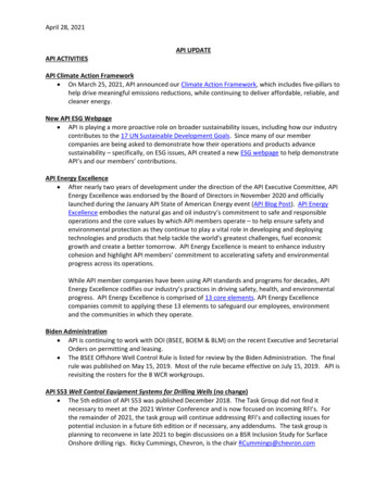
Inner & Outer Row: LocationCutting StructureInner Rows(Inner 2/3rd’s)Outer Rows(Outer 1/3rd)Average CutterWear(0-8)Average CutterWear(0-8)Primary DullCharacteristicLocation ofPrimary DullCharacteristicBearingGaugeBearing SealsUndersize(16th’s inch)RemarksOther DullCharacteristicReason PulledThe average wear in the inner & outerrows are calculated and recorded in thefirst two boxes.Inner 2/3rd’s of thebit diameterGauge cutters are excluded from thewear in the outer rowsOuter 1/3rd of thebit diameter
Tip: Inner & Outer Row: LocationThe highest cutter on each blade isthe approximate transition betweenthe Inner 2/3rd’s & Outer 1/3rdOuter 1/3rdInner 2/3rd’s
Inner & Outer: Cutter Wear (0-8)Cutting StructureInner Rows(Inner 2/3rd’s)Outer Rows(Outer 1/3rd)Average CutterWearAverage CutterWearGrade: 0-8Grade: 0-8Location ofPrimary DullCharacteristicPrimary DullCharacteristicBearingGaugeBearing SealsUndersize(16th’s inch)RemarksOther DullCharacteristicReason PulledA grading scale between 0-8 is used to note the amount of wear in the Inner & Outer rowsGrade012345678Wear0/81/82/83/84/85/86/87/88/8
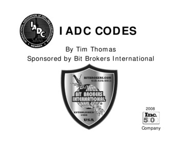
Inner & Outer: Cutter Wear (0-8)Cutting StructureInner Rows(Inner 2/3rd’s)Outer Rows(Outer 1/3rd)23Primary DullCharacteristicLocation ofPrimary DullCharacteristicBearingGaugeBearing SealsUndersize(16th’s inch)RemarksOther DullCharacteristicReason PulledCalculating Average Cutter Wear for Inner & Outer Rows1) Grade each cutter with a 0 to 82) Add up the values3) Divide by the number of cutters4) Round to the nearest numberInner 2/3rd’s0123 3Example for only 1 bladeOuter 1/3rd34Example for only one BladeInner 2/3rd’s Row0 1 2 3 3 99 / 5 1.8 (round up)Inner 2/3rd’s Wear “2”32GaugeCutter(Not Included)Outer 1/3rd Row3 4 3 2 1212 / 4 3Outer 1/3rd Wear “3”
Tip: Inner & Outer: Cutter Wear The wear value (0-8) is the average wear condition, not the maximumamount of wear on one cutter. What is the minimum and maximum cutter wear? The average will be between the minimum and maximum values Is it closer to the minimum or maximum value? Establish the “4” cutter center line, 50% wear condition.Then estimate “2”, 25% wear condition.Does the cutter wear look closer to “1”, “2” or “3”. (See below)4Step 1)Establish the center line, “4”24Step 2)Estimate “2”, 50% fromcenter line to cutter tip1234Step 3)Is the wear closer to “1”,“2” or “3”?
Tip: Inner & Outer: Cutter Wear Cutters with no wear are oftenincorrectly graded 1-1 to indicatethe bit is used. 0-0 is the correct grading Gauge, Gauge Pad & Up Drillcutters are not included in theGaugeOuter Row cutter wear calculation.GaugePadUp Drill
Tip: Inner & Outer: Cutter Wear Secondary row cutters are includedin the Average Cutter Wearcalculation.“0”Double Row Cutter Cutter wear is measured across thediamond table and not the carbidesubstrate. If the diamond is missingand the carbide is intact, the cutter isgraded as an “8”.DL - Delaminated Cutter (Non-IADC)“1”
Tip: Inner & Outer: Cutter WearWhen the cutter is irregularlybroken, estimate the amount ofdiamond remainingFullDiameterGrade: “3”
Dull Characteristic: PrimaryCutting StructureInner Rows Average CutterWearOuter Rows –Average CutterWearPrimary DullCharacteristicLocation ofPrimary DullCharacteristicBearingGaugeBearing &SealsUndersize(16th’s inch)RemarksOther DullCharacteristicReason PulledWhat is the mostnotable cuttercondition?CutterBFBTCTERFCHCLTNORGWTBond FailureBroken CutterChipped CutterErosionFlat Crested WearHeat CheckingLost CutterNo CharacteristicRounded GaugeWorn CuttersDLSPUnofficial:DelaminationSpalled cutterSPE 23939 – Dull Characteristics – “The mostprominent or “primary” physical change from newcondition of the cutter is recorded in the 3rd box.“Other” dull characteristics of the bit are noted inthe 7th box. The difference being that 3rd boxdescribes cutter wear, while the 7th box mayconcern other wear characteristics of the bit as awhole.”
Dull Characteristic: PrimaryCutterNo No CharacteristicCutters are in new condition with no notable dull characteristics
Dull Characteristic: PrimaryCutterERErosionErosion of the carbide substrate
Dull Characteristic: PrimaryCutterFCFlat Crested WearSmooth, flat wear across the diamond andpossibly the carbide substrateFC – Flat Crested Wear can be classified as WT – Worn Cutter.However, FC - Flat Crested Wear is suggested when wear issmooth and flat.Gauge cutters are manufactured with cutter grind and shouldnot be graded FC – Flat Crested WearGauge Cutter, asper manufactured
Dull Characteristic: PrimaryCutterCTChipped CutterChipping on the diamond edgeChipping does do not extend into the carbide substrate (Non-IADC)
Dull Characteristic: PrimaryCutterBTBroken CutterFracture damage through the diamondtable and into the carbide substrate.BT - IADCBT - IADC
Dull Characteristic: PrimaryCutterWT Worn CuttersWT – Worn Cutters is non-planar wearor the combination of the following:CTBTERFCChipped CutterBroken CutterErosionFlat Crested WearNon-planer wear flatNon-planer wear flatNon-planer wear flat
Dull Characteristic: PrimaryCutterCutterCutterCutterCT – Chipped CutterBT – Broken CutterFC – Flat Crested WearWT – Worn CutterDiamond Edge ChippingFracture through thecarbide substrateFlat, Smooth WearNon Planar Wear or acombination of CT, BT, FC, ER
Dull Characteristic: PrimaryCutterHC Heat CheckingCracks on the carbidesubstrate Cylindrical body Wear flat
Dull Characteristic: PrimaryCutterLTLost CutterMissing cutter
Dull Characteristic: PrimaryCutterBFBond FailureSeparation between two carbide substrate pieces.BF – Bond Failure can also be used to describe SP - Spalling (Non-IADC) DL - Delamination (Non-IADC)LC – Lost Cutter: 100% loss of the carbide substrate and diamond
Dull Characteristic: PrimaryCutterCutterCutterBF - Bond Failure (IADC)SP - Spalling (Non IADC)DL - Delamination (Non IADC)Separation betweenSubstrate & SubstrateSeparation betweenDiamond & DiamondSeparation betweenDiamond & Substrate
Dull Characteristic: PrimaryCutterRG Rounded GaugeHigh amount of diamond lossin the upper shoulder togauge transition.The bit can be in-gauge orsignificantly under-gauge.Shoulder toGauge transition
Tip: Dull Characteristic Box 3 is dedicated for “Cutter” information. If there are no cutter dull characteristic, then indicate “NO”. If there are many notable characteristics on the bit, pickthe one that hindered performance or caused the bit to bepulled out of hole. For example: WT and not HC Only one cutter characteristic code in Box 3 Non-IADC practices: Multiple codes in one box. Ie. BT/HC DL – Cutter Delamination, separation at the diamond-carbidesubstrate interface. SP – Cutter Spalling, thin layers of diamond separated from thecutter face.
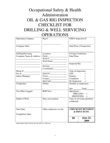
Location of Primary Dull CharacteristicCutting StructureInner Rows(Average CutterWear)Outer Rows(Average CutterWear)Primary DullCharacteristicLocation ofPrimary DullCharacteristicBearingGaugeBearing &SealsUndersize(16th’s inch)RemarksOther DullCharacteristicReason PulledC, N, S, T, G, ALocation ofPrimary AllMore than one Locationcan be notedG: GaugeS: Shoulder – CurvedT: Taper - StraightC: ConeN: NoseSPE 23939 – Location – “Used to indicate the location ofthe primary dull characteristic, 3rd box. One or more ofthese codes may be used to indicate the location.”
Tip: Location of Primary Dull “S” Shoulder – Rounded shoulder profiles are commonly used on PDC bits. “T” Taper – Flat taper profiles are not commonly used on PDC bits. Shoulder & Taper - The combination of a curved shoulder and flat taperprofile is extremely uncommon on PDC bits. Historically used on naturaldiamond and TSP products with long profiles.S: Shoulder – Curved (shown)T: Taper - Straight
Bearing & SealsCutting StructureInner Rows(Average CutterWear)Outer Rows(Average CutterWear)Primary DullCharacteristicLocation ofPrimary DullCharacteristicBearingGaugeBearing &SealsUndersize(16th’s inch)RemarksOther DullCharacteristicXFixed Cutter BitRoller Cone BitSPE 23939 – Bearing– “This box is used only for roller conebits. It will always be marked “X” for fixed cutter bitsReason Pulled
Gauge UndersizeCutting StructureInner Rows(Average CutterWear)Outer Rows(Average CutterWear)Primary DullCharacteristicLocation ofPrimary DullCharacteristicBearingGaugeBearing &SealsGaugeUndersizeRemarksOther DullCharacteristicReason Pulled# 16th InchGauge UndersizeI12348 In Gauge1/16th undersize2/16th undersize3/16th undersize4/16th undersize8/16th undersize 1 ½” 24/16” “24”Procedure:1) Use a “No-Go PDC” gauge ring2) Place the gauge ring over thelargest diameter: PDC cutter orGauge Pad3) Pull the ring tight to one side4) Measure the opposing size5) Record the distance to thenearest 1/16th of an inchSPE 23939 – Gauge – “6th Box isused to record the condition of thebit gauge. “I” is used for the bit stillin gauge. Otherwise, the amountthe bit is under gauge is recordedto the nearest 1/16th of an inch”Procedure:PullNo-Go PDCGauge Ring2/16” “2”
Tip: Gauge UndersizeGauge cutters are pre-ground during themanufacturing process. The amount of gaugecutter grind can vary by company and product line.
Tip: Gauge UndersizeThe gauge pad might be tapered orstepped. Thus, measure the largestdiameter, typically the gauge cutters.LargestDiameterStep Gauge1-2mm undersizeLargestDiameter?
Tip: Gauge Undersize “I” In-Gauge is commonly mistaken as “1”, 1/16th. Unofficially, “0” or “IN” are used in place of “I”. Use a “No-Go” gauge ring when dull grading PDC & Roller cones bits. “No-Go” gauge ring: Measures minimum OD tolerance. “Go” gauge ring: Measures maximum OD tolerance. PDC and Roller cone bits use different gauge rings.It is not suggested to use PDC & Roller cone rings interchangeably. PDC Bit tolerance: 0.000” to slightly undersized. Roller Cone Bit tolerance: -0.000” to slightly oversized.PDC & Fix Cutter BitDiameter RangeDiameter Tolerance(mm)Diameter Tolerance(inch)Up to and including 6 ¾” 0.00 / -0.38 0.000 / -0.015 6 ¾” and 9” 0.00 / -0.51 0.000 / -0.020 9” and 13 ¾” 0.00 / -0.76 0.000 / 0.030 13 ¾” and 17 ½” 0.00 / -1.14 0.000 / 0.045 17 ½” 0.00 / -1.60 0.000 / 0.063
Dull Characteristic: OtherCutting StructureInner Rows(Average CutterWear)Outer Rows(Average CutterWear)Primary DullCharacteristicLocation ofPrimary DullCharacteristicBearingGaugeBearing &SealsUndersize(16th’s inch)RemarksOther DullCharacteristicReason PulledWhat is the secondmost notablecondition?Cutter & Bit Body(Only the cutter dullcondition)Other Dull CharacteristicBit BodyCutterBFBTCTERFCHCLTNORGWTBond FailureBroken CutterChipped CutterErosionFlat Crested WearHeat CheckingLost CutterNo CharacteristicRounded GaugeWorn CuttersDLSPUnofficial:DelaminationSpalled cutterCRERHCJDROWOCoredErosionHeat CheckingJunk DamageRing OutWash OutBBUnofficialBroken BladeHydraulicBU Balled UpLN Lost NozzlePN Plugged NozzleGeneralNR Not RerunnableRR RerunnableNO No Characteris
“S” Shoulder – Rounded shoulder profiles are commonly used on PDC bits. “T” Taper – Flat taper profiles are not commonly used on PDC bits. Shoulder & Taper - The combination of a curved shoulder and flat taper profile is extremely uncommon on PDC bits. Historically used on natural diamond and TSP products with long profiles.