Transcription
3700 SERIES USER MANUALProgrammable DC Electronic Load3700 SERIESuser manualC O N TE N TSCAUTION.1SAFETY NOTES.1Chapter 1 General Introduction.21.1 General Introduction.21.2 Specification.21.3 Features.31.4 Dimension and Structure.31.4.1 Dimension.31.4.2 Structure.41.4.2.1 Front view.41.4.2.2 Back view.5Chapter 2 Operation.62.1 General Operation.62.2 Function Introduction.62.2.1. Main functions.62.2.2 Sub-functions.62.3 The Operation of the Functions.62.3.1 I-set.72.3.2 P-set.82.3.3 R-set.82.3.4 Store Data Function.92.3.5 Recall Data Function.102.3.6 Switch ON/OFF of power output.103700 Series Programmable DC Electronic LoadVERSION 1.0 2003.12.3.7 The function of the Menu.102.3.7.1 Set up the Limit Current.112.3.7.2 Set up the Limit Power.112.3.7.3 Program Set.112.3.7.4 Set up the Communication.172.3.7.5 Set up Communication Address (0 254).172.3.7.6 Set up Locking Keyboard.182.3.7.7 Set up SAVE OPTION.182.3.7.8 EXIT Function.18ElectronicLoad SoftwareChapter 1 System Installation.201.1 Installation.201.2 Start the System.221.3 Uninstall the System.24Chapter 2 Functions Introduction.252.1 COM Port Set Interface.252.2 The Current Limit and the Power Limit Set.262.3 The Current Value, the Power Value and theResistance Value Setup.262.4 Programming Setting Interface.272.5 The Explanation to the Receiving Zone.28Chapter 3 Maintenance and Service.2930
3700 SERIES USER MANUALCAUTIONBefore switching on the DC Electronic load, the protective earth terminal of this instrument must be connected to the protective conductor of the AC line power cord. The AC lineplug shall be inserted only in a socket outlet provided with a negated by the use of an extensioncord (or power cable) without a protective grounding conductor.SAFETY NOTESThe following general safety precautions must be observed during all phases of operation,service, and repair of this instrument. Failure to comply with these precautions or withspecific warnings elsewhere in this manual violates safety standards of design, manufacture,and intended use of the instrument. The Manufacturer assumes no liability for the customer’sfailure to comply with these requirements.Ground the InstrumentThis product is provided with a protective earth terminal. To minimize shock hazard,the instrument chassis and cabinet mush be connected to an electrical ground. The in strumentmust be connected to the AC Electronic Load mains through a three-conductor power cable,with the third wire firmly connected to an electrical ground (safety ground) at the poweroutlet. For instruments designed to be hard-wired to the AC power lines (supply mains),connect the protective earth terminal to a protective conductor before any other connection ismade. Any interruption of the protective (grounding) conductor or discon nection of theprotective earth terminal will cause a potential shock hazard that could result in personalinjury. If the instrument is to be energized via an external autotransformer for voltage reduction,be certain that the autotransformer common ter minal is connected to the neutral (earthed pole)of the AC power lines (supply mains).Keep Away From Live CircuitsOperating personnel must not remove instrument covers. Component replacement andinternal adjustments must be made by qualified service personnel. Do not components withpower cable connected. Under certain conditions, dangerous voltages may exist even with thepower cable removed. To avoid injuries, always disconnect power, discharge circuits andremove external voltage sources before touching components. Do Not Substitute Parts orModify Instrument Because of the danger of introduction additional hazards, do not installsubstitute parts or perform any unauthorized modification to the instrument. Return theinstrument to a qualified dealer for service and repair to ensure that safety features are maintained.3700 Series Programmable DC Electronic LoadVERSION 1.0 2003.11
3700 SERIES USER MANUALChapter 1 General Introduction1.1 General Introduction3700 Series Programmable DC Electronic Load is a kind of mini-size DC programmableelectronic load with nice appearance. Also it is equipped with back-light LCD display, numberkeypad and rotary code switch which let it much easier to use. Voltage, current and power canall be displayed on the LCD or computer and tableau is distinct and clear. It can be operated atcon stant current mode, constant resistance mode and constant power mode. It is an essentialin-strument for scientific research, education, laboratory, test, service and so on institutions.1.2 SpecificationType3710A3711AInput quantity11Input voltageDCInput current0 30A0 30AInput power0 150W0 300WVoltage resolutionCurrent resolutionLowest Conductiue Resistance0 360VDC0 360V0.000-3.999 (0.2% 3mV) 4.00-35.999 (0.2% 30mV) 36.0-360.0V (0.3% 300mV)0.000-2.999 (0.2% 3mA)3.00-30.00(0.2% 30mA) 0.08Ripple 10mVppCommunicationRS232/RS485 *Monitor softwareFree software VC / VB / DELPHI / LABVIEW / COM partsMemory10 points EEPROMProtective modeOver voltage/over current/over power/over heat/polarity-reversing connectionPower voltageAC 110/220 available (60/50HZ)Weight5.0KgAccessoriesSoftware, users manual, AC power cable, handlebarsCommunication cable for RS232PurchaseOption PartsCommunication cable for RS485Mounting rack3700 Series Programmable DC Electronic LoadVERSION 1.0 2003.12
3700 SERIES USER MANUAL1.3 Features1. LCD display with back light.2. Number keypad.3. High resolution at 1mV.4. Protection for over current.5. Protection for over power.6. Adjustable constant resistance, constant current and constant power output.7. Can be set by number key or rotary code switch.8. Power shut-down memory function9. Monitored by PC software.10. Mini-size and light weight.11. Can be used in parallel connection.12. Programmable output.1.4 Dimension and Structure1.4.1 DimensionFig 1 Dimension of 3700 Series Programmable DC electronic load3700 Series Programmable DC Electronic LoadVERSION 1.0 2003.13
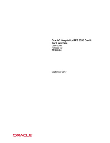
3700 SERIES USER MANUAL1.4.2 Structure1.4.2.1 Front viewFront panel is for users to operate, andthere is one LCD display, one numberkeypad and one rotary keypad. Pleasesee the following picture.Fig2. Front view of 3700 Series DC electronic load1. LCD display0.000A0.000VOF0.0W0.000AISThe upper line:The real current value,voltage value and output statusFig3. LCD Display of 3700 Series electronic load(ON/OFF represent power source output status)The lower line:The output power rated value.IS (PS, RS, SW) represents constant current,constant power, constant resistance and program output.2. Arrangement of the KeyboardIn common state, the keyboard will execute0 9: The number keysthe prompting functions of the black words.And in special mode, it will change into thefunctions of the orange color words.Out ON/OFF: Switch ON/OFF the outputStore: Save the current setting valueR-set: Set up constant resistance valueSTART: Begin to program outputI-set: Set up constant current valueSTOP: Stop to program outputP-set: Set up constant power valueRecall: Read the saved setting valueFig4. Key board of 3700 Series DC electronic loadMenu: Menu function operation: The up moving key: The down moving keyV/A: Represent V at the voltage mode, representA at the current mode.mV/ mA : Represent mV at the voltage mode, andrepresent mA at the current mode.3700 Series Programmable DC Electronic LoadVERSION 1.0 2003.14
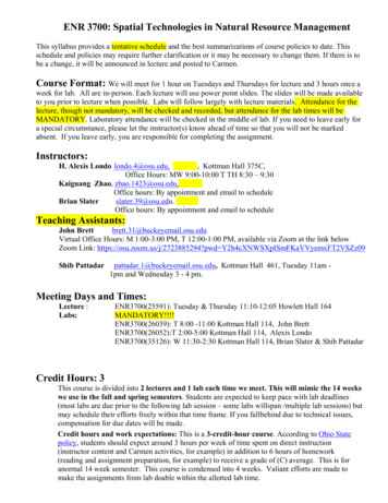
3700 SERIES USER MANUAL3. Rotary code switch and function keysÄ: The left moving keyº%: The right moving keyESC: Can be used to exit any working stateOK: Confirmation keyRotary SW: The rotation keyFig5. Rotary and function keys1.4.2.2 Back viewPC connectioninterfaceWire rackfan wrapPower supply plugFuseChange over SwitchFig6. Back viewThe fuse can be changed easily by using a small screw driver. Please use a fuse within therange of 0.3-0.5A.3700 Series Programmable DC Electronic LoadVERSION 1.0 2003.15
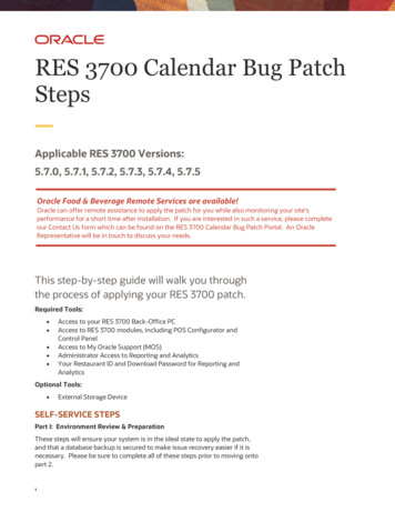
3700 SERIES USER MANUALChapter 2 Operation2.1 General operation1. Connect the electronic load with PC3311 Cable3700 Series electronic loadFig 2.1 Connect the electronic load with PC2.2 Function introduction2.2.1. Main functions1. Set up a constant current output2. Set up a constant power output4. Set up a constant resistance output5. Store 10 sets of date which had been set up6. Recall the stored data7. Start/Stop8. Switch ON/OFF the electronic load output2.2.2 Sub-functions1. Set up maximum current2. Set up maximum power3. Set up the programming4. Set up the communication5. Set up password2.3 The operation of the functionWe know that there are 8 main functions and 5 sub-functions of this electronic load, the followingwill descript how to operate all of the functions. Before any operation, please connect the power, andswitch the power on, then the power indicator will be lighted.3700 Series Programmable DC Electronic LoadVERSION 1.0 2003.16
3700 SERIES USER MANUAL2.3.1 I-set (set up a constant current )Set up a constant DC current output is the first main function of programmable DC electronic load,3710A electronic load provides two methods to set up the constant DC cur rent output by using thenumber keyboard and the rotary button. Please see the following operation procedure.ProcedureStep 1Operation detailsLCD displayPress “ I-set ”SET CURR 0.00ANEW Step 2Enter the password ( Or jump to step 4 if theENTER PASWORDkeyboard is unlocked)Step 3Press “ OK ” button ( it will return to step 2 if yourENTER PASWORDpassword is wrong for reentering)Step 4Press “ I-set ” to enter the original value which displayedSET CURR 2.00Aon the LCD, or enter a new value by using the numberNEW key or rotate “ Rotary SW ” to adjust the voltage valueand then press the “ I-set ” button for confirmationIt will exit the setting up voltage operation at any procedure by press ESC buttonFor example, how to set up the output current at 3.12A1. To set up by using number keyboardStep1. Press “ I-set ” button,Step2. Enter the password by using the number keyboard (if the keyboard is unlocked, please do step4),Step3. Press “ OK ” button (if the password is wrong, please do step2 for reentering),Step4. Press “ 3 ”, “ . ”, “ 1 ” and “ 2 ” button to enter the voltage value,Step5. Press “ I-set ” button to confirm the voltage value.2. To set up by using Rotary SW(1) If the key board is unlocked by password, directly rotate the “ Rotary SW ” button, andvoltage willbe continually changed from the previews value according the rotation. At the beginning, the cursor willbe shown on the last number of the value which is indicated on the LCD, you can move the cursor to thefirst number, second number etc by using “” and“” buttons, and then rotate to change each number, and let it stay at 3.12 A. Please see the following figures. Then press “ I-set ” to confirm the value.0.000A 0.000V OF0.0W3700 Series Programmable DC Electronic LoadVERSION 1.0 2003.13.12A IS7
3700 SERIES USER MANUAL(2) If the keyboard is locked by passwordStep1. Press “ V-set ” button,Step2. Enter the password by using the number keyboardStep3. Press Enter button (if the password is wrong, please do step2 for reentering),Step4. Rotate the Rotary SW button to change the value, the operation is as the same as item (1)Step5. Press “ I-set ” button to confirm the current value.2.3.2 P-set (set up a constant power)3700 Series electronic load can be set up for a constant power .Constant power setup procedure is as following:ProcedureStep 1Operation detailsLCD displaySET POWER 30.0WPress “ P-set ”NEW Step 2Enter the password ( Or jump to step 4 if theENTER PASWORDkeyboard is unlocked)Step 3Press “ OK ” button ( it will return to step 2ENTER PASWORDif your password is wrong for reentering)Step 4Press “ P-set ” to enter the original value whichSET POWER 30.0Wdisplayed on the LCD, or enter a new value byNEW 72.2using the number key or rotate “ Rotary SW ” toadjust the power value and then press the “ P-set ”button for confirmationIt will exit the setting up current operation at any procedure by press ESC button2.3.3 R-set (set up a constant resistance)3700 Series electronic load can be setup for a constant resistance.Constant resistance setup procedure is as following:ProcedureStep 1Operation detailsPress “ R-set ”LCD displaySET RISIS 200.0 NEW Step 2Enter the password ( Or jump to step 4 if the keyboardENTER PASWORDis unlocked)3700 Series Programmable DC Electronic LoadVERSION 1.0 2003.18
3700 SERIES USER MANUALStep 3Press “ OK ” button ( it will return to step 2 if yourENTER PASWORDpassword is wrong for reentering)Step 4Press “ R-set ” to enter the original value whichSET RISIS 200.0 displayed on the LCD, or enter a new value by using theNEW 50.0number key or rotate “ Rotary SW ” to adjust the powervalue and then press the “ R-set ” button for confirmationIt will exit the setting up current operation at any procedure by press ESC button2.3.4 Store data functionTo users, this is a good function for ease using. If you want to use current output, resistanceoutput and power output schedule as following in one hour, you can edit a program as the requirement, and then store it in the memory of 3700 Series DC electronic load as a number. When you needit, just recall it.Time scheduleConstant current output0 10 minute5A11 20 minute10A21 30 minute15A31-45 minute10A46 60 minute5AThe store operation always be done after editing a program schedule for current output, resistance output and power output, the operation is as following:ProcedureStep 1The operation MethodsPress “ Store ” buttonLCD display****V****AStep 2****W**Enter the set value for store number(from 1 to 10)by using the number key or rotate the rotary buttonSTORE 1to change the set value number for storeStep 3Press “ Store ” button to confirm the set value,if the number is out of the range from 1 to 10, it willSTORE *retune to Step 2 for reenterIt will exit the store operation at any procedure by press ESC button3700 Series Programmable DC Electronic LoadVERSION 1.0 2003.19
3700 SERIES USER MANUAL2.3.5 Recall data functionIn the last paragraph, we know that we can store 10 programs of the electronic load in the memory.Also you can recall any one program from the stored data. It means that you needn’t to set up again for theusually requirement, and it bring your much ease to use. The recall operation is as following.ProcedureThe operation MethodsStep 1LCD displayPress “ Recall ” button****V ****W****AStep 2**Enter the number of the set data which you want torecall (from 1 to 10) by using the number key or rotateRECALL 1the rotary button to change the number you want recallStep 3Press “ Enter ” button to confirm , if the number is outRECALL *of the range from 1 to 10, it will retune to Step 2 for reenterIt will exit the Recall operation at any procedure by press ESC button2.3.6 Switch ON/OFF power outputThe output of 3700 Series type electronic load should be off when it is powered, users can change theoutput status by using ON/OFF button. The button is a turn over button, when the original output is ON,press the button, then the output will be changed to OFF status, when the original output is OFF, pressthe button, then the output will be changed to ON status.2.3.7 The function of the Menu3700 Series electronic load provides a Menu operation for some special functions. The operation andfunction are as following.ProcedureThe operation MethodsLCD displayStep 1Press “ Menu ” buttonStep 2The LCD display the menu functions one by one,MAX CURRENT SETuser can use the UP and DOWN button to changeMAX POWER SETthe selecting each function, Press “ Enter ” buttonPROGRAM SETto execute the selected functionCOMMUNICATION SETADRESS SETSAVE OPTIONKEY LOCKEXITIt will exit the Menu operation at any procedure by press ESC button3700 Series Programmable DC Electronic LoadVERSION 1.0 2003.110
3700 SERIES USER MANUALThe menu operation includes MAX CURRENT SET, MAX POWER SET, PROGRAM SET,COMMUNICATION SET, ADDRESS SET, SAVE OPTION, KEY LOCK Function. We will descriptthe details as following.2.3.7.1 Set up the maximum currentWhen you select the MAX CURRENT SET function, the LCD will display :MAX CURR **** ANEW You can set the current value by using the number keyboardor rotating the ROTARY button. Then confirm the value bypressing “ OK ” button.2.3.7.2 Set up the maximum powerWhen you select the MAX POWER SET function, the LCD will display as:You can set the power value by using the number keyboardMAX POWE **** WNEW or rotating the ROTARY button. Then confirm the value bypressing “ OK ” button.2.3.7.3 Program SetWhen you select the PROGRAM SET, the LCD will display as:CURRENT OUTPOWE OUTUsers can set constant current, constant power and constantresistance format by using the up and down key or the rotarybutton, and then confirm it by pressing “ OK ” button. TheRESISTANCE OUTdetail procedure of setting up is as following.1. Set a program to provide a constant Current Output1) Select CURRENT OUT, press OK to confirm2) The LCD will displaySTEP NUMBER **NEW 33) Enter the step number, if you wan to set 3 steps, then enter 3, then press OK to confirm.(Please pay attention to the range of this value is from 1 to 11. Maximum is 11 steps).3700 Series Programmable DC Electronic LoadVERSION 1.0 2003.111
3700 SERIES USER MANUAL4) The LCD will displaySTEP 1 SET 0.00NEW 15) You need to enter a current value for the first step, (Please pay attention to the range of this valueof this type DC Load), such as 1 A, so you should enter 1, then press OK to confirm, and then the LCDwill displaySTEP 1 TIM 1SNEW 26) At this time, you need to enter a time value, (Please pay attention to the range of this time value isfrom 1 to 7200 seconds, maximum is 7200 seconds), such as 2 seconds, so you should enter 2, then pressOK to confirm, and then LCD will displaySTEP 2 SET 0.00NEW 27) At this time, you need to enter a current for the second step, (Please pay attention to the range of thiscurrent value), such as 2A, so you should enter 2, then press OK to confirm, and then LCD will displaySTEP 2 TIM 1SNEW 58) At this time, you need to enter a time value for the second step (the range of this time value is from1 to 7200 seconds), such as 5 seconds, so you should enter 5, then press OK to confirm, and the LCD willdisplaySTEP 3 0.00NEW 39) At this time, you need to enter a current for third step, such as 3A, so you should enter 3, thenpress OK to confirm, and then LCD will displaySTEP 3 TIM 1SNEW 103700 Series Programmable DC Electronic LoadVERSION 1.0 2003.112
3700 SERIES USER MANUAL10) At this time, you need to enter a time value for the third step, such as 10 seconds, so you shouldenter 10, then press OK to confirm, and the LCD will displayONE TIMEREPEAT11) At this time, if you select ONE TIME, and press OK to confirm, then the constant current will beprovided by this load at the following scheduleStep 1 1A for 2 secondsStep 2 2A for 5 secondsStep 3 3A for 10 secondsIf you select REPEAT, and press OK to confirm, then the constant currents schedule as the above willbe provided repeatedly.2. Set a program to provide a constant Power Output1) Select POWER OUT, press OK to confirm2) The LCD will displaySTEP NJUMBER 1NEW 33) Enter the step number, if you wan to set 3 steps, then enter 3, then press OK to confirm. (Please payattention to the range of this value is from 1 to 11. Maximum is 11 steps)4) The LCD will displaySTEP 1 SET 0.0NEW 505) You need to enter a power value for the first step, (Please pay attention to the range of this powervalue), such as 50W, so you should enter 50, then press OK to confirm, and then the LCD will display3700 Series Programmable DC Electronic LoadVERSION 1.0 2003.113
3700 SERIES USER MANUALSTEP 1 TIME 1SNEW 306) At this time, you need to enter a time value, (Please pay attention to the range of this time value isfrom 1 to 7200 seconds, maximum is 7200 seconds), such as 30 seconds, so you should enter 30, thenpress OK to confirm, and then LCD will displaySTEP 2 SET 0.0NEW 1007) At this time, you need to enter a power value for the second step, (Pay attention to the range of thispower value), such as 100W, so you should enter 100, then press OK to confirm, and then LCD willdisplaySTEP TIME 1SNEW 608) At this time, you need to enter a time value for the second step (the range of this time value is from1 to 7200 seconds), such as 60 seconds, so you should enter 60, then press OK to confirm, and the LCDwill displaySTEP 3 SET 0.0NEW 1509) At this time, you need to enter a power value for third step, such as 150W, so you should enter 150,then press OK to confirm, and then LCD will displaySTEP TIME 1SNEW 12010) At this time, you need to enter a time value for the third step, such as 120 seconds, so you shouldenter 120, then press OK to confirm, and the LCD will display3700 Series Programmable DC Electronic LoadVERSION 1.0 2003.114
3700 SERIES USER MANUALONE TIMEREPEAT11) At this time, if you select ONE TIME, and press OK to confirm, then the constant power will beprovided by this load at the following scheduleStep 1 50W for 30 secondsStep 2 100W for 60 secondsStep 3 150W for 120 secondsIf you select REPEAT, and press OK to confirm, then the constant currents schedule as the above willbe provided repeatedly.3) Set a program to provide a constant Resistance Output1) Select RESISTANCE OUT, press OK to confirm2) The LCD will displaySTEP NUMBER 1NEW 33) Enter the step number, if you want to set 3 steps, then enter 3, then press OK to confirm. (Please payattention to the range of this value is from 1 to 11. Maximum is 11 steps).4) The LCD will displaySTEP 1 SET 500.0NEW 1005) You need to enter a resistance value for the first step, (Please pay attention to the range of thisresistance value ), such as 100 , so you should enter 100, then press OK to confirm, and then the LCD willdisplaySTEP 1 TIM ****NEW 303700 Series Programmable DC Electronic LoadVERSION 1.0 2003.115
3700 SERIES USER MANUAL6) At this time, you need to enter a time value, (Please pay attention to the range of this time value isfrom 1 to 7200 seconds, maximum is 7200 seconds), such as 30 seconds, so you should enter 30, thenpress OK to confirm, and then LCD will displaySTEP 2 SET 500.0NEW 2007) At this time, you need to enter a resistance value for the second step, (Pay attention the range of thisvalue), such as 200 , so you should enter 200, then press OK to confirm, and then LCD will displaySTEP 2 TIME 1SNEW 608) At this time, you need to enter a time value for the second step (the range of this time value is from1 to 7200 seconds), such as 60 seconds, so you should enter 60, then press OK to confirm, and the LCDwill displaySTEP 3 SET 500.0NEW 3009) At this time, you need to enter a resistance value for third step, such as 300 , so you should enter300, then press OK to confirm, and then LCD will displaySTEP 3 TIME 1SNEW 12010) At this time, you need to enter a time value for the third step, such as 120 seconds, so you shouldenter 120, then press OK to confirm, and the LCD will displayONE TIMEREPEAT3700 Series Programmable DC Electronic LoadVERSION 1.0 2003.116
3700 SERIES USER MANUAL11) At this time, if you select ONE TIME, and press OK to confirm, then the constant power will beprovided by this load at the following scheduleStep 1 100 for 30 secondsStep 2 200 for 60 secondsStep 3 300 for 120 secondsIf you select REPEAT, and press OK to confirm, then the constant currents schedule as the abovewill be provided repeatedly.2.3.7.4 Set up the communicationThis function is for monitoring the output data of the electronic load by using a computer.When you select COMMUNICATION SET function, the LCD will display as:BUAD RATE 4800BUAD RATE 9600BUAD RATE 19200BUAD RATE 38400Users can change the communication setup by usingUP and DOWN keys or rotating the ROTARY button, andconfirm the value by pressing “ OK ” button.BUAD RATE 4800 represent BUAD rate 4800bpsBUAD RATE 9600 represent BUAD rate 9600bpsBUAD RATE 19200 represent BUAD rate 19200bpsBUAD RATE 38400 represent BUAD rate 38400bps2.3.7.5 Set up communication address (0 254)This communication address function is for monitoring multi-electronic load system. In the system, onecomputer can monitor 255 DC electronic load at the most by the connecting RS232 and 485 bus. So weshould give each electronic load an address.When you select ADDRESS SET function, the LCD will display as:Users can change the communication address value bySET ADDRESS * * *using UP and DOWN keys or rotating the ROTARY but-NEW ton, and confirm the value by pressing “ Enter ” button.The range of the address value is from 0 to 254.3700 Series Programmable DC Electronic LoadVERSION 1.0 2003.117
3700 SERIES USER MANUAL2.3.7.6 Set up locking key boardAfter you locked the keyboard, you must enter the correct password to unlock it, then you can use thenumber keys and the ROTARY button. This function is for the safety of the using of electronic load.When you select the KEY LOCK function, the LCD will display as:Users can enter 4 numbers or letters as the password byENTER PASSWORDpressing the number button or by using and button orROTARY button to change the number or ASCII numberwhich will be your password, and confirm the password bypressing “ Enter ” button.2.3.7.7 Set up SAVE OPTIONThis function is for saving the last set up of the current, power and resistance. It will save much timeof users when the users will need the same setup value. It will display the same current, power andresistance value when the electronic load is powered on for every time.When you select the SAVE OPTION function, the LCD will display as:Users can change the selection by using UP and DOWNSAVE I,P,Rkeys or rotating the ROTARY button, and confirm the selec-DON T SAVE VOLT ***tion by pressing “ OK ” button. To select SAVE I, P,R meansto save the last set up of current, power and resis tance. Toselect DON T SAVE *** means don’t save the last set upvoltage value.2.3.7.8 EXIT functionWhen the EXIT function is selected, you will exit the Menu operation.3700 Series Programmable DC Electronic LoadVERSION 1.0 2003.118
3700 SERIES USER MANUALElectronicLoad SoftwareElectronic Load is mainly to test the equipment, to know how much voltage or current it can bear,to reduce the accidents in which the machine may be burnt in case of not knowing the voltage and currentof it and to ensure the use of some expensive machines.3700 Series Programmable DC Electronic LoadVERSION 1.0 2003.119
3700 SERIES USER MANUALChapter 1System Installation1.1 Installation1.1.1 Put the CD-ROM into the CDROM driver and select to setup ElectronicLoad Software, Thefollowing initializing figure as in Fig. 1-1 will be displayed.Fig.1-1 The Initialization Interface of the Installation1.1.2 The system entering the following interface, press “ NEXT ” to continueFig.1-2 Installation Interface 21.1.3 The system entering this interface, if you don’t want to continue to install, you can click “ NO”to exit the installation. And if you want to continue, click “ Yes ” button .Fig.1-3 Installation Interface 33700 Series Programmable DC Electronic LoadVERSION 1.0 2003.120
3700 SERIES USER MANUAL1.1.4 The system entering this interface, enter some words or numbers idly in the “ Serial ” frameand click “ NEXT ”Fig.1-4 Installation Interface 41.1.5 The system entering this interface, click “ Browse ” to select the installation folder. And thedefaulted folder is “ C:\Program Files\Array\Electronic ”.Fig.1-5 Installation Interface 5 Set Installation Folder1.1.6 This interface is set for select the setup type. Generally select and click “ Typical ” and thenselect “ NEXT ”.Fig.1-6 Installation Interface 6 Set Type3700 Series Programmable DC Electronic LoadVERSION 1.0 2003.121
3700 SERIES USER MANUAL1.1.7 This interface is to modify the file name and the default file name is “ ELECT ” Generallythis step will not be used and it will be OK to directly click “ NEXT ”.Fig.1-7 Installation Interface 7 Modify File Name1.1.8 The system entering this interface, please wait patiently
all be displayed on the LCD or computer and tableau is distinct and clear. It can be operated at con stant current mode, constant resistance mode and constant power mode. It is an essential . 3700 SERIES USER MANUAL 3700 Series Programmable DC Electronic Load VERSION 1.0 2003.1 Chapter 2 Operation 2.1 General operation 1. Connect the .