Transcription
OPERATION & MAINTENANCE MANUALVACUUM CIRCUIT BREAKER3.3kV to 36kV
CONTENTSClNoSubCl 5RECEIVING, HANDLING AND STORAGESAFETY ASPECTSUNLOADING AND TRANSPORTATIONUNPACKING AND INSPECTIONHANDLING PROCEDURESTORAGE PROCEDURE0202020203033.13.2CIRCUIT BREAKER SPECIFICATIONVCB DETAILS - 12 kVVCB DETAILS - 33 l CircuitOperations for motorized charged springInterlock of Control Circuit NG INSTRUCTIONSOperating Instructions for VCB rack-in and Rack OutControl Plug ArrangementVCB Door Operating Instructions are as followsVCB Operating Instructions are as followsInterlocksGeneral Interlocks ProvidedPadlocking Facility18181920212323236.16.26.3MAINTENANCE AND INSPECTIONCheck Points For Periodical InspectionCheck on VacuumTroubleshooting242426277.0MANDATORY SPARES298.0DO’S AND DON’TS302.03.04.05.06.0NOTES
INTRODUCTIONSECTION B1.0 - INTRODUCTIONThe purpose of this Instruction Manual is to assist the user in developing safe and ef cient procedures for the unpacking, storage,installation, maintenance and use of the equipment.Field Service OperationE&A can provide competent, well-trained Field ServiceRepresentatives to provide technical guidance and advisoryassistance for the installtion, overhaul, repair and maintenanceof E&A equipment, processes and systems. Contact sales of cesor the factory for details.such as rubber gloves, hard hat, safety glasses, face shields,ash clothing, etc., in accordance with established safetyprocedures.Training in rendering rst aid.Safety PrecautionsQuali ed PersonIn addition to other procedures described in this manual asdangerous, user personnel must adhere to the following:For the purpose of this manual a Quali ed Person is one who isfamiliar with the installation, construction or operation of theequipment and the hazards involved. In addition, this person hasthe following quali cations:1. Always work on de-energized equipment. Always deenergize a circuit breaker and remove it from the switchgearbefore performing any tests, maintenance or repair.Training and authorization to energize, de-energize, clear,group and tag circuits and equipment in accordance withestablished safety practices.Training in the proper care and use of protective equipmentOperation & Maintenance Manual2. Always perform maintenance on the circuit breaker after thespring-charged mechanisms are discharged.3. Always let an interlock device or safety mechanism per-formits function without forcing or defeating the device.01
RECEIVING, HANDING AND STORAGESECTION B2.0 RECEIVING, HANDING AND STORAGE2.1 - Safety Aspects- Manual trolley jackThe Vacuum Circuit Breaker are designed for IndoorApplication with all required safety features.Before carrying out any installation, operation andmaintenance, the service person should be fully acquaintedwith the relevant safety regulations covering this equipmentas well as inside of the substation.Never tilt the crates over as shown below. Non Compliancewith this stipulation may damage the equipment. Alwayskeep it upright.Check that the personnel operating the apparatus have thisinstruction manual with them.We recommend that installation and commissioning shouldbe carried out by quali ed and authorized personnel.Ensure compliance of local (site) legal and safety norms.2.2 - Unloading & TransportationThe breaker is normally installed in breaker compartment ofthe switchgear panel for shipment. However if shipped as onindependent unit, the Vacuum Circuit Breaker are dispatchedin appropriate packaging for the prevailing conditions, e.g.seaworthy packaging.Figure 2.2 Crate Positioning2.3 - Unpacking & InspectionGenerally, each VCB is supplied along with completePacking List :- VCB spring charging handle- VCB racking handle- Emergency trip rodUpon arrival at site, the consignment shall be unpackedwithin one (1) week and checked against the packing list orthe delivery note.TOPKEEP DRYLIFTINGARRANGMENTUnloading of VCB shall be done as per Instruction stickersgiven on VCB unit.VCB shall be unloaded with suf cient capacity of crane orHydra. If unloading is done with wire ropes, t lifting ropes ofappropriate load capacity with shackles and ensure thatlifting hooks are locked properly.While unpacking wooden cases, top must be removed rst.It is advisable to locate the VCB Unit at the sub-stationbefore unpacking. (THE EQUIPMENT SHOULD BE EXAMINEDIMMEDIATELY AFTER THE RECEIPT.)In case of shortage in supply or damage to the items, reportthe same within two (2) weeks, accompanied with a fulldescription/ photographs of the missing/damaged parts. Anydelay in making the claims will not be entertained.Transport VCB Unit upright only. Carry out loadingoperations only when it has been ensured that allprecautionary measures to protect personnel and materialshave been taken and using a- Crane,- Fork-lift truck and/orOperation & Maintenance Manual02
RECEIVING, HANDING AND STORAGE2.4 - Handling ProcedureSECTION B2.5 - Storage ProcedurePackaging for air and sea transport: using two slingssupporting 500kg each and lifting device.The VCB Unit be stored in a clean, dry and wellventilated environment.Minimum height given on the below diagram shall berespected.The storage area must shelter the equipment fromdeterioration by agents like.1.5 Mtr min- Water- Water Vapour- Salt Laden air- Pollution of any type- Micro-organismsStore VCB Unit standing upright.Do not stack VCB Unit.VCB Unit are not weather-proof and should not be leftoutdoor where rain and moisture may cause irreparabledamages.For temporary storage for less than two (2) weeks, coverthe VCB Unit with plastic sheets to protect it againstingress of dust.Figure 2.4.1: Handling of Functional UnitsLifting ArrangementVCB Handle for movementTOPKEEP DRYLIFTINGARRANGMENTFigure 1: Handling the Vaccum Circuit breakerOperation & Maintenance Manual03
CIRCUIT BREAKER SPECIFICATIONSECTION B3.0 CIRCUIT BREAKER RENTRATINGSHORT TIMECURRENT 7.5kVL800AM1250A24kVP36kV3036kV/40.5kVRQOperation & Maintenance Manual2525/26.3kA3231.5kA4040kA5050kAH/BlankSingle BusDDouble Bus2000A2500A3150A04
CIRCUIT BREAKER SPECIFICATIONCSr.No.SECTION BVCB DETAILS - 12 kVPARTICULARSSTANDARD FEATURE1Reference standardIEC-62271-100 / IEC62271-12No. of Phases & Poles33Interrupting mediumVacuum4Rated frequency50 / 60 HZ /- 3%567VCB Model Numbers40kA800A VCB1250A VCB2000A VCB3150A VCBVoltage ClassNominal System VoltageRated VoltageRated 1 min PowerFrequencyWithstand VoltageRated 1.2/50 micro-secImpulse Withstand VoltageCurrentRated continuous Currentat 40 deg C AmbientRated Short Time Currentfor 3 sec. (kA rms)Rated PeakWithstand Current kApRated Making Current kApSymmetrical Breaking Currentat Rated Voltage (kA rms)AutoreclosingMinimum Dead Time25 / 26.3 kA 31.5 / 40 kAVK10L25H VK10L40HVK10M25H 0HVK10Q50HUpto 11 kV12 kV28 kV / 38 kV75 kVp / 95 kVP (On Request)800 / 1250 / 2000 / c -CO-3 min -CO300 ms8Duty cycle9Maximum Make timelessthan 50 ms10Maximum switching Overvoltages generatedWithin 2.5 P.U.11First pole to clear factor1.5 for Non-Effective Earthedsystem12OperatingmechanismOperation & Maintenance ManualFixed trip/ Trip FreeAntipumping DeviceType of MechanismTrip FreeInbuilt with mechanismStandard: Motor Operated,Spring Charged Stored Energy05
CIRCUIT BREAKER SPECIFICATIONCSr.No.SECTION BVCB DETAILS - 12 kVPARTICULARSSTANDARD FEATURE13Closing Coil(Only on DC)Momentary LoadVoltage Operating Range350W85% -110%14Trip Coil(Only on DC)Momentary LoadVoltage operating range350W70% -110%15Spring Charging OperationMotorised,(Manual Spring charging in case ofcontrol supply failure)16Operation Counter5 Digit, Not resettableSpringChargingMotor(Available in AC& DC version)Type of MotorPermissible Voltage VariationInsulation ClassTime required to ChargespringOperation sequencestored In spring18Auxiliary ContactsNo. of Auxiliary Contacts19Net Weightof Breaker800A VCB kg approx.1250A VCB kg approx.2000A VCB kg approx.3150A VCB kg approx.20Pole Housing Material17Operation & Maintenance ManualDC motor /- 10%ELess than 8 SecondO CO6NO 6NCor 12NO 12NC105115175175230350240240250360Epoxy06
CIRCUIT BREAKER SPECIFICATIONCSr.No.SECTION BVCB DETAILS - 33kVPARTICULARSSTANDARD FEATURE1Reference standardIEC-62271-100, IEC62271-12No. of Phases & Poles33Interrupting mediumVacuum4Rated frequency50/60 HZ /- 3%567VCB Model Numbers800A VCB1250A VCB2000A VCBVY30L32HVY30M32HVY30P32H33 kV36 kVVoltage ClassNominal System VoltageRated VoltageRated 1 min PowerFrequencyWithstand VoltageRated 1.2/50 micro-secImpulse Withstand VoltageCurrentRated continuous Currentat 40 deg C AmbientRated Peak WithstandCurrent kApRated Making Current kApSymmetrical BreakingCurrent at Rated Voltage kAAutoreclosingMinimum Dead Time70 kV170 kVp800 / 1250 / 2000 A79 kAp79 kAp31.5 kAO-0.3sec -CO-3 min -CO0.3 sec8Duty cycle9Maximum Make timeLess than 50 msMaximum switching Overvoltages generatedWithin 2.5 P.U.10111112Closing Coil(Only on DC)Momentary LoadVoltage Operating Range1.5 for Non-Effective EarthedsystemFirst pole to clear factorOperatingmechanismOperation & Maintenance Manual350W85% -110%Fixed trip/ Trip FreeAntipumping DeviceType of MechanismTrip FreeInbuilt with mechanismStandard: Motor Operated,Spring Charged Stored Energy07
CIRCUIT BREAKER SPECIFICATIONCSr.No.SECTION BVCB DETAILS - 33kVPARTICULARSSTANDARD FEATURE13Closing Coil(Only on DC)Momentary LoadVoltage Operating Range350W85% -110%14Trip Coil(Only on DC)Momentary LoadVoltage operating range350W70% -110%15Spring Charging OperationMotorised/Manual Spring charging in case ofcontrol supply failure16Operation Counter5 Digit, Not resettableSpringChargingMotor(Available in AC& DC version)Type of MotorPermissible Voltage VariationInsulation ClassTime required to ChargespringOperation sequencestored In spring18Auxiliary ContactsNo. of Auxiliary Contacts6NO 6NCor 12NO 12NC19Net Weightof Breaker800A VCB1250A VCB2000A VCB375 kg approx.380 kg approx.390 kg approx.20Pole Housing Material17Operation & Maintenance ManualDC motor /- 10%ELess than 8 SecondO COEpoxy08
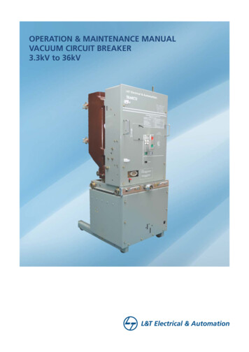
CONSTRUCTIONSECTION B4.0 CONSTRUCTIONSTRUCTUREThe external view of this breaker is shown in Figure 2. The circuitbreaker consists of a moulded insulator, housing three (3)vacuum interrupters and an operating mechanism which usesthe spring stored energy system.Figure 2:External view of the 12kV upto 1250A CBFigure 3:External view of the- 12kV / 2000A CBFigure 4:External view of the- 12 kV / 3150A CBFigure 5:External view of the 33kV 2000A CBVACUUM CIRCUIT BREAKERTYPE:RATED VOLTAGERATED INSUL. LEVEL12kVIMPULSE75kVp1 Min p.f. 28kVrms50/60HZRATED FREQUENCYRATED NORMAL CURRENTRATED SHORT TIME CURRENTRATED S.C. DURATION3sRATED S.C. BREAKING CURRENTRATED S.C. MAKING CURRENTRATED OPERATING SEQ.O-0.3s -CO- 3MIN- CORATED CLOSING COIL VOLT.RATED TRIP COIL VOLT.RATED MOTOR SUPPLY VOLT.WEIGHTSERIAL NO.MANUFACTURED IN YEARINTERNATIONAL STANDARD IEC 62271-100Rating PlateOperation & Maintenance Manual09
CONSTRUCTIONSECTION BOperating Pin forTest Service IndicatorSocket forSpring Charging HandleTrip ButtonClosing ButtonIndicatorsOperationCounterControl PlugLocking HandleSocket forRacking handleEarthingcontactVCB wheelsFigure 6 - 12kV 800A VCB - FRONT VIEWContact ArmsJaw ContactVCB MechanismVacuumInterruptersTrip / Close ButtonControl PlugVCB RackingWheelEarthingContactFigure 7 - 12kV 800A VCB - SIDE VIEWOperation & Maintenance Manual10
CONSTRUCTIONSECTION BOperating Pin forTest Service IndicatorSocket forSpring Charging HandleDescription plateTrip ButtonClosing ButtonVCB Open/Close IndicatorSpring charged /Discharged IndicatorOperationCounterControl PlugLocking HandleSocket forRacking handleVCB wheelsFigure 8 - 12kV / 3150A VCB - FRONT VIEWContact ArmsVCB MechanismVacuumInterruptersTrip / Close ButtonControl PlugVCB RackingWheelEarthingContactFigure 9- 12kV / 3150A VCB - SIDE VIEWOperation & Maintenance Manual11
OPERATIONSSECTION BOperating Pin forTest Service IndicatorVCB - 33kV 2000ADescription PlateSocket forCharging HandleTrip ButtonClosing ButtonIndicatorsOperationCounterControl PlugLocking HandleSocket forRacking handleVCB wheelsFigure 10 - 33kV VCB - FRONT VIEWContact ArmTulip ContactVacuumInterruptersVCB MechanismTrip / Close ButtonInterrupterHousingControl PlugVCB RackingWheelEarthingContactFigure 11 - 33kV VCB - SIDE VIEWOperation & Maintenance Manual12
OPERATIONSSECTION B4.1 OperationsThe motor energy-storing mechanism of the breaker is shown inFigure 12.drives the vacuum interrupters through the wipe spring, and thecircuit breaker closes.CAUTION: DO NOT repeat the closing operation once thebreaker is closed.i) Charging of Closing springWhen the power supply is connected to the operation circuit,energy from the motor is stored in the closing spring. When thespring changing is complete, the limit switches cuts motorsupply. The indicator turns from white to yellow CHARGEDcondition, con rming that the spring charging is complete. Asthe closing spring may be released by a closing signal, the limitswitch closes when the closing operation terminates, causingthe motor to run.ii) Closing operationWhen the closing coil is excited by a closing signal, the closingcatch is released and the closing cam is rotated by the closingspring, which in turn rotates the main shaft. The main shaftiii) Tripping operationWhen the tripping coil is excited by a tripping signal, the trippingcatch is released, and the breaker is opened by the openingspring.iv) Trip-Free OperationTrip-free operation performed by the energy storage mechanismshown in Figure 13-A shows the open state of the energystorage mechanism. Figure 13-B shows the state immediatelyafter the closing operation. When a tripping signal is deliveredwith a closing signal, opening operation shall be performedpreferentially as shown in Figure 13-C.Closing SpringSpring ChargingMotorOpening CoilManual TripPush ButtonClosing SpringAuxiliarycontactsOpening SpringManual ClosePush ButtonSpring Charges/Discharge IndicatorClosing CoilWipe SpringBreaker StatusIndicatorOil DamperMechanicalCounterFigure 12 : Mechanism for spring charging breakerOperation & Maintenance Manual13
OPERATIONSSECTION B(A) Normal Condition(B) Spring chargedCondition (ready for Close)(C) Close & springdischarged (ready for Trip)(D) Charging mode(E) Charged & Readyfor close(F) Trip, Charged & Readyfor closeFigure 13 : Motor stored energy mechanismOperation & Maintenance Manual14
OPERATIONSSECTION B4.2 Control Circuitcompleted. When the external operations switch CS (1) is closed,the circuit IL-b-Yb-Vb-CC energizes the closing coil, thus closingthe breaker. Once the breaker is closed, the auxiliary switch (b)changes over, thus de-energizing the closing coil. The auxiliaryrelay Y energizes to cut off the supply to the closing coil, thusachieving the antipumping feature.4.2.1 Operations for motorized charged spring.(a) ClosingFigure 14 shows the condition in which the charging isSchematic control wiring diagramVEDI ON P/BOFF P/B DIHP331511AP DEVICE1APHT K21412A4 A715 EL36B0624 25 2326 35 28A03 A04 A07 A05 B03 A0827A06LS232N1212N342N2VEINDICATION ON PANELLEGENDCCTCMabAPLSAX1,2DESCRIPTIONCLOSING COILTRIPPING COILSPRING CHARGING MOTORBKR. AUX. CONTACT - N/OBKR. AUX. CONTACT - N/CANTI-PUMPING DEVICESPRING CHARGE LIMIT SWITCHAUX. SWITCH 1Operation & Maintenance Manual67534A3 A7 N3 P314 13 12 11HT212019AB1810C17A52198A41615A08 A06 A05 A04 A03 A07 LS28 27 26 25 24 NDARY DISCONNECTING SWITCH (SDS)ARRANGEMENT (FRONT VIEW)15
OPERATIONSSECTION B(b) Automatic charging of closing spring.The microswitch LS will close simultaneously with the breaker,thus energizing the control relay X. With the relay X energized,the circuit LS-LS-Xa-M-Xa-F starts the motor until the chargingof the closing spring is completed. Once the spring is fullycharged, LS opens, de-energizing the relay X and the motor.Spring charging takes about 3.5 seconds.pin 2 is in the lower position (below oor plate) when theplug is not inserted.The plug cannot be inserted because the insertion hole isclosed by the lock pin 1.Insertion holeSocket for plugInterlockplate(c) TrippingThe tripping of the breaker involves only the a1 contact. Closingthe external switch CS (2) will energize the trip coil and trip thebreaker. On tripping the breaker, the auxiliary switch (a) changesover, hence de-energizing the trip coil (TC).Front View4.3 Interlock of Control Circuit PlugFloorplateLockpin 2Lockpin 1Side ViewFigure 14 : DISCONNECTED position of panelPanel SideSecondaryDisconnectingPlugb) Preparation for plug connectionWhile pressing down the red lever and keeping it held down,insert the plug into the insertion hole.During the insertion, the breaker cannot be moved to theservice position because lock pin 2 is in the lower position.Breaker SideSocket for PlugInsertion holeSecondarydisconnected pinLockingHookLockpin 1SecondaryDisconnectingPlug AssemblyInterlockpinInterlockplateLockpin 2Front ViewSide ViewFigure 15 : Preparation for plug connectionWhen using the secondary disconnect plug, follow theprocedures described in the following page:a) DISCONNECTED position of panelBreaker cannot be moved to service position because the lockOperation & Maintenance Manual16
OPERATIONSSECTION Bc) Incomplete connection of the plugd) Complete connection of the plugBreaker cannot be moved to the connected position becauselock pin 2 is not raised by the interlock pin of the secondarydisconnect plug.During insertion of the plug, the interlock plate is pushed bythe interlock pin and the lock pin 2 is raised.During removal of the plug from the uncompletedconnection, lock pins 1 and 2 return to the position shown ingure 14.Insertion holeConnecting the plug as shown in gure16 raises the lock pin1and breaker can be moved to the connected position.In the connected position, coupling of the interlock pin andthe lock pin 1 prevents removal of the plug.The lever cannot be lowered during removal of the plug in theconnected position because lock pin 1 strikes against theoorplate.To ensure proper connection of the plug and its contact pins,the plug must be fully home and not tilted to one side. TheLocking Hook is provided to ensure this.Secondarydisconnected plugInsertion holeInterlockpinLeverLookpin 1FloorplateLookpin 2Front ViewLeverFloorplateSide ViewFigure 16 : Incomplete connection of the plugFront ViewSide ViewFigure 17 : Complete connection of the plugOperation & Maintenance Manual17
PUTTING INTO SERVICESECTION B5.0 OPERATING INSTRUCTIONS5.1 - Operating Instructions for VCB rack-in and Rack OutVCB Operation:The breaker is of the horizontal withdrawal and horizontal isolation type of truck. It is designed with the interlocks against accidentaland dangerous operations.VCB Rack-IN or Rack-OUT operations to be carried out with VCB compartment door closed only.It can be inserted in to CONNECTED/SERVICE position or withdrawn to DISCONNECTED / TEST position with the aid of a rackinghandle provided. Before starting VCB Operation please ensure that all Panel components are known.VCB Test ServiceIndicatorVCB RackingMechanism InterlockHandle & latchFigure 5.1 A - VCB in DisconnectedFigure 5.1 B - VCB in TestFigure 5.1 C - VCB in ServiceAs shown in Figure 5.1 A VCB is in DISCONNECTED position.As shown in Figure 5.1 B VCB is in TEST Position. Indication shown on VCB door will be in Green Colour.As shown in Figure 5.1 C VCB is in Service Position. Indication shown on VCB door will be in Red Colour.Note - For Detail view of Test Service Indicator & VCB Handle with latch please refer Figure No 5.5.VCB Racking-In to TEST Position Operation Sequence.While racking-in VCB to test position, ensure the racking mechanism interlock handle in latched / locked position.Hold the Breaker handles & gently push the Breaker into panel.Unlatch the racking mechanism interlock handle to lock the Breaker with panel.Interlock plate goes into the slots provided at the side of the panel. These handle operate left to right in horizontal plane.Breaker is now in TEST Position.Operation & Maintenance Manual18
PUTTING INTO SERVICESECTION B5.2 - Control Plug ArrangementA removable plug at the panel connects these control wires to the xed wiring at the metering compartment.Whenever Panels are taken for Maintenance activity, please keep the control plug wire as shown in Figure 5.2 so as to avoidany disturbance & damages to Control plug wire.Ensure that the plug makes full connection before fastening the clasp.The breaker can only be racked into the SERVICE position when the secondary control plug is inserted.Control circuit plug can be inserted by moving the Red lever downwards.VCB Test ServiceIndicator Green TestRed - ServiceControl Plug WireMountingArrangementControl PlugLatch for HandleRed Lever ( belowControl Plug)VCB raking HandleFigure 5.2 - Control Plug ArrangementOperation & Maintenance Manual19
PUTTING INTO SERVICESECTION BVCB Racking Out to Disconnected Position Operation Sequence.While racking out VCB to Disconnected position, Pull the Interlock Plates and latch the Handle.Hold the Breaker handles & gently pull the Breaker out of panel.Now the Breaker is in DISCONNECTED Position.5.2.1 - VCB Door Operating Instructions are as followsLatch PadlockLOCKUNLOCKDoor HandleLOCKFigure 5.2.1 A - Door LockedDoor LatchLOCKUNLOCKFigure 5.2.1 B - Door latch OpenUNLOCKFigure 5.2.1 C - Door OpeningA. Door Opening SequenceBefore door opening ensure the VCB in in Open condition.Door is in closed position with padlocking arrangement as shown in Figure 5.2.1 A.For Door Opening Padlocked to be removed, latch to be opened (rotate anticlockwise) as shown in Figure 5.2.1 B.Door Handle shall be lifted upwards and door shall be opened as shown in Figure 5.2.1 C.B. Door Closing SequenceEnsure the wheel bracket plates are at closed position.Lift the VCB Door handle (if necessary), hold it in same position and swing the door towards panel.Once the doorclockwise).ushing with the panel, push the VCB door handles downward and latch the handles (rotatePadlock the latch.Operation & Maintenance Manual20
PUTTING INTO SERVICESECTION B5.2.2 - VCB Rack-in- & Rack-Out Operation Sequence - Closed DoorCIRCUIT BREAKER RACK-IN OPERATION SEQUENCE :1. ENSURE THE FOLLOWING BEFORE RACK-IN;A VCB IS IN TEST POSITION.B CONTROL PLUG IS PROPERLY CONNECTED TO VCB.C VCB IS IN OPEN CONDITION.2. SWING THE DOOR FOR CLOSING AND LOCK IT BY MOVING HANDLE DOWN.3. PAD LOCK DOOR HANDLE.4. ROTATE THE KNOB OF SOCKET FOR VCB RACKING HANDLEANTICLOCKWISE AND INSERT THE VCB RACKING HANDLE.5. ROTATE THE RACKING HANDLE CLOCKWISE UNTIL;A VCB POSITION INDICATOR SHOWS SERVICE ANDB MECHANICAL RESISTANCE IS FELT TO ROTATE THE HANDLE.6. REMOVE THE RACKING HANDLE.7. ROTATE THE KNOB OF; SOCKET FOR VCB RACKING HANDLECLOCKWISE TO COVER RACKING HOLE.CIRCUIT BREAKER RACK-OUT OPERATION SEQUENCE :1. ENSURE THE FOLLOWING BEFORE RACK-OUT;A VCB IS IN OPEN CONDITION.B VCB POSITION INDICATOR SHOWS SERVICE POSITION.2. ROTATE THE KNOB OF SOCKET FOR VCB RACKING HANDLE ANTICLOCKWISE AND INSERTTHE VCB RACKING HANDLE.3. ROTATE THE RACKING HANDLE ANTICLOCKWISE UNTIL;A THE VCB POSITION INDICATOR SHOWS TEST ANDB THE HANDLE STOPS ROTATING.4. REMOVE THE RACKING HANDLE.5. ROTATE THE KNOB OF SOCKET FOR VCB RACKING HANDLE CLOCKWISE TO COVERRACKING HOLE.6. RELEASE PAD LOCK FROM DOOR HANDLE.7. UN-LOCK DOOR BY MOVING HANDLE UP & SWING IT FOR OPENING.Operation & Maintenance Manual21
PUTTING INTO SERVICESECTION BTo withdraw the breaker from the panel, rst remove thecontrol circuit plug. This is done by rst opening the clasp,then pressing down the red interlock lever and holding itdown while withdrawing the plug. Exert a pulling pressure onTest Positionthe left-hand side of the plug and ensure that it is in line withthe socket. Do not pull the plug on the right hand side as thismay distort the holding bracket and cause misalignment ofthe shaft.Inter. PositionService PositionFigure 18 : Procedure for inserting the breaker into the cubicleOperation & Maintenance Manual22
PUTTING INTO SERVICE5.3 Interlocks5.3.1 - General Interlocks ProvidedA) The Racking-in & Racking-out of circuit breaker is notpossible unless it is OFF.B) Circuit breaker can be closed only when it is in the service ortest position.C) The operation of Circuit breaker is not possible while it is inthe intermediate position.D) Circuit breaker cannot be racked-in unless the control plugis inserted.E) The operation of Circuit breaker is not possible unlesscontrol plug is inserted.F) It shall not be possible to remove the control plug while theCircuit breaker is in service position.G) It shall not be possible to remove the control plug while theCircuit breaker is in the intermediate position.H) It shall be possible to remove the control plug if Circuitbreaker when in test disconnected position, irrespective ofCircuit breaker status.I)Circuit breaker can be fully withdrawn out of itscompartment only when the control plug is removed.J) It is possible to operate Circuit breaker unless earth switchis in open position.K) It shall not be possible to move the Circuit breaker fromdisconnected position/test position into service positionwhile earthing switch is closed.Operation & Maintenance ManualSECTION BL) It is not possible to operate earth switch unless Circuitbreaker is in test/disconnected position.M) It is not possible to close the earth switch with Circuitbreaker in service or intermediate position.N) It is not possible for Circuit breaker to operate unless springis fully charged.P) Rating error preventer is provided to prevent rack in withdifferent rating of the Circuit breaker.Q) It shall not be possible to open the door while circuit breaker,is in service position.R) Door can be opened only if Circuit breaker is in Testposition.S) Bypassing arrangement is provided to unlock the door incase of emergency.T) Safety shutter opens when the VCB is racked-in to serviceposition.U) Safety shutter closes automaticallyis withdrawn from the service positiononcetheVCBV) VCB of same rating can be interchanged.5.3.2 - Padlocking FacilityA) VCB door key handleB) Safety shutter23
MAINTENANCE AND INSPECTIONSECTION B6.0 MAINTENANCE AND INSPECTION6.1 Check Points For Periodical InspectionGeneral checks should be done one year after installation andonce every 2 years thereafter, depending on severity of usage &NO CHECK POINTCHECK ITEMCHECK METHODenvironmental conditions. This should be done against a welldocumented schedule of requirements.CRITERIABy tighteningTightness of bolts them with screwNo loose connections.driver and wrenchand nuts.with torque mark123Entire CircuitBreakerControl circuit(Section 4.2)The breaker shouldbe clear of dustand stains.WHAT TO DORe-tighten looseconnections.Clean with a vacuumcleaner. Wipe with aclean, dry cloth andrecommended cleaningagent (AS66).Dust and foreignmatter.Visual checkDeformation,excessive wearand damage.Visual checkNo deformation,excessive wearor damage.Replace parts,if necessary.Lost or missingparts.Visual checkNo missing partsReplace missing parts.Electrical closingand trippingCheck at theDISCONNECTEDposition.TerminalFREQUENCYOnce in2 yearsThe closing andCheck circuits andtripping operationsthe closing and trippingcan be done smoothly. devices.Once in2 yearsMotor can springcharge automatically.When the motor cannotspring charge, check theelectric connection.Tighten withscrew driverNo loose screws.Re-tighten.Once in2 yearsMoulding andContactsVisual checkNo damage ordeformation.Replace whendamaged.Once in2 yearsDust and foreignmatterVisual checkThere should be nodust and foreignmatter.Remove foreign matterwith pressurized air.Auxiliary switchSmooth operation Manual operation4Operation should besmooth.OperatingmechanismLubricant ofbearing pins.Check by sightand touch.Shaft of closingand trippingportion.Visual checkOperation & Maintenance ManualClean off old lubricantand apply a smallamount of freshlubricant, if necessary.Once in2 yearsMust rotate smoothly.24
MAINTENANCE AND INSPECTIONNO CHECK POINTCHECK ITEMContact wear5CHECK METHODVisual checkNumber ofOPEN CLOSEDoperation.Main circuitdisconnects/Contact ngerDis-colourationof contactsCounter readingVisual checkContaminationVisual checkand discolourationMeasuringlocationMeasurementof insulationresistanceResistanceWhen the counterreading reaches10,000 (for the ratedcurrent interruption),check the internalpressure. The nextcheck shall be done atthe reading of 15,000.After every30 faultoperations(dependingon the severityof the fault),500 mechaicaloperation oronce in 2 years,whichevercomes rst.Replace the vacuuminterrupter if the internalpressure is insuf cientor when the counterreading reaches 20,000.Once in2 yearsClean the contactThere should be a thin surface of old greaselm of electrical grease and apply a thin lmon the contact surface. of new grease.There should be notracking marks, cracksor damages.TesterMain conductorGround/ Mainconductors5000VControl circuitGround500VOperation & Maintenance ManualFREQUENCYReplace the vacuuminterrupter when vacuumpressure is insuf cient.There should be noforeign matter.Main barrierWHAT TO DORed wipe mark mustIf red wipe mark cannotbe visible when breaker be seen, replace theis in CLOSED position. vacuum interrupter.Refer to section 6-278CRITERIAVacuuminterrupterVacuum pressure6SECTION BClean with pressurizedair and then wipe witha clean cloth.Replace when damaged.When the insulationresistance between themain circuit terminals islow, clean the surface ofthe vacuum interrupterwith a dry cloth andthen take themeasurements agai
Operation & Maintenance Manual 01 1.0 - INTRODUCTION Field Service Operation E&A can provide competent, well-trained Field Service Representatives to provide technical guidance and advisory assistance for the installtion, overhaul, repair and maintenance of E&A equipment, processes and systems. Contact sales ofces