Transcription
NUMBER9Understanding Vacuumand Vacuum MeasurementVACUUMFURNACEREFERENCESERIES
SOLAR ATMOSPHERES, INC.Understanding Vacuumand Vacuum MeasurementWritten By:Reál J. Fradette, Senior Technical Consultant, Solar Manufacturing, Inc.Contributors:William R. Jones, CEO, The Solar Atmospheres Group of CompaniesTrevor Jones, Principal Engineer, Solar Atmospheres, Inc.Editor:Patricia Niederhaus, Executive Technical Administrator, Solar Atmospheres, Inc.Layout & Illustrations:Andrew Nagy, Graphic Designer, Solar Atmospheres, Inc.
TAir Compositionhe purpose of this paper is to provide a better understanding of vacuum, including anexplanation of vacuum, a definition and description of vacuum measuring instrumentation andan explanation of their application to vacuum furnace operation.at 50% Relative HumidityGasPercentExplaining VacuumN278.08Vacuum can be defined as a space that is empty of matter; however, achieving such an empty spaceis essentially impossible on earth. Instead, vacuum is best described as a space with gaseous pressuremuch less than atmospheric pressure. Physicists and vacuum scientists describe this lack of a “perfectvacuum” in manmade chambers, such as production furnaces, as partial pressure or partial vacuum. 1O220.95Ar0.93CO20.033Ne1.8 10-3He5.24 10-4CH42.0 10-4Kr1.1 10-4H25.0 10-5N2O5.0 10-5Xe8.7 10-6H2O1.57The quality of a vacuum is indicated by the amount of matter remaining in the system, so that a highquality vacuum is one with very little matter left in it. Vacuum is primarily measured by its absolutepressure.At room temperature and normal atmospheric pressure, one cubic foot (0.03 cubic m) of air containsapproximately 7 1023 molecules moving in random directions and at speeds of around 1,000 milesper hour. 2 The momentum exchange imparted to the walls is equal to a force of 14.7 (psia) poundsfor every square inch of wall area. 2 This atmospheric pressure can be expressed in a number of units,but until relatively recently it was commonly expressed in terms of weight of a column of mercury760 mm high. 2 Thus, one standard atmosphere equals 760 mm Hg.Table 1Creating a Vacuum The PumpdownThe distance between molecules is a function of pressureand is known as the mean free path (MFP). 3 As thechamber is pumped down into vacuum and molecules areremoved, the MFP becomes greater and greater.1.00E 81.00E 71.00E 61.00E 51.00E 41.00E 31.00E 21.00E 11.00E 01.00E-1TorrFigure 1 - Mean Free Path Vs PressureVacuum Units of MeasurementMeasuring vacuum, as with any kind of measuring, requires standard units of measure. Inches or millimeters of mercury, torr, and micron arethree units of measure typically associated with the vacuum furnace industry. Other fields of vacuum use Pascals (Pa or kPa.)Understanding Vacuum and Vacuum 09E-001.0011E-001.1.1E-21E-001.001.As pressure decreases in a chamber, fewer molecules arepresent and the mean free path increases. Similarly, as thegas density reduces, there are fewer chances of molecularcollision. This correlation between the MFP and pressureis shown in Figure 1. Air molecules are usually removedfrom the chamber through a type of positive displacementpump such as an oil-sealed rotary pump.1.00E 9FeetThe pumpdown process begins with air at atmosphericpressure in a chamber attached to a vacuum pump. Thevacuum pump removes gas molecules from the chamberto reach the desired vacuum. Air at atmospheric pressureis a combination of gasses as shown in Table 1. Therelative gas composition will be important later on in thispaper.Gas molecules are always moving and colliding, moleculeto molecule. Gas molecules at atmospheric pressure arevery close together, so the collisions are very short.
Because of the work of 17th century scientist EvangelistaUnits of Vacuum MeasurementTorricelli, we know that the atmosphere generally exertsenough pressure at sea level to support about a 30-inchinHg (abs.)TorrMicrons(760mm) column of mercury. From that foundation,1 inHg125.42.54 x 104we can measure decreases in atmospheric pressure in1 Torr3.937 x 10-211000terms of inches or millimeters of mercury. Thus, a 10%drop in atmospheric pressure would indicate a 3-inch1 Micron3.937 x 10-51 x 10-31fall in the height of our column of mercury. In this way,vacuum came to be measured by the difference betweenTable 2normal atmospheric pressure and pressure in the systembeing measured. Thus, a 10% decrease in gas density from atmospheric pressure would be measured as a 3-inch vacuum. For everyday vacuummeasurements such as in weather forecasting, inches of mercury function well, but for measurements on a finer scale, other units are needed.One “torr,” a unit named in honor of Torricelli, is equivalent to one millimeter of mercury, yielding the figure of 760 torr as normal atmosphericpressure at sea level. Torr as units of measure are typically used for vacuums in the 1 to 760 Torr range. For measurements of vacuum on aneven smaller scale, the “micron” is the term of use. One micron is equal to 0 .001 Torr (10-3 Torr). Microns (represented by the symbol µ) aretypically used to measure vacuums in the range of 10-3 to 1 Torr. For heat treating purposes, torr and micron are the most commonly used unitsof measure. Table 2 gives conversion factors for the three units discussed above.Vacuum LevelsVacuum quality is subdivided into ranges according to the technology required to achieve it or measure it. A typical distribution of theuniversally accepted ranges can be found in Table 3. 1Atmospheric Pressure – is variable but is standardized at 760 Torr or 101.325 kPa.Low Vacuum – also called rough vacuum, is a vacuum that can be achieved or measured by basic equipment such as a vacuum cleaner.Medium Vacuum – is a vacuum that is typically achieved by a single pump, but the pressure is too low to measure with a mechanical manometer.It can be measured with a McLeod gauge, thermal gauge, or a capacitance gauge. (Instrumentation to be discussed later.)High Vacuum – is vacuum where the MFP of residualgasses is longer than the size of the chamber or of theobject under test. High vacuum usually requires multistage pumping and ion gauge measurement. NASA hasrevealed that the vacuum level recorded on the moon was1x10-9 Torr. 1Ultra-High vacuum – requires baking the chamber toremove trace gasses and other special procedures. Moststandards define ultra-high vacuum as pressures below10-8 Torr.Vacuum Level RangesAtmospheric Pressure760 TorrLow Vacuum (Rough)760 to 25 TorrMedium Vacuum (Rough)25 to 1 x 10⁻³ TorrHigh Vacuum (Hard)1 x 10⁻³ to 1 10-9 TorrUltra High Vacuum1 x 10-9 to 1 10-12 TorrExtremely High Vacuum 1 x 10-12 TorrOuter Space1 x 10-6 to 3 10-17 TorrDeep Space – is generally much emptier than anyartificial vacuum.Table 3Perfect Vacuum – is an ideal state of no particles at all. It cannot be achieved in a laboratory, although there may be small volumes which, for abrief period, happen to have no particles of matter in them.Types of Vacuum Measuring InstrumentsAs it has become practical and desirable to create higher and higher vacuums, it has also become necessary to assess the level of those vacuumsaccurately.Absolute pressure is measured relative to perfect vacuum (0 psia) with zero as its zero point. Gauge pressure is relative to ambient air pressure (14.5psia), using atmospheric pressure as its zero point (0 psig 14.5 psia).Many gauges are available to measure vacuum within a vacuum furnace chamber. These gauges vary in design based on the particular rangeof vacuum they are analyzing. Table 4 shows the various gauges that we will be discussing in the following pages and their respective range ofperformance (shaded area).Understanding Vacuum and Vacuum Measurement2
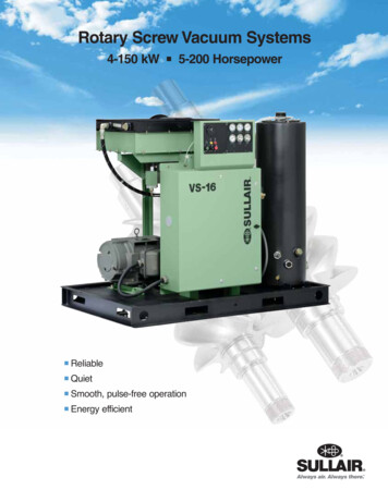
Effective Operating Ranges of Vacuum onometerPirani GaugeT/C GaugeHotCathodeGaugeColdCathodeGaugeMcLeodGauge103 Torr102 Torr101 Torr100 Torr10-1 Torr10-2 Torr10-3 Torr10-4 Torr10-5 Torr10-6 Torr10-7 Torr10-8 Torr10-9 Torr10-10 Torr10-11 TorrTable 4Hydrostatic GaugesTorricelli’s DiscoveryInstruments for measuring the emptiness of a given space have been used for hundreds of years, making use of the properties of gases todetermine their relative absence. The barometer, a device used for measuring air pressure, was invented in 1643 by the Renaissance Florentinescientist Evangelista Torricelli. Because we are living submerged in an ocean of air, the atmosphere is pressing down on us. Due to local heatingand cooling, areas of lower and higher atmospheric pressure periodically sweep over us. The areas of lower pressure are in a sense areas ofvacuum, as the gasses of the air around us are relatively less dense there. Torricelli found that the pressure of the atmosphere at sea level pressingdown on a well of mercury would support a nearly 30-inch column of mercury in a tube upended in the reservoir of mercury. The mercury inthe column would not flow down into the well because of the counterbalancing atmospheric pressure on the surface of the mercury in the well.From that beginning, more sophisticated and precise devices have been designed to measure lower and lower masses of gas in a given volume.Hair SpringTwo of the most common hydrostatic measuring devicesare the Bourdon gauge in Figure 2 and the McLeod gauge inFigure 3.Bourdon TubeScale6030The Bourdon Gauge/Diaphragm GaugeThe Bourdon gauge, also known as the diaphragm gauge,shown in the Figure 2, accurately and continuously indicatesthe pressure from approximately atmospheric pressure (760Torr) to 20 Torr.Link0-15Pinion & Sector GearsThe pressure gauge uses the principle that a flattened tubetends to straighten or regain its circular form in cross-sectionInlet Pressurewhen pressurized. Although this change in cross-section mayFigure 2 - Bourdon Tube Gaugebe hardly noticeable, and thus involving moderate stresseswithin the elastic range of easily workable materials, the strain of the material of the tube is magnified by forming the tube into a C shape or evena helix, such that the entire tube tends to straighten out or uncoil, elastically, as it is pressurized. Eugene Bourdon patented his gauge in France in1849, and it was widely adopted because of its superior sensitivity, linearity, and accuracy. 5Understanding Vacuum and Vacuum Measurement3
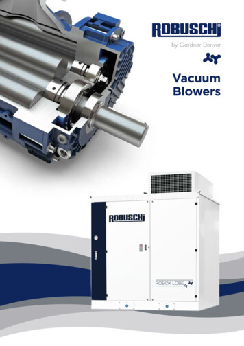
In practice, a flattened thin-wall, closed-end tube is connected at the hollow end to a fixed pipe containingthe fluid pressure to be measured. As the pressure increases, the closed end moves in an arc, and thismotion is converted into the rotation of a segment of a gear by a connecting link that is usually adjustable.A small-diameter pinion gear is on the pointer shaft, so the motion is magnified further by the gear ratio.The positioning of the indicator card behind the pointer, the initial pointer shaft position, the linkage lengthand initial position all provide means to calibrate the pointer to indicate the desired range of pressure forvariations in the behavior of the Bourdon tube itself. Differential pressure can be measured by gaugescontaining two different Bourdon tubes, with connecting linkages. 6Bourdon tubes measure gauge pressure relative to ambient atmospheric pressure, asopposed to absolute pressure; vacuum is sensed as a reverse motion. Some barometersuse Bourdon tubes closed at ends (but most use diaphragms or capsules, see below.) When the measuredpressure is rapidly pulsing, such as when the gauge is near a reciprocating pump, an orifice restriction in theconnecting pipe is frequently used to avoid unnecessary wear on the gears and provide an average reading.When the whole gauge is subject to mechanical vibration, the entire case including the pointer and indicatorcard can be filled with an oil or glycerin. Tapping on the face of the gauge is not recommended as it will tendFigure 3 - McLeod Gaugeto falsify actual readings initially presented by the gauge. The Bourdon tube is separate from the face of thegauge and thus has no effect on the actual reading of pressure. Typical high-quality modern gauges provide an accuracy of 2% of span, and aspecial high-precision gauge can be as accurate as 0.1% of full scale. 6McLeod GaugeThis gauge is a modification of a manometer that can measure absolute pressure of gasses quiteaccurately. 7To Vacuum Being MeasuredReadingThe main advantage of the McLeod gauge is that its calibration is unaffected by the type ofgas in the system. Many gasses such as hydrogen, helium, carbon dioxide, and many othergasses in a vacuum system will wreak havoc with the calibration of most other types ofvacuum gauges. However, as long as the condensable vapors are trapped out, readings fromthe McLeod gauge can be used to calibrate other gauges. 8KnownVolumeAFrom MercuryReservoirBAs shown in Figure 4, it traps a fixed volume and then compresses its volume, raising thepressure to a point where it can be easily read.The McLeod gauge measures pressure intermittently rather than continuously. A vacuum isestablished with the mercury level shown in dark gray (Figure 4(B)). The mercury is raiseduntil the level in the tube connected to the vacuum is equal to the top of the sealed capillary. The reading difference now indicates the vacuummeasurement. The McLeod gauge was invented by H.G. McLeod in 1974 to measure gas pressure of or between 10-2 and 10-7 Torr. 9Figure 4 - McLeod Gauge Operation10Capacitance Manometer GaugesThe capacitance manometer gauge is a pressure gauge used to measure vacuum fromatmospheric pressure to 10-5 Torr dependent on the given sensor applied. 11ElectronicsA capacitance sensor operates by measuring the change in electrical capacitance that resultsfrom the movement of a sensing diaphragm relative to some fixed capacitance electrodes(Figure 5). The higher the process vacuum, the farther it will pull the measuring diaphragmaway from the fixed capacitance plates. In some designs, the diaphragm is allowed to move. Inothers, a variable DC voltage is applied to keep the sensor’s Wheatstone bridge in a balancedcondition. The amount of voltage required is directly related to the pressure.The great advantage of a capacitance gauge is its ability to detect extremely small diaphragmmovements. Accuracy is typically 0.25 to 0.5% of reading. Thin diaphragms can measuredown to 10-5 Torr, while thicker diaphragms can measure in the low vacuum to atmosphericrange. To cover a wide vacuum range, one can connect two or more capacitance sensingheads into a multi-range desHigh-VacuumReference CavityFigure 5 - Capacitance Manometer GaugeThe capacitance diaphragm gauge is widely used in the semiconductor industry, because its Inconel body and diaphragm are suitable for thecorrosive services of this industry. They are also favored because of their high accuracy, immunity to contamination, and gas type species.Understanding Vacuum and Vacuum Measurement4
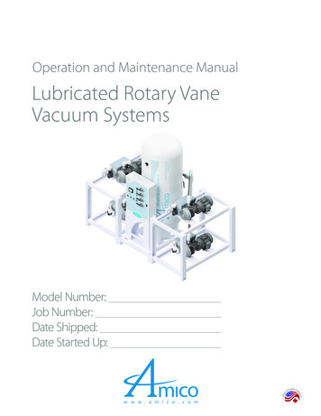
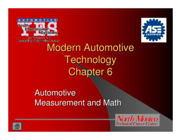
Pirani GaugesThe Pirani gauge is a thermal conductivity gauge used tomeasure pressure in a vacuum. The gauge is able to givea pressure reading due to a heated metal wire suspendedin the vacuum system to be measured as shown in Figure6b. Gas molecules in the system collide with the wireallowing it to emit heat and cool. As the vacuum ispumped down, there are fewer gas molecules to affectthe wire and the wire heats up. When the wire is heated,the electrical resistance increases and a circuit attachedto the wire detects the change in resistance. Once thecircuit is calibrated, it can directly correlate the amount ofresistance to the pressure in the vacuum chamber.TungstenResistive HeatersStainless SteelCaseFigure 6a - Pirani Gauge 12Figure 6b - Pirani Gauge 13There are two types of Pirani gauges: constant currentand constant resistance. Each refers to how the electrical measurement of the wire is controlled. The constant current gauge has a power supplygiving off a consistent amount of energy to the metal filament. The current is the control and the resistance is the variable. The varied resistanceis proportional to the pressure in the vacuum. The constant resistance gauge has a power supply which varies the current based on the constantresistance. The variation in the current is proportional to the pressure in the vacuum.The Pirani gauge is used to measure pressures between 0.5 Torr to 10-4 Torr. Before using the gauge, the apparatus may need calibrating to obtainaccurate readings depending on the thermal conductivity and the heat capacity of the gas.Thermocouple GaugesA thermocouple (T/C) gauge works very similarly to a Pirani gauge. The difference is that the temperature of the wire is measured precisely bythe T/C, which is attached to the wire. The current is determined based on the resistance. This gauge is normally used for comparison purposesand the sensitivity varies based on the pressure and the strength of the current. The reading is on a minivolt meter calibrated to show pressure,but it must be calibrated for each different gas other than air and nitrogen. Another disadvantageis that it is not marked in a linear order. At low pressures, the scale markings are spread apart andin higher ranges, the marks are closer together. For the most part, the thermocouple gauges havethe same advantages and disadvantages as the Pirani gauge although the thermocouple gaugeis considered to be less expensive and more user friendly. Figure 7 is an example of a typical14thermocouple gauge.ThermocoupleHeatervFeedthrough Pins15Vacuum PortFigure 7 - Thermocouple GaugeIonization GaugesEvery modern vacuum furnace capable of operating inhigh vacuum relies on some form of ionization gaugefor pressure measurements under 10-3 Torr. Thereare two competing ionization gauge technologiesto choose from which are viable means for pressuremeasurements between 10-2 and 10-10 Torr. Theysense pressure indirectly by measuring the electricalions produced when gas is bombarded with electrons.Fewer ions will be produced by lower density gasses.Hot Cathode Ionization GaugeA hot cathode ionization gauge like the one in Figure 8 is composed mainly of three electrodesacting together in a triode, wherein the cathode is the filament. The three electrodes are a collectoror plate, a filament and a grid. Electrons emitted from the filament move several times in back andforth movements around the grid before finally entering the grid. During these movements, someelectrons collide with a gaseous molecule to form a pair of an ion and an electron. The numberof these ions is proportional to the gaseous molecule density multiplied by the electron currentemitted from the filament, and these ions enter into the collector to form the ion current. Since thegaseous molecule density is proportional to the pressure, the pressure is estimated by measuringthe ion current.16Understanding Vacuum and Vacuum Measurement5Ion Collector WireGlass EnvelopeAnode GridFilamentSide ArmMountingTubeFigure 8 - Hot Cathode Gauge 17
Cold Cathode GaugeA cathode is an electrode that emits electrons, that is not electrically heated by a filament. 18There are two types of cold cathode ionization gauges: the Penning gauge and the invertedmagnetron, also known as the redhead gauge. 19MagnetCathodeThis gauge, like the one in Figure 9, makes use of the fact that the rate of ion productionby a stream of electrons in a vacuum system is dependent on pressure and the ionizationprobability of the residual gas. 20Two parallel connecting cathodes and the anode is placed midway between them. Thecathodes are metal plates or shaped metal bosses. The anode is a loop of flattened metal wire,the plane of which is parallel to that of the cathode. A high voltage potential is maintainedbetween the anodes and the cathodes. In addition, a magnetic field intensity is appliedbetween the elements by a permanent magnet, which is usually external to the gauge tubebody.AnodeFigure 9 - Cold Cathode GaugeElectrons emitted travel in helical paths (due to the magnetic field), eventually reaching theanode, thus increasing the amount of ionization occurring within the gauge. Normally the anode is operated at about 2kV, giving rise to a directcurrent caused by the positive ions arriving at the cathode. The pressure is indicated directly by the magnitude of the direct current produced.The pressure range covered by this gauge is from as low as10-7 Torr. It is widely used in industrial systems because it is rugged and simple to use.Vacuum Levels in ProductionVacuum FurnacesCold CathodeSensorRoughing LineRoughing FlowIn discussing vacuum furnace operation andperformance, vacuum levels are usually definedby the capabilities of the vacuum pumps includedon the vacuum furnace system.High Vacuum FlowRoughingValveExhaust FilterForelineMainValveA typical vacuum pump arrangement might looklike Figure 10. Basically, there are three pumpsto provide the following practical vacuum levelranges shown in Table 5.Understanding the Use ofPartial The use of partial pressure is required in manyheat treating and brazing cycles in a vacuumfurnace. It is very important to understandhow the vapor pressure of the materials beingprocessed can be affected by the processtemperature and furnace vacuum level.DiffusionPumpRoughingPumpFigure 10 - Typical Vacuum Furnace Pump ConfigurationPractical Vacuum Pump LevelsVacuum PumpAchievable Range(Torr)Achievable Range(Microns)Mechanical Pump0.05050Vacuum Booster Pump0.01010Oil Vapor Diffusion Pump1 x 100.0001-7Table 5Understanding Vacuum and Vacuum Measurement6VacuumChamber
As a material is processed in vacuum, the temperature atwhich the material will vaporize reduces as the vacuum levelis lowered. In vacuum furnaces, metals tend to volatize attemperatures below their melting point. Table 6 illustrates theeffect of vacuum levels as related to the reducing vapor pressuretemperatures.Vapor Pressure Chart of Certain Metals(oF)Vapor Pressures of Certain MetalsElement10-4Torr10-3Torr10 -2Torr10 –1Torr1.0Torr10 1Torr10 709Carbon41504480485852995817713579038721When the particular metal is part of an alloy, the vapor pressuretemperature of the alloy changes based on the various metalsincluded. It has been established that the total vapor pressureof the alloy is the sum of the vapor pressures of each componenttimes its percentage in the 054703Partial Pressure and Vacuum Furnace ne of the most critical processes performed in a vacuumfurnace is the brazing of materials. As an example, copper iscommonly used as the brazing filler material for brazing steelcomponents. Copper brazing (shown in Figure 11) is typicallyperformed at a high temperature of about 2025-2050 F. If welook at our above chart for copper, the vapor pressure at 760Torr is about 4700 F so that at atmospheric pressure, it wouldrequire this temperature to start to vaporize. However, if welook at the chart at a vacuum pressure of 10-4 Torr, copper beginsvaporizing at about 1895 F. Since we must raise the processtemperature to 2025-2050 F, Table 6 tells us that we must beabove 10-3 Torr (1 micron) to control the vaporization.MercuryMolybdenum3809NeodymiumVapor Pressures of Certain Metals10-3Torr10 -2Torr10 –1Torr1.0Torr10 1Torr10 ugh this is directed toward brazing, there are other vacuumcycles that must be run in partial pressure to minimize possiblematerial vaporization. Stainless and tool steels are now normally403110-4TorrPhosphorusPartial pressure systems are normally incorporated into thevacuum furnace controls to allow for clean, inert gas to beintroduced into the vacuum chamber during a cycle in orderto build the pressure in the chamber to levels high enough tosuppress the vaporization of a particular metal or group of metals.Such partial pressure systems are quite effective. However, itbecomes quite difficult to accurately control at 0.1 Torr or lower,so a typical partial pressure is usually controlled in the 0.5 Torrto 5.0 Torr range to provide more than adequate vaporizationsuppression while not affecting the process conditions.1274Table 6 - Part 1ElementFigure 11 - Copper Brazed 0144458Table 6 - Part 2739564496566110701YttriumUnderstanding Vacuum and Vacuum Measurement8311088163816116604016656471
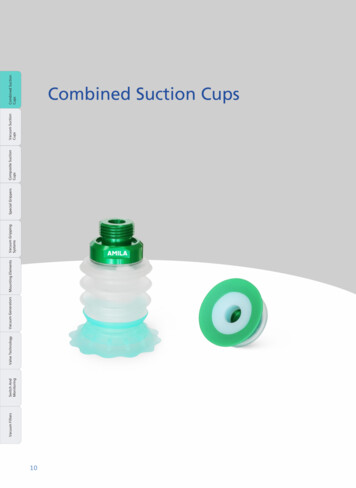
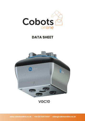
processed in vacuum. However, chromium that is present in these materials will evaporate noticeably at temperatures and pressures withinnormal heat treating ranges.Chromium will begin to vaporize at approximately 1815 F and a vacuum of 1 10-4 Torr when parts are held for an extended time. To avoid this,again the furnace should be operated in a partial pressure in the 0.5 Torr to 5.0 Torr range.MKS ABSGas Correction Factors For Vacuum GaugesVacuum gauges are very sensitive to the type of gas beingused for partial pressure. The reading on the gauge mustbe adjusted per the following studies that have been madefor the various gauge types.The T/C vacuum gauge used in the Figure 12 studies wasa Granville Phillips Convectron gauge. Table 7 showsthe true readings of the partial pressure gas versus thethermocouple gauge reading. This chart is based onactual testing results and can be used to provide the truereadings at the various vacuum levels and can be used asguidance in actual operation.Hydrogen ConvNitrogen Conv100Actual Pressure (Torr)Thermocouple GaugesThe thermocouple gauge is typically very inaccuratewhen reading partial pressure gas levels above 1-2 Torrfor different gasses. This is illustrated in Figure 12 below.Argon Conv10001010.10.01Ionization GaugesThe values in Table 8 are the gas correction factorsfor various gases with respect to nitrogen for both hotcathode and cold cathode ionization vacuum gauges.0.010.11101001000Pressure (Torr) as Indicated by the T/C GaugeFigure 12 - Gas Species Effect on T/C-Type Vacuum GaugesIn a gauge calibrated for nitrogen, where thepredominant gas being measured is other than nitrogen,T/C Gauge Readings Vs True Partial Pressuredivide the actual gauge reading by the appropriate gasTrue NitrogenTrue Argon PPTrue Hydrogencorrection factor to get the corrected pressure value for theT/C Gauge ReadPPGasVacuumGasVacuumPPGas Vacuumspecific gas. These are relative correction factors to be used iningLevelLevelLevelthe high vacuum range of ionization gauges.As shown in Table 8, helium is the most sensitive of the listedgasses and thus becomes very useful during leak checking ofvacuum furnaces. Spraying a small amount of helium around apotential leaking area will be reflected quickly on the vacuumgauge should there be a problem.Nominal relative sensitivity factors cannot be relied uponfor accurate measurements since they are known to varysignificantly between seemingly identical gauges and evenmore for different gauge types, filament materials, andoperating potentials.1 x 10-1 Torr1 x 10-1 Torr1.4 x 10-1 Torr6 x 10-2 Torr1 Torr1 Torr1.9 Torr6 x 10-1 Torr5 Torr5 Torr20 Torr1.4 Torr10 Torr10 Torr400 Torr1.8 Torr20 Torr20 Torr800 Torr2 TorrTable 7Gas Correction Factors for Ionization Gauges Relative to N2Partial Pressure GasNitrogenFor general vacuum use, the discrepancy in reportedmeasurements is not greater than 10% for the common gasses,Airrising to a little above 20% for the less common gases, whereHeliumless accurate information is available. Relative sensitivities areHydrogenpressure dependent and become particularly unreliable above-510 Torr. Where greater precision is required, gauges must beArgoncalibrated individually against the specific gasses and underconditions as close as possible to the operating conditions ofthe vacuum system. 21Understanding Vacuum and Vacuum Measurement8SymbolCorrective FactorRelative to NitrogenN21.00---1.00He0.18H20.46Ar1.29Table 8
Conclusions and SummationThis paper provided a better understanding of vacuum, the types of instruments that record and monitor vacuum levels, and how these devicesrelate to vacuum furnace operation. Measuring vacuum is a very complex subject requiring a good understanding of the best instrumentation available for the application.Vacuum instruments are very sensitive to the pressures being measured and to any contaminating particles that might be present within thechamber being measured.The type of partial pressure gas used to establish safe operating pressure can seriously affect the vacuum gauge reading if not properlyreferenced for accurate reading.Vacuum gauges must be properly calibrated periodically to maintain accuracy and prior to processing critical furnace cycles.Vapor pressures of materials are a serious consideration when establishing proper partial pressure operating levels.Thermocoupl
1 Understanding Vacuum and Vacuum Measurement T he purpose of this paper is to provide a better understanding of vacuum, including an explanation of vacuum, a definition and description of vacuum measuring instrumentation and