Transcription
ENVacuum Status Control PanelInstruction manualDEvierstufige FüllstandsanzeigeEinbauanleitung . . . . . . . . . . . . . . . . . 13FRSystème de surveillance de réservoirMode d'emploi . . . . . . . . . . . . . . . . . . . 19ESSistema de control del depósitoManual de instrucciones . . . . . . . . . . . 26NLTankmonitorsysteemGebruiksaanwijzing . . . . . . . . . . . . . . . 33ITSistema di controllo del serbatoioManuale di istruzioni . . . . . . . . . . . . . . 39FISäiliömittarijärjestelmäOhjekirja . . . . . . . . . . . . . . . . . . . . . . . . 45SVTankövervakningssystemBruksanvisning . . . . . . . . . . . . . . . . . . . 51DATankkontrolsystemInstruktionsvejledning . . . . . . . . . . . . . 57NOTankovervåkningssystemBrukerhåndbok . . . . . . . . . . . . . . . . . . . 63DVS02Vacuum StatusControl Panel
Dometic Vacuum Status Control Panel134212ABDC3A2BC
Dometic Vacuum Status Control PanelA4GCBDHEF3
Dometic Vacuum Status Control Panel4
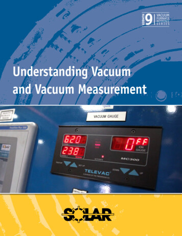
Dometic Vacuum Status Control PanelNotes on using the manualTable of contents1234567891ENNotes on using the manual . . . . . . . . . . . . . . . . . . . . . . . . . . . . . . . . . . . . . . . . . . . . . . . . . 5General safety instructions . . . . . . . . . . . . . . . . . . . . . . . . . . . . . . . . . . . . . . . . . . . . . . . . . 5Intended use . . . . . . . . . . . . . . . . . . . . . . . . . . . . . . . . . . . . . . . . . . . . . . . . . . . . . . . . . . 5 - 6Components . . . . . . . . . . . . . . . . . . . . . . . . . . . . . . . . . . . . . . . . . . . . . . . . . . . . . . . . . . . . 6Specifications . . . . . . . . . . . . . . . . . . . . . . . . . . . . . . . . . . . . . . . . . . . . . . . . . . . . . . . . . 6 - 7Installation . . . . . . . . . . . . . . . . . . . . . . . . . . . . . . . . . . . . . . . . . . . . . . . . . . . . . . . . . . . 7 - 9Operation . . . . . . . . . . . . . . . . . . . . . . . . . . . . . . . . . . . . . . . . . . . . . . . . . . . . . . . . . . . . . 10Warranty . . . . . . . . . . . . . . . . . . . . . . . . . . . . . . . . . . . . . . . . . . . . . . . . . . . . . . . . . . . 11 - 12Customer service . . . . . . . . . . . . . . . . . . . . . . . . . . . . . . . . . . . . . . . . . . . . . . . . . . . . . . . 12Notes on using the manualCaution!Safety Instruction: Failure to observe this instruction can cause material damage and impairthe function of the device.NoteSupplementary information for operating the device.fig. 2 A, page 2 : This refers to an element in an illustration. In this example, item A infigure 2 on page 2.2General safety instructionsRead all instructions before use or installation.The manufacturer will not be held liable for claims for damage resulting from the following: Faulty installation or connection Damage to the unit from mechanical influences, misuse or abuse Alterations to the unit without express written permission from the manufacturer Use for purposes other than those described in this manual3Intended useThe Dometic DVS02 panel provides two functions that make using a VacuFlush toilet system easier andmore efficient. The panel indicates whether or not there is enough vacuum pressure for an effectiveflush, and the power switch allows turning off electrical power to the vacuum system during periodswhen the toilet is not in use and you do not want the vacuum system to operate. If connected to a “fulltank” sensor, an illuminated red light can also indicate that the holding tank is full.3.1Vacuum status monitorFor instant, powerful flushes, VacuFlush toilets should be flushed only when vacuum in the toilet systemis at its optimum level. An illuminated green light on the DVS02 panel indicates when the system isready for flushing (fig. 3 A, p. 2). After the toilet is flushed, the red light will illuminate (fig. 3 B, p. 2)– this indicates that the toilet system is in the process of building vacuum to the proper level for the nextflush. When the red light shuts off and the green light glows, the toilet system is ready for the next flush.5
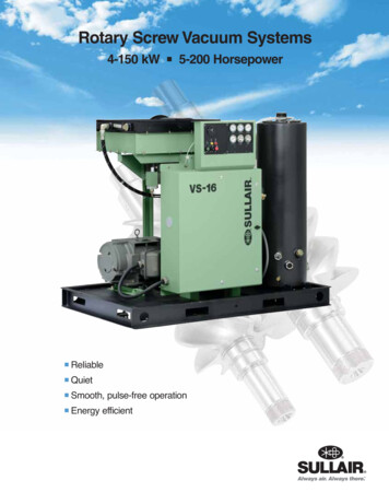
Intended use3.2Dometic Vacuum Status Control Panel“Full tank” indicatorWhen connected to a “full tank” sensor (see wiring schematics, pp. 8-9), a steady illuminated red lightcan indicate that the holding tank is full. (fig. 3 B, page 2).The VacuFlush toilet should not beoperated until the hoiding tank is emptied and the green light turns on.3.3Vacuum system controlDuring the night or other extended periods of non-use, the toilet system’s vacuum level may slowlydissipate and cause the vacuum pump to operate. To avoid this, switch the VacuFlush system power to“off” (fig. 3 C, page 2).3.4FeaturesContinuous vacuum level monitoring. Indicates when VacuFlush toilet is ready to flush.Vacuum system protection. Magnetic circuit breaker protects pump from damage.Power indicator for toilet system. Indicates when toilet system power is off or loss of electricalpower.12 or 24 V DC operation.4ComponentsRef(fig. 1 , page 2)Description1DVS02 panel cover2Mounting frame3#6 fastener4Circuit housing5Specifications5.1MaterialsPanel frame and mounting frame: ABSCircuit housing: High-density polyethylenePanel surface: Polycarbonate resin5.2ElectricalCurrent and wattage per indicator light12 V DC24 V DCAmps0.012 - 0.0160.012 - 0.016Watts0.15 - 0.220.29 - 0.45Circuit breaker – magnetic, manual resetSIZEF.L. ampsTrip amps10 amps1013.55 amps56.75Specifications subject to change without notice.6NoteBe sure circuit breaker size of DVS02panel matches VacuFlush system powerrequirements. Refer to wiringschematics, pp. 8-9.
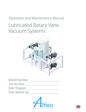
Dometic Vacuum Status Control Panel5.3Dimensions (fig. 2 , page 2)Ref.5.4SpecificationsDimensionA83 mm / 3.25 in.B83 mm / 3.25 in.C51 mm / 2 in. clearance behind wallD10 mm / 0.38 in.ApprovalsISO 8846; EMC Directive 2004/108/EC; CE approved for electromagnetic compatibility6Installation6.1Vacuum status control panel (fig. 1 A, page 2)Caution!Do not install DVS02 panel in area with potentially flammable or explosive vapors.DVS02 Panel Template1. Select panel location away from direct contact with waterDimensions (fig. 4 , page 3)and oil.2. Confirm clearance for wire connections behind wall, hullRef.Dimensionliner or bulkhead.3. Using control panel template (fig. 4 , p. 3), cut out panelA83 mm / 3.25 in.access hole (E, F) and drill fastener holes (G).4. With electrical power off, route 14-gauge stranded copperB83 mm / 3.25 in.wire (or other wire according to ABYC standards) fromC67 mm / 2.63 in.power source to panel location. Route additional wireaccording to appropriate wiring diagram (fig. 5 - 7 ,D67 mm / 2.63 in.pp. 8 - 9 – wiring diagram schematics), depending on yourapplication, to panel location. Make sure wires extend outE55 mm / 2.16 in.through access hole.5. Make proper wiring connections to wires extending fromF68 mm / 2.69 in.bottom of circuit housing (fig. 1 4, p. 2).G2 mm / 0.10 in. dia.6. Remove panel cover (fig. 1 1, p. 2) from circuit panel/mounting frame assembly (2, 4), if necessary, by carefullyHCut-out area.pulling them apart.Allow 51 mm / 2 in.7. Install mounting frame to wall with four fasteners (fig. 1 3,clearance behindwall.p.2).8. Push panel cover onto mounting frame until it locks.9. Turn on electrical power to DVS02 panel. Turn on DVS02 power switch (fig. 3 B, p. 2) andconfirm normal operation of status lights.7
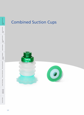
Installation6.258Dometic Vacuum Status Control PanelDVS02 system wiring schematicsDVS02 panel with vacuum generator
Dometic Vacuum Status Control Panel6DVS02 panel with vacuum tank and vacuum pump7DVS02 panel with vacuum holding tank (VHT)Installation9
OperationDometic Vacuum Status Control Panel7Operation7.1Vacuum status monitor (fig. 3 , page 2)1. When power switch is turned ON, the green light indicates that there is sufficient vacuum in theVacuFlush system to flush the toilet (A).2. When power switch is turned ON and the red light glows, this indicates that there is NOT sufficientvacuum in the system to flush the toilet (B). Do not flush toilet, or blockage may occur in system.NotesIf green and red light constantly cycle on and off between flushes, there is a possiblevacuum leak in the system. (An idle VacuFlush system should not cycle more frequentlythan once every three hours.)If green light is ON but there is no vacuum in system, a blockage has likely occurredbetween the toilet and vacuum tank. Open flush ball in toilet bowl and use standard toiletplunger to unblock.After a period of time, if red light seems to remain lit longer than when toilet system wasnew, duckbill valves in vacuum pump may require replacement.Caution!If DVS02 is connected to a “full tank” sensor and holding tank is empty, a continuous redlight may indicate extensive vacuum loss due to blockage, pump failure or leak. Turn offvacuum system and repair as soon as possible.7.2“Full tank” monitor (only when connected to “full tank” sensor in waste holding tank)1. When power switch is turned ON, the red light glows, and the vacuum pump is not running, thisindicates that the holding tank is full and needs to be pumped out. Do not flush toilet, or blockagemay occur in system.7.3Circuit breaker control (fig. 3 , page 2)1. Turn the power switch to the ON position (A, B) for normal toilet operation. One light will always be litto indicate there is power to the VacuFlush toilet system. Allow system vacuum to fully recharge andgreen light to illuminate before turning power OFF for any reason.2. During the night or other extended periods when the toilet or vacuum system is not needed tooperate, turn the power switch to the OFF position (C).10
Dometic Vacuum Status Control Panel8WarrantyWarranty and product liabilityNorth AmericaManufacturer’s One-Year Limited WarrantyDometic Corporation, Sanitation Division (Dometic) warrants to the original purchaser only that thisproduct, if used for personal, family or household purposes, is free from defects in material andworkmanship for a period of one year from the date of purchase.If this Dometic product is placed in commercial or business use, it will be warranted to the originalpurchaser only to be free of defects in material and workmanship for a period of ninety (90) daysfrom the date of purchase.Dometic reserves the right to replace or repair any part of this product that proves, upon inspectionby Dometic, to be defective in material or workmanship. All labor and transportation costs orcharges incidental to warranty service are to be borne by the purchaser-user.EXCLUSIONSIN NO EVENT SHALL DOMETIC BE LIABLE FOR INCIDENTAL OR CONSEQUENTIAL DAMAGES,FOR DAMAGES RESULTING FROM IMPROPER INSTALLATION, OR FOR DAMAGES CAUSEDBY NEGLECT, ABUSE, ALTERATION OR USE OF UNAUTHORIZED COMPONENTS. ALL IMPLIEDWARRANTIES, INCLUDING ANY IMPLIED WARRANTY OF MERCHANTABILITY OR FITNESS FORANY PARTICULAR PURPOSE, ARE LIMITED TO A PERIOD OF ONE YEAR FROM DATE OFPURCHASE.IMPLIED WARRANTIESNo person is authorized to change, add to, or create any warranty or obligation other than that setforth herein. Implied warranties, including those of merchantability and fitness for a particularpurpose, are limited to one (1) year from the date of purchase for products used for personal, familyor household purposes, and ninety (90) days from the date of purchase for products placed incommercial or business use.OTHER RIGHTSSome states do not allow limitations on the duration of an implied warranty and some states do notallow exclusions or limitations regarding incidental or consequential damages; so, the above limitations may not apply to you. This warranty gives you specific legal rights, and you may have otherrights which vary from state to state.To obtain warranty service, first contact your local dealer from whom you purchased this product orgo to Support/ for a dealer near you.Europe:Warranty and Customer ServiceWarranty arrangements are in accordance with EC Directive 44/1999/CE and the normal conditionsapplicable for the country concerned. For warranty or other service, please contact our DometicService department listed elsewhere in this manual. Any damage due to improper use is not coveredby the warranty.The warranty does not cover any modifications to the product or the use of non-original Dometicparts; the warranty does not apply if the installation and operating instructions are not adhered toand no liability shall be entertained.(continued on next page)11
WarrantyDometic Vacuum Status Control PanelProduct LiabilityProduct liability of Dometic Group and its subsidiary companies does not include damages whichmay arise from: faulty operation; improper alterations or intervention in the equipment; adverseeffects from the environment which may impact the equipment itself or the direct vicinity of theequipment or persons in the area.To obtain warranty service, first contact your local dealer from whom you purchased this product orgo to http://www.dometic.com to locate a dealer near you.9Customer serviceThere is a strong, worldwide network to assist in servicing and maintaining your toilet system. Forthe Authorized Service Center near you, please call from 8:00 a.m. to 5:00 p.m. (ET)Monday through Friday.You may also contact or have your local dealer contact the Parts Distributor nearest you for quickresponse to your replacement parts needs. They carry a complete inventory for the Dometic S.A. and .A. and CanadaInternationalWeb n.comDometic is a customer-driven, world-leading providerof leisure products for the RV, automotive, truckand marine markets. We supply the industry andaftermarket with a complete range of air conditioners,refrigerators, awnings, cookers, sanitation systems,lighting, mobile power equipment, comfort and safetysolutions, windows, doors and other equipment thatmake life more comfortable away from home.Dometic supplies a wide range of workshopequipment for service and maintenance of built-inair conditioners. Dometic also provides speciallydesigned refrigerators for hotel rooms, offices,wine storage and transport and storage of medicalproducts.Our products are sold in almost 100 countries and areproduced mainly in wholly-owned production facilitiesaround the world.REVISION AForm No. 600346523 8/17 2017 Dometic Corporation12Dometic Corporation, Sanitation Division13128 State Rt. 226, P.O. Box 38Big Prairie, OH 44611 USA1-800-321-9886 Fax: 330-496-3097www.Dometic.com
Operation Dometic Vacuum Status Control Panel 7 Operation 7.1 Vacuum status monitor (fig . 3 , page 2) 1 . When power switch is turned ON, the green light indicates that there is sufficient vacuum in the VacuFlush system to flush the toilet (A) . 2 . When power switch is turned ON and the red light glows, this indicates that there is NOT .