Transcription
Operation and Maintenance ManualLubricated Rotary VaneVacuum SystemsModel Number:Job Number:Date Shipped:Date Started Up:w w w . a m i c o . c o m
IntroductionFor further technical assistance, service or replacement parts, please contact:Amico Source Corporation85 Fulton WayRichmond Hill, ONL4B 2N4 CanadaToll Free Tel: 1.877.462.6426Toll Free Fax: 1.866.440.4986Tel: 905 764 0800Fax: 905 764 0862For Technical Support: as-techsupport@amico.comFor Parts: as-parts@amico.comPlease include the system’s job number located on the control panel with all inquires.Amico Source Corporation reserves the right to make changes and improvements to update products withoutnotice or obligation.2Amico Source Corporation
Table of ContentsSafety PrecautionsGeneral InformationInstallation and CommissioningPipingWiringControl PanelPrinciples of OperationMaintenanceControl Panel TroubleshootingPump TroubleshootingReplacement PartsWarrantyMaintenance 7www.amico.com3
Safety PrecautionsThe high vacuum levels produced from the system may cause personnel injury or property damage if the unit isimproperly operated or maintained.Operator should have carefully read and become familiar with the contents of this manual before installing,wiring, starting, operating, adjusting and maintaining the system.Operator is expected to use common sense safety precautions, good workmanship practices and follow anyrelated local safety precautions.In Addition: Before starting any installation or maintenance procedures, disconnect all power to the package. All electrical procedures must be in compliance with all national, state and local codes andrequirements. A certified electrician should connect all wiring. Refer to the electrical wiring diagram provided with the unit before starting any installation ormaintenance work. Release all vacuum from the package before removing, loosening or servicing any covers, guards,fittings, connections or other devices. Notify appropriate hospital personnel if repairs or maintenance will affect available vacuum levels. Vacuum discharge must be placed away from any intake to the facility in accordance with NFPA 99. Prior to using the Amico Medical Vacuum System, the medical facility must have a Certifier perform allinstallation tests as specified in NFPA 99. The medical facility is also responsible for ensuring that themedical vacuum meets the minimum requirements as specified in NFPA 99. This is a high speed, rotating piece of machinery. Do not attempt to service any part while themachine is in operation. To prevent automatic starting, disconnect all electrical power before performing any maintenance. Do not operate unit without belt guards, shields or screens in place. Make sure that all loose articles, packing material and tools are clear of the package. Check all safety devices periodically for proper operation. Never operate a compressor with its isolation (shutoff) valve closed or discharge pipe blocked.Damage to the pump may occur. The “Hand” mode of operation should only be used for emergencies such as a PLC malfunction andshould not be used for normal operation. Electrical service must be the same as specified on the control panel nameplate or damage to theequipment may occur. Vibration during shipment can loosen electrical terminals, fuse inserts and mechanical connections.Tighten as necessary.4Amico Source Corporation
General InformationProduct DescriptionThe vacuum system is intended for either: Medical use for patients Waste anesthetic gas disposal (WAGD)* Labs*For WAGD operation, Amico Source Corporation suggests an oxygen assured pump. Please contact AmicoSource Corporation for more information.The Amico Medical Vacuum System is designed according to the specifications agreed upon during the designphase. Changing the intended use is permissible only after prior consultation with Amico Source Corporation.Suggested operating temperature: 78 F (26 C).The vacuum system is intended for use indoors unless otherwise specified.The vacuum system is designed according to local regulations.Principles of OperationThe vacuum system takes air from the inlet. The air is passed through an inlet filter (optional) to prevent solidmatter from entering the vacuum system. The vacuum pump draws air from the system and from the receivertank. This allows the system to produce a more stable vacuum level and prevents multiple starting and stoppingof the pump(s).All parts of the system are designed to be isolated including the pump(s) and tank(s). This ensures the continuityof medical vacuum for the patients connected to the system.TransportThe system is split and crated according to specifications. Amico will make every attempt to split the system intoas few pieces as possible to consolidate shipping.www.amico.com5
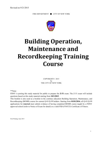
Installation and CommissioningInspection Upon ReceiptThe condition of the Amico Medical Vacuum System should be carefully inspected upon delivery. Anyindication of damage by the carrier should be noted on the delivery receipt, especially if the system will not beimmediately uncrated and installed.Amico Source Corporation modules may remain in their shipping containers until ready to be installed. If any ofthe modules are to be stored prior to installation, they must be protected from the elements to prevent rust anddeterioration.DO NOT REMOVE the protective covers from the inlet and discharge connection ports of the modules until theyare ready for connecting to the facility's pipeline distribution system.Handling!WARNING: USE APPROPRIATE LOAD RATED LIFTING EQUIPMENT AND OBSERVE SAFE LIFTINGPROCEDURES DURING ALL MOVES.The vacuum system can be moved with either a forklift or a standard pallet jack (for modular systems).Walk along the route the unit must travel and note dimensions of doorways and low ceilings. Units shouldbe placed to ensure easy access to perform maintenance and high visibility of indicators and gauges. Wheninstalling a modular system, there is no preferred arrangement of modules. The modular design of thecomponents allows for the system to be custom fit to the facility to optimize accessibility and operation.Installation Prerequisites!WARNING: All vacuum systems should be commissioned by an authorized Amico representative. Failureto do so will void all warranties on the system.Ensure that the site where the system will be installed has a source of electrical power and that power is of thecorrect electrical specification as per the design of the system.Mounting Position and SpaceFor maintenance and ventilation of the system, it is recommended that there is 2' (60.96 cm) of clearancearound the system and 3' (91.44 cm) of clearance in front of the control panel. Vibration pads are provided forthe system to reduce noise caused by the vibration of the system. The system should be leveled and placed on aconcrete pad that is suitable to sustain the weight of the system.The area should have an average ambient temperature of 70 F (21 C) with a minimum ambient temperature of40 F (4.4 C) and a maximum ambient temperature of 100 F (37.8 C).Sound levels of 76 to 85 dbA are to be anticipated. Though the sound levels are not excessive, they should beconsidered when choosing the installation location for the system.6Amico Source Corporation
Installation and Commissioning24 in[0.61 m]24 in[0.61 m]36 in[0.92 m]24 in[0.61 m]MINIMUMFORminimumclearance CLEARANCEfor maintenance andventilationMAINTENANCE & VENTILATIONPRIVATE AND CONFIDENTIALMODEL #: V-RVL-D-120P-SS-N-075-MDESCRIPTION: ROTARY VANE - LUBRICATED DUPLEX STACK MOUNTED VACUUM SYSTEMCLEARANCE DRAWING - MINIMUM CLEARANCE FOR MAINTENANCE & VENTILATIONTHIS PRINT IS PROPERTY OF AMICO SOURCE AND ISLOANED IN CONFIDENCE SUBJECT TO RETURN UPONREQUEST AND WITH THE UNDERSTANDING THAT NO JOB #: Q17590COPIES ARE TO ME MADE WITHOUT THE CONSENT OFAMICO SOURCE. ALL RIGHTS TO DESIGN OR INVENTION FINISH: ARE RESERVED.DRAWN BY: JC & PGDATE: NOV/03/15SHEET: 1 OF 1UNLESS SPECIFIED:ALL DIMENSIONS IN INCHESSURFACE FINISH 63 uinBREAK ALL EDGES 0.005-0.010REMOVE SHARP EDGES AND BURRSANGLE TOLERANCE 1 DECIMAL TOLERANCES:X.XXX.XXXX.XXXXwww.amico.com .05 .005 .00057
PipingBelow is a summary of the requirements for the medical vacuum system exhaust locations.1. Locate the medical vacuum exhaust outdoors in a manner that will minimize the hazards of noise andcontamination to the hospital and its environment. The exhaust shall be located remote from any door,window, air intake or other openings in buildings with particular attention given to separate levelsof intake and discharge. Care shall also be exercised to avoid discharge locations contraindicated byprevailing winds, adjacent buildings, topography and other influences. Outdoor exhausts shall beprotected against entry of insects, vermin, debris or precipitation. Exhaust lines shall be sized to minimizeback pressure. Discharge piping shall be free of dips or loops that might trap condensate or oil. If suchdischarge piping is unavoidable, a trapping drip leg shall be installed to keep the piping free of fluidbuildup. The exhaust shall be located at least 30 ft (10 m) from any door or operable window, 50 ft (15 m)from any mechanical air intake and a minimum of 10 ft (3 m) above grade.2. Medical vacuum exhausts for separate pumps shall be permitted to be joined together to one commonexhaust, provided such intake is appropriately sized.3. Discharge of pumps utilizing a common exhaust pipe shall be fitted with a check valve or a manual value(locked open) or arranged to permit capping of the active pipe when removing or servicing the pump.4. Install a drip leg at the base of each pump exhaust line riser.5. Minimum exhaust pipe sizing required based on the medical vacuum system horsepower, configurationand the total pipe length (including elbows and tees) in the medical vacuum exhaust line.a. The medical vacuum exhausts are joined together to one common exhaust.b. Minimum pipe size must be maintained for the total length of exhaust pipe.c. Use the next larger size pipe in the event the minimum size is not available.To ensure that no restriction of airflow (and thus back pressure) occurs in the exhaust line, size the pipingaccording to the table on the next page.8Amico Source Corporation
PipingExhaust Pipe SizingUnitFlow BasisAllowable Equivalent Run (Feet)SCFM@19" hgMinimum Nominal Pipe Size:1.5"2.0"2.5"3.0"4.0"5.0"6.0"8.0"Duplex 1.5 Hp12450Duplex 2 Hp20170700Duplex 3 Hp3665250800Duplex 5 Hp741665200475Duplex 7.5 Hp138601506001,900Duplex 10 Hp178451004251,200Duplex 15 Hp240552256751,600Duplex 20 Hp272451805251,300Duplex 25 Hp33625110325800Triplex 5 Hp113225900Triplex 7.5 Hp20775300900Triplex 10 Hp267451805501,400Triplex 15 Hp375100300700Triplex 20 Hp40980250600Triplex 25 Hp50460175425Quad 7.5 Hp2751905501,400Quad 10 Hp355110325800Quad 15 Hp47865190450Quad 20 Hp54250150350Quad 25 Hp67035170425305045Fittings Equivalent LengthsMinimum Nominal Pipe 2.5'3.0'4.0'5.5'7.0'12.5'16.0'19.0'Tee '/1.5'34'/2'www.amico.com9
Wiring!WARNING: BE SURE TO DISCONNECT ALL ELECTRICAL POWER FROM THE SYSTEM BEFORE PERFORMINGANY ELECTRICAL PROCEDURES.Refer to the electrical diagram provided with the unit before starting any installation or maintenance work.Do not operate system on a voltage other than the voltage specified on the system panel.All customer wiring should be in compliance with the National Electrical Code and any other applicable state orlocal codes.!CAUTION: All voltages will be disconnected from the pump modules using the circuit breaker. Openingthe appropriate fused knife-switch disconnects control power. Turning off the appropriate motor circuitbreaker disconnects motor power.Refer to the wiring diagram(s) that came with the pumps for pertinent wiring connections.Check the control voltage, phase and amp ratings before starting the electrical installation and make sure thevoltage supplied by the hospital is the same. The wire size should be able to handle peak motor amp load of alloperating units. Refer to the specifications for full load and compressor system amperes on the wiring diagram.Check all electrical connections within the vacuum system that may have loosened during shipment.Only qualified electricians should make power connections to the control panel and any interconnecting wiring.Ensure that the electrical supply for the emergency generation system is consistent with the vacuum system’srequirements.Three-phase power supplied from emergency generator(s) must match that of the normal supply to allow forcorrect motor rotation direction at all times.Control PanelSystem OverviewThe Premium series controllers are based on vacuum transducers. Every controller will have a color touch screen(HMI) that will allow for process variables adjustment; alarm set points adjustment; visual indication of systemfaults; current vacuum level as well as each pump status including pump faults, pump duty in sequence andelapsed run time. All pumps will have a circuit breaker through the door disconnect and illuminated H-O-Aswitches.10Amico Source Corporation
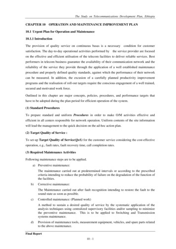
Control PanelControllers are factory wired for a single power source and a powerdistribution block is provided for power connection. The systemwill accept separate power feeds for each pump in case the powerdistribution block is removed for redundancy purposes. A minimumof two control transformers will be provided. In case the primarytransformer fails, a secondary transformer automatically providescontrol power. Power switching relay(s) are provided to switchprimary transformer windings to any available power source ifseparate power feeds are used.717425336Sequence of OperationOperation of the controller is based on “ON” and “OFF” setpoints.(See “Setpoints Adjustment” for instructions on how to adjustsetpoints).The lead pump will switch on when vacuum level drops below the“ON” setpoint and shuts off when vacuum level reaches the “OFF”setpoint. Every time the lead setpoint is satisfied, the next availablepump will become the lead pump.Lag and all reserve pumps (if applicable) will switch on when thevacuum level drops below the respective “ON” setpoints and willswitch off when respective “OFF” setpoints are reached.Note: See “System timers” for additional information on pumpsequencing).If a pump is switched off by an H-O-A switch or a pump fault isdetected, it will be automatically taken out of the sequence andits duty transferred to the next available pump. Once the fault iscleared (See “Troubleshooting” for additional information) and theH-O-A switch is in the “A” position, the pump will be automatically included into the sequence.1. Display Screen – Displays the systems operating screens, available in Pro IEC or ECO displays2. Touch Monitor – For changing different settings on the display screen3. H-O-A Selector Switch – Pump control switch: Hand/Off/Auto4. Alarm Horn – Sounds when an alarm condition occurs5. Alarm Silence – Silences alarm to allow work to be performed without the annoyance of the alarm6. Alarm Reset – Resets all alarm states after the condition that set off the alarm is corrected; do not resetthe alarm until the type of alarm has been recorded and the alarm cause identified and corrected to thebest of your ability7. Power Breaker – Controls the power to each pump and the control panelwww.amico.com11
Control PanelMain ScreenVacuum (inHg)0.0P1P2P3P4P5P6HomeSystem StatusDutyLEADRES. 1RES. 2RES. ,00400,00400,00400,004ServiceSetupPro IEC Display ScreenVACUUMinHq0.0HOMESYSTEMOKP1P2P3INFOLEADRES. 1RES. 200,00400,00400,004SERVICESET UPECO Display ScreenPump DutyDisplays the following: If H-O-A switch is in the “O” (OFF) position, it will read “OFF” If pump is running, it will read “RUN” regardless of the H-O-A position If pump is off and the H-O-A switch is in “A” (AUTO) position, it will read the duty of the pump: LEAD,LAG, RES1 (RESERVE 1), RES2 (RESERVE 2) as applicable If a pump is in critical fault, it will read “OUT OF SERVICE”Pump StatusDisplays the following: If a pump is in critical fault and the H-O-A switch is in “A” (AUTO) position, it will read “FAULT”Note: even if the reason for the fault is cleared (e.g. an “OVERTEMP” alarm is cleared and reset), thestatus of the pump will remain in “FAULT.” To reset pump status, the respective H-O-A switch must beturned to “O” (OFF) position. (See “Troubleshooting”for additional information) If a pump is in non-critical fault (e.g. maintenance is suggested), it will read “ATTENTION REQUIRED!” If a pump is in normal operating condition, it will read “OK”Run Time Display Run time for each pump is displayed in HoursVacuum Display Current vacuum is displayed in inHg In case the pressure transducer fails, all pumps will shut off and “SENSOR FAILED” will be displayedinstead of the pressure readout. After the sensor is repaired, push the reset button to reset sensorfault. (See “Troubleshooting” for additional information)12Amico Source Corporation
Control PanelSystem Status Display If no system faults are present, it will read “OK.” If any unit alarms are present, it will read “FAULT! CLICKHERE.” By clicking on the message, a unit alarms screen will be displayed where specific alarms can beviewed. (See “Troubleshooting” for additional information)Pump Detail ScreenNext Service Hours500TemperatureAlarms and AlertsNormalOKHRS. TO SRVCE500TEMPERATURENORMALP1P2P3P4P5P6Home Detail Detail Detail Detail Detail DetailPro IEC Display ScreenHOMEP1DETLP2DETLP3DETLECO Display ScreenThe Pump Detail screen can be accessed from the main screen by pressing the respective “P #” button. It willdisplay the current pump status, hours left until service is required, the temperature readout for each head ifRTD sensors are used, pump faults and alarms (See “Troubleshooting” for additional information).Returning to the Home ScreenFrom any subscreen, you can press the “Home” button or “Exit” to return to the Home screen.www.amico.com13
Control PanelSetpoints ScreenLead OninHgLag OninHgRes. 1 OninHgRes. 2 OninHgRes. 3 OninHgRes. 4 OninHgHome0.000.000.000.000.000.00Lead OffinHgLag OffinHgRes. 1 OffinHgRes. 2 OffinHgRes. 3 OffinHgRes. 4 OffinHg0.000.000.000.000.000.00SetSystem Units SystemAirPoints Timers Alarms Config MonitorLEAD ONinHgRES1 ONinHgRES2 ONinHgSETHOME PNTSLEAD OFFinHgRES1 OFF0.00inHgRES2 OFF0.00inHgSYS UNITS SYSTMRS ALRMS CNFG0.000.000.000.00AIRMNTRECO Display ScreenPro IEC Display ScreenThe vacuum level setpoints screen can be accessed from the main screen by pressing the “SET UP” button. “ON”and “OFF” setpoints can be adjusted by pressing the respective values. A numeric keypad will appear, allowingdirect value entry.Note: The system has the following restrictions: It will not accept “OFF” entry values lower than “ON” values Lag and all subsequent Res. (if applicable) “ON” and “OFF” values cannot be higher than previous “ON”and “OFF” valuesSystem Timers ScreenMin. Run.Time Sec.0 – Not Used360Forced Alt.Time Min.0 – Not Used15LoadTime Sec.0 – Not Used0HomeForced Run.Time Sec.0 – Not Used0MIN. RUNSEC., 0–N/UUnloadTime Sec.0 – Not Used0SetSystem Units SystemAirPoints Timers Alarms Config MonitorPro IEC Display ScreenLOAD TMRSEC., 0–N/USETHOME PNTSFORCED RUNSEC., 0–N/UFORCED ALT.15MIN., 0-N/UUNLOAD TMR0SEC., 0–N/USYS UNITS SYSTMRS ALRMS CNFG36000AIRMNTRECO Display ScreenThe System Timers screen can be accessed from the main screen by pressing the “Set Up” button and thenpressing “System Timers.” It will display the minimum run timer, forced run timer, forced alternation timer andload/unload timers.14Amico Source Corporation
Control PanelMinimum Run TimerThe value of this timer is in seconds. This is the time that the pump will run after it has been switched on inautomatic mode regardless of vacuum level. For example, if it is set to 600 seconds (10 minutes) and a respectivevacuum setpoint is satisfied in 5 minutes, the pump will run for 5 more minutes and then shut down. If arespective vacuum setpoint is satisfied in 13 minutes, the pump will shut down immediately upon switchsatisfaction. The value “0” will turn this timer off.!WARNING: ALL VACUUM SYSTEMS SHOULD HAVE THIS SET TO A MINIMUM OF 360 SECONDS. FAILURETO DO SO WILL VOID THE WARRANTY.Forced Run TimerThe value of this timer is in minutes. This is the time that will take to switch the next available pump on if thelead setpoint (SP1) is not satisfied within this period. For example, if it is set to 15 minutes and the lead vacuumsetpoint is not satisfied within this time with the lead pump running, then the lag pump will be switched on. Ifthe lead setpoint is still not satisfied within the next 15 minutes, the reserve pump (if applicable) will be switchedon. All pumps will run until the lead setpoint is satisfied. If a minimum run timer is used (see “Minimum RunTimer” section above), pumps that ran less than the minimum run timer setting will continue to run until theirminimum run time elapses. The value “0” will turn this feature off.Note: If lag and reserve (if applicable) pumps are switched on by their respective vacuum setpoint, they willcontinue to run until the lead setpoint is satisfiedForced Alternation TimerThe value of this timer is in minutes. This is the time that will take to alternate the pumps in case the leadsetpoint was not satisfied within the specified time period. For example, if this timer is set to 480 minutes (8hours) and the lead setpoint is not satisfied within this period, all pumps will be shut off briefly and the next leadpump will be switched on. The value “0” will turn this feature off.Note: Even with this timer active, normal alternation on each cycle will occur.www.amico.com15
Control PanelAlarms Setpoint ScreenHomeVacuum UnitsinHgLow Vacuum inHg12.00VACUUM inHgUNITSLOW VACinHg 12.00SETSYS UNITS SYSHOME PNTSTMRS ALRMS CNFGPanelEmailSetupSetSystem Units SystemAirPoints Timers Alarms Config MonitorAIRMNTRECO Display ScreenPro IEC Display ScreenThis screen can be accessed from the main screen by pressing the “SET UP” button and then pressing “ALARMS.”It allows entering settings for the following alarms:Overtemp AlarmThis alarm setpoint is available if the system is based on RTD temperature sensors to monitor the pump headtemperature. If the system uses temperature switches instead, this setpoint is not available. The setpoint is in For C. That can be toggled by pressing the Temperature Units value field. Up/Down arrows will appear and youcan use these to switch between units of measure. Press “ENTER” to confirm. Touch the Overtemp Alarm valuefield so that a numeric keypad appears to allow direct value entry.System Log ScreenDateTimeState16/02/25LAG IN USE!16/02/25DP ERROR!16/03/07DP ERROR!16/03/07LAG IN 2RTNHomeSystemStatusSystemLogPro IEC Display ScreenThe System Log keeps track of all of the alarms on the system. The information provided in the log can be usedfor troubleshooting purposes.16Amico Source Corporation
Control PanelSystem Information ScreenEquipment InfoModel:Pumps:Rec. #Serial Number:460Volts:6Phase:3HP:15PUMPS:3S/N:460PHASE: 3REC.#:VOLTS:HomeHOMESystem SystemInfoEditHP: 15.00SYSTEM SYSTEMINFOEDITECO Display ScreenPro IEC Display ScreenThis screen can be accessed from the main screen by pressing the “System Info” button. It will display generalsystem information.Service Information ScreenAmico Source CorporationService Provider:Amico Source 1.877.462.6426Service Interval Hours:500Service Parts InfoSERVICEPROVIDER:AMICO SOURCE1-877-462-6426SERVICE INTERVAL, HRS:HomeServiceInfoServiceEditPro IEC Display ScreenHOMESRVCEINFO500SRVCEEDITECO Display ScreenThe Service Information screen can be accessed from the main screen by pressing the “System Info” button andthen pressing “Service Info” or by pressing on the “Service Needed” message if it has appeared. It will display theservice provider’s information, maintenance interval and other service information.www.amico.com17
Principles of OperationThe Amico Source Corporation Lubricated Rotary Vane pumps are direct driven, air cooled, oil-sealed, rotaryvane pumps that operate as positive displacement pumps. They consist of a rotor positioned eccentrically in acylindrical stator. The rotor has three radially sliding vanes which divide the pump chamber into three segments.The gas to be pumped enters at the inlet port, passes through the inlet screen and the open anti-suck-backvalve into the pump chamber. As the rotor rotates, the inlet aperture is closed and then the gas is compressedand forced out through the exhaust port. This operation is repeated three times per revolution.The following are recommendations provided by the vacuum pump manufacturer. For a more detailed manual,please contact Amico Source Corporation for a copy of the pump manual directly from the manufacturer.Vacuum Level SettingSystem Vacuum Factory SettingStartStopLead18 inHg23 inHgRes 116 inHg21 inHgRes 214 inHg19 inHgRes 312 inHg17 inHgFor maintenance or other reasons, the pumps can operate in the “Hand” position. In this condition, the pumpin the “Hand” position will start when the switch remains in hand and will continue to run until the switch isin “Off” or “Auto” position. These vacuum level conditions must be programmed in the control panel. Thesevacuum level values must be set to ensure safe operation of the pumps.For high altitude installations, pumps may not be able to meet these vacuum levels. If the pump runs and isunable to meet these settings, please contact Amico Source Corporation’s Technical Support for assistance.18Amico Source Corporation
MaintenanceVacuum Pump!WARNING: BEFORE STARTING ANY MAINTENANCE PROCEDURES, DISCONNECT ALL POWER TO THEPACKAGERelease all vacuum from the package before removing, loosening, or servicing any covers, guards, fittings,connections, or other devices.Never perform any maintenance functions while the unit is in operation.Maintenance and Inspection Time IntervalComponentInspectionInstructionsEnclosure ofpumpClear surrounding ofdustOil levelCheck that the levelis slightly above themiddle of the sightglass and free ofcontamination.Exhaust filterReplace as per planInspectFan cowlingClear of dustInspectFan wheelClear of dustInspectVentilationgrillesClear of dustInspectCooling fanClear of dustInspectDailyInspectEvery 500 Hoursor 3 monthsEvery 1,000 Hoursor 3 monthsEvery 5,000 Hoursor 1 YearInspectInspectInspectRemarksChange with oilfilterChangeReplaceOr as necessarywww.amico.com19
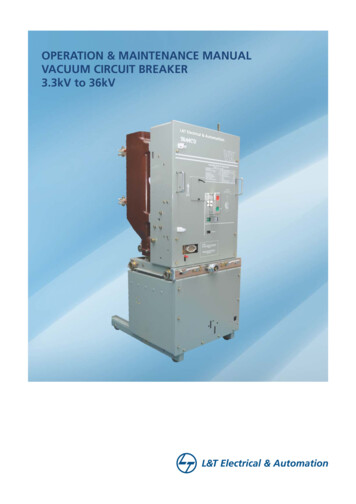
Control Panel TroubleshootingTo Begin troubleshooting the system, press the System Status button which reads “FAULT! CLICK HERE” or"SYSTEM FAULT!".Vacuum (inHg)System Status0.0CLICK HEREFAULT!DutyP1P2P3P4P5P6OUT OFSERVICELAGRUNRUNOFFOFFHomeInfoStatusHoursFAULT 00,004ATTENTION00,004REQUIRED!OK 00,004OK 00,004OK 00,004OK 2P3INFOFAULTRUNOFF00,004SERVICE00,004SERVICESET UPECO Display ScreenPro IEC Display ScreenYou will get a screen like the one shown below:PRESSURESENSORFAILED!LAGIN ILED!LAGIN USE!LEADSELECTAUTOVACUUMLOW!HomeSystemStatusPro IEC Display Screen20Amico Source CorporationHOME SYSTEMSTATUSECO Display ScreenDRYERCONTROL
Control Panel TroubleshootingProblemPossible CausesSolutionPressure sensor failed Loose Wire Check the wiring between thesensor and terminal in the panel“ERROR” in place of pressurereadout Pressure sensor is faulty Replace pressure sensorLag in use Last available pump is called One of the pumps may be out ofservice Confirm all pumps are working onautomatic Once at least one of the pumpsis turned off automatically in thesystem, press alarm reset Investigate the demand from thefacilityPrimary transformer failed Transformer failure Burned out fuse Contact certified technicianReceiver high water(Québec systems only) CSA vacuum systems in Québec only High water level in receiver tank Check receiver tank for water Drain tank as necessary Replace sensor as necessaryPump TroubleshootingProblemPossible CausesSolutionMain power disconnectedTurn on main powerPhase reversal monitor openChange power supply phase on incomingpowerCheck voltage dial setting on phase reversalswitchFailure to startPower failurePump shuts off unexpectedlyPower failureRestore powerMain fuse blownReplace fuseFuse blown in control circuitReplace fuseOverload tripped on starterReset and check for system overloadHigh temperature switch activatedAllow unit to cool, reset switch and check forover temperature conditionVacuum switch openAdjust or replace switchLoose or faulty connectionCheck and tighten all wire connectionsMain fuse blownReplace fuseFuse blown in control circuitReplace fuseOverload tripped on starterReset and check for system overloadVacuum switch has incorrect adjustmentAdjust or replaceHigh inlet vacuum switch activatedCheck for dirty/clogged inlet filter or inletpiping restrictionHigh temperature switch activatedAllow unit to cool, reset switch and check forover temperature conditionwww.amico.com21
Pump TroubleshootingProblemHigh temperature alarmLow tank vacuumPossible CausesSolutionHigh temperature switch activatedAllow unit to cool, reset switch and check forover temperature conditionSystem piping leaksRepair leaksDefective pressure gaugeReplace gaugePressure switch openAdjust or replaceNo power to solenoid or solenoid stuck open Check electrical connectionsIntake filter cloggedClean or replaceSystem undersizedContact Amico Source CorporationIncorrect vacuum settingAdjust vacuum switchFaulty vacuum switchReplace switchSystem piping leaksRepair leaksCheck valve or the line to receiver is leakingor pluggedReplace if necessaryMinimum timer not setSet minimum t
The vacuum system takes air from the inlet. The air is passed through an inlet filter (optional) to prevent solid matter from entering the vacuum system. The vacuum pump draws air from the system and from the receiver tank. This allows the system to produce a more stable vacuum level and prevents multiple starting and stopping of the pump(s).