Transcription
Application TechniqueOriginal InstructionsCENTERLINE Low Voltage Motor Control Centers Functional SafetyBulletin Numbers 2100 and 2500
CENTERLINE Low Voltage Motor Control Centers Functional Safety Application TechniqueImportant User InformationRead this document and the documents listed in the additional resources section about installation, configuration, andoperation of this equipment before you install, configure, operate, or maintain this product. Users are required to familiarizethemselves with installation and wiring instructions in addition to requirements of all applicable codes, laws, and standards.Activities including installation, adjustments, putting into service, use, assembly, disassembly, and maintenance are required tobe carried out by suitably trained personnel in accordance with applicable code of practice.If this equipment is used in a manner not specified by the manufacturer, the protection provided by the equipment may beimpaired.In no event will Rockwell Automation, Inc. be responsible or liable for indirect or consequential damages resulting from the useor application of this equipment.The examples and diagrams in this manual are included solely for illustrative purposes. Because of the many variables andrequirements associated with any particular installation, Rockwell Automation, Inc. cannot assume responsibility or liability foractual use based on the examples and diagrams.No patent liability is assumed by Rockwell Automation, Inc. with respect to use of information, circuits, equipment, or softwaredescribed in this manual.Reproduction of the contents of this manual, in whole or in part, without written permission of Rockwell Automation, Inc., isprohibited.Throughout this manual, when necessary, we use notes to make you aware of safety considerations.WARNING: Identifies information about practices or circumstances that can cause an explosion in a hazardous environment, which maylead to personal injury or death, property damage, or economic loss.ATTENTION: Identifies information about practices or circumstances that can lead to personal injury or death, property damage, oreconomic loss. Attentions help you identify a hazard, avoid a hazard, and recognize the consequence.IMPORTANTIdentifies information that is critical for successful application and understanding of the product.Labels may also be on or inside the equipment to provide specific precautions.SHOCK HAZARD: Labels may be on or inside the equipment, for example, a drive or motor, to alert people that dangerous voltage maybe present.BURN HAZARD: Labels may be on or inside the equipment, for example, a drive or motor, to alert people that surfaces may reachdangerous temperatures.ARC FLASH HAZARD: Labels may be on or inside the equipment, for example, a motor control center, to alert people to potential ArcFlash. Arc Flash will cause severe injury or death. Wear proper Personal Protective Equipment (PPE). Follow ALL Regulatory requirementsfor safe work practices and for Personal Protective Equipment (PPE).2Rockwell Automation Publication MCC-AT007B-EN-P - February 2021
Table of ContentsPreface . . . . . . . . . . . . . . . . . . . . . . . . . . . . . . . . . . . . . . . . . . . . . . . . . . . . . . . . . . . . . . . . . . . . . . . . . 7About This Publication . . . . . . . . . . . . . . . . . . . . . . . . . . . . . . . . . . . . . . . . . . . . . . . . . . . . . . . 7Access Components of the Safety Function . . . . . . . . . . . . . . . . . . . . . . . . . . . . . . . . . . . . . . 7Related Safety Standards . . . . . . . . . . . . . . . . . . . . . . . . . . . . . . . . . . . . . . . . . . . . . . . . . . . . 8Chapter 1General Safety InformationRisk Assessments. . . . . . . . . . . . . . . . . . . . . . . . . . . . . . . . . . . . . . . . . . . . . . . . . . . . . . . . . . . 9From: Risk Assessment (ISO 12100) . . . . . . . . . . . . . . . . . . . . . . . . . . . . . . . . . . . . . . . . . 91. Identification of safety functions . . . . . . . . . . . . . . . . . . . . . . . . . . . . . . . . . . . . . . . . . 92. Specification of characteristics of each function . . . . . . . . . . . . . . . . . . . . . . . . . . . . 93. Determination of required PL (PLr) for each safety function . . . . . . . . . . . . . . . . . . . 9To: Realization and PL Evaluation . . . . . . . . . . . . . . . . . . . . . . . . . . . . . . . . . . . . . . . . . . 9Safety Distance Calculation . . . . . . . . . . . . . . . . . . . . . . . . . . . . . . . . . . . . . . . . . . . . . . . . . . 10Considerations for Safety Distance and Stopping Performance . . . . . . . . . . . . . . . . . 10Safe Stop Safety Function . . . . . . . . . . . . . . . . . . . . . . . . . . . . . . . . . . . . . . . . . . . . . . . . . . . 10Chapter 2IntroductionChapter 3Safety Variable FrequencyDrives SubsystemsVFD Safety Certification . . . . . . . . . . . . . . . . . . . . . . . . . . . . . . . . . . . . . . . . . . . . . . . . . . . . . 13PowerFlex 750-series Drive Units . . . . . . . . . . . . . . . . . . . . . . . . . . . . . . . . . . . . . . . . . . . . . 13Safety Ratings. . . . . . . . . . . . . . . . . . . . . . . . . . . . . . . . . . . . . . . . . . . . . . . . . . . . . . . . . 14Electrical Schematics Examples . . . . . . . . . . . . . . . . . . . . . . . . . . . . . . . . . . . . . . . . . . 14Configuration . . . . . . . . . . . . . . . . . . . . . . . . . . . . . . . . . . . . . . . . . . . . . . . . . . . . . . . . . 19PowerFlex 520-series Units. . . . . . . . . . . . . . . . . . . . . . . . . . . . . . . . . . . . . . . . . . . . . . . . . . 20Safety Ratings. . . . . . . . . . . . . . . . . . . . . . . . . . . . . . . . . . . . . . . . . . . . . . . . . . . . . . . . . 20Electrical Schematics Examples . . . . . . . . . . . . . . . . . . . . . . . . . . . . . . . . . . . . . . . . . . 20Configuration . . . . . . . . . . . . . . . . . . . . . . . . . . . . . . . . . . . . . . . . . . . . . . . . . . . . . . . . . 24Chapter 4Safety Starters SubsystemsFull Voltage Non-Reversing (FVNR) Starter Subsystem – Category 1/PLc . . . . . . . . . . . . . . 27Safety Rating. . . . . . . . . . . . . . . . . . . . . . . . . . . . . . . . . . . . . . . . . . . . . . . . . . . . . . . . . . 27Electrical Schematic Example using Interposing Relay . . . . . . . . . . . . . . . . . . . . . . . . 27Electrical Schematic Example without Interposing Relay. . . . . . . . . . . . . . . . . . . . . . . 28Configuration . . . . . . . . . . . . . . . . . . . . . . . . . . . . . . . . . . . . . . . . . . . . . . . . . . . . . . . . . 29Full Voltage Non-Reversing Starter Subsystem - Category 3 / PLe. . . . . . . . . . . . . . . . . . . 30Safety Rating. . . . . . . . . . . . . . . . . . . . . . . . . . . . . . . . . . . . . . . . . . . . . . . . . . . . . . . . . . 30Electrical Schematic Examples . . . . . . . . . . . . . . . . . . . . . . . . . . . . . . . . . . . . . . . . . . . 31Configuration . . . . . . . . . . . . . . . . . . . . . . . . . . . . . . . . . . . . . . . . . . . . . . . . . . . . . . . . . 36Full Voltage Reversing Starter Subsystem – Category 1/PLc . . . . . . . . . . . . . . . . . . . . . . . . 36Safety Rating. . . . . . . . . . . . . . . . . . . . . . . . . . . . . . . . . . . . . . . . . . . . . . . . . . . . . . . . . . 37Electrical Schematic using Interposing Relay . . . . . . . . . . . . . . . . . . . . . . . . . . . . . . . . 37Electrical Schematic without Interposing Relay . . . . . . . . . . . . . . . . . . . . . . . . . . . . . . 38Rockwell Automation Publication MCC-AT007B-EN-P - February 20213
Table of ContentsConfiguration . . . . . . . . . . . . . . . . . . . . . . . . . . . . . . . . . . . . . . . . . . . . . . . . . . . . . . . . . 38FVR Starter Subsystem - Category 3 / PLe . . . . . . . . . . . . . . . . . . . . . . . . . . . . . . . . . . . . . . 39Safety Rating. . . . . . . . . . . . . . . . . . . . . . . . . . . . . . . . . . . . . . . . . . . . . . . . . . . . . . . . . . 39Electrical Schematic Examples . . . . . . . . . . . . . . . . . . . . . . . . . . . . . . . . . . . . . . . . . . . 40Configuration . . . . . . . . . . . . . . . . . . . . . . . . . . . . . . . . . . . . . . . . . . . . . . . . . . . . . . . . . 46Chapter 5Safety Distribution SubsystemsSafety Relay Subsystem – Category 1 . . . . . . . . . . . . . . . . . . . . . . . . . . . . . . . . . . . . . . . . . . 47Safety Rating. . . . . . . . . . . . . . . . . . . . . . . . . . . . . . . . . . . . . . . . . . . . . . . . . . . . . . . . . . 47CENTERLINE 2100 Circuit Description . . . . . . . . . . . . . . . . . . . . . . . . . . . . . . . . . . . . . . 47Electrical Schematic Example . . . . . . . . . . . . . . . . . . . . . . . . . . . . . . . . . . . . . . . . . . . . 48Safety Monitoring Relay Distribution Subsystem – Category 3. . . . . . . . . . . . . . . . . . . . . . . 49Safety Rating. . . . . . . . . . . . . . . . . . . . . . . . . . . . . . . . . . . . . . . . . . . . . . . . . . . . . . . . . . 49CENTERLINE 2100 Circuit Description . . . . . . . . . . . . . . . . . . . . . . . . . . . . . . . . . . . . . . 49Electrical Schematic Example . . . . . . . . . . . . . . . . . . . . . . . . . . . . . . . . . . . . . . . . . . . . 50Configuration . . . . . . . . . . . . . . . . . . . . . . . . . . . . . . . . . . . . . . . . . . . . . . . . . . . . . . . . . 51Safety Remote I/O Distribution Subsystem – Category 3 . . . . . . . . . . . . . . . . . . . . . . . . . . . 52Safety Rating. . . . . . . . . . . . . . . . . . . . . . . . . . . . . . . . . . . . . . . . . . . . . . . . . . . . . . . . . . 52Standard Options . . . . . . . . . . . . . . . . . . . . . . . . . . . . . . . . . . . . . . . . . . . . . . . . . . . . . . 52Circuit Components for the Option with Interposing Relays. . . . . . . . . . . . . . . . . . . . . 52Circuit Description for the Option with Interposing Relays. . . . . . . . . . . . . . . . . . . . . . 53Configuration . . . . . . . . . . . . . . . . . . . . . . . . . . . . . . . . . . . . . . . . . . . . . . . . . . . . . . . . . 54Electrical Schematic Example . . . . . . . . . . . . . . . . . . . . . . . . . . . . . . . . . . . . . . . . . . . . 54Chapter 6Multi-motor E-stop SafetyFunction Examples4Safety Function: Multi-motor E-stop - Category 1 . . . . . . . . . . . . . . . . . . . . . . . . . . . . . . . . 57Safety Function Realization: Risk Assessment . . . . . . . . . . . . . . . . . . . . . . . . . . . . . . . 57Safety Function Requirements. . . . . . . . . . . . . . . . . . . . . . . . . . . . . . . . . . . . . . . . . . . . 57Functional Safety Description . . . . . . . . . . . . . . . . . . . . . . . . . . . . . . . . . . . . . . . . . . . . 58Bill of Material . . . . . . . . . . . . . . . . . . . . . . . . . . . . . . . . . . . . . . . . . . . . . . . . . . . . . . . . . 58Setup and Wiring . . . . . . . . . . . . . . . . . . . . . . . . . . . . . . . . . . . . . . . . . . . . . . . . . . . . . . 59Calculation of the Performance Level . . . . . . . . . . . . . . . . . . . . . . . . . . . . . . . . . . . . . . 60Verification and Validation Plan. . . . . . . . . . . . . . . . . . . . . . . . . . . . . . . . . . . . . . . . . . . 62Safety Function: Multi-motor E-stop using a Monitoring Safety Relay - Category 3 . . . . . . 62Safety Function Realization: Risk Assessment . . . . . . . . . . . . . . . . . . . . . . . . . . . . . . . 62Safety Function Requirements. . . . . . . . . . . . . . . . . . . . . . . . . . . . . . . . . . . . . . . . . . . . 62Functional Safety Description . . . . . . . . . . . . . . . . . . . . . . . . . . . . . . . . . . . . . . . . . . . . 63Bill of Material . . . . . . . . . . . . . . . . . . . . . . . . . . . . . . . . . . . . . . . . . . . . . . . . . . . . . . . . . 64Setup and Wiring . . . . . . . . . . . . . . . . . . . . . . . . . . . . . . . . . . . . . . . . . . . . . . . . . . . . . . 64Calculation of the Performance Level . . . . . . . . . . . . . . . . . . . . . . . . . . . . . . . . . . . . . . 65Verification and Validation Plan. . . . . . . . . . . . . . . . . . . . . . . . . . . . . . . . . . . . . . . . . . . 68Safety Function: Multi-motor E-stop using 1734 Remote I/O – Category 3 . . . . . . . . . . . . . 68Safety Function Realization: Risk Assessment . . . . . . . . . . . . . . . . . . . . . . . . . . . . . . . 68Safety Function Requirements. . . . . . . . . . . . . . . . . . . . . . . . . . . . . . . . . . . . . . . . . . . . 68Functional Safety Description . . . . . . . . . . . . . . . . . . . . . . . . . . . . . . . . . . . . . . . . . . . . 69Bill of Material . . . . . . . . . . . . . . . . . . . . . . . . . . . . . . . . . . . . . . . . . . . . . . . . . . . . . . . . . 70Setup and Wiring . . . . . . . . . . . . . . . . . . . . . . . . . . . . . . . . . . . . . . . . . . . . . . . . . . . . . . 71Configuration . . . . . . . . . . . . . . . . . . . . . . . . . . . . . . . . . . . . . . . . . . . . . . . . . . . . . . . . . 72Calculation of the Performance Level . . . . . . . . . . . . . . . . . . . . . . . . . . . . . . . . . . . . . . 72Rockwell Automation Publication MCC-AT007B-EN-P - February 2021
Table of ContentsVerification and Validation Plan. . . . . . . . . . . . . . . . . . . . . . . . . . . . . . . . . . . . . . . . . . .Safety Function: Multi-motor E-stop using Integrated Safety – Category 3 . . . . . . . . . . . .Safety Function Realization: Risk Assessment . . . . . . . . . . . . . . . . . . . . . . . . . . . . . . .Safety Function Requirements. . . . . . . . . . . . . . . . . . . . . . . . . . . . . . . . . . . . . . . . . . . .Functional Safety Description . . . . . . . . . . . . . . . . . . . . . . . . . . . . . . . . . . . . . . . . . . . .Bill of Material . . . . . . . . . . . . . . . . . . . . . . . . . . . . . . . . . . . . . . . . . . . . . . . . . . . . . . . . .Setup and Wiring . . . . . . . . . . . . . . . . . . . . . . . . . . . . . . . . . . . . . . . . . . . . . . . . . . . . . .Configuration . . . . . . . . . . . . . . . . . . . . . . . . . . . . . . . . . . . . . . . . . . . . . . . . . . . . . . . . .Calculation of the Performance Level . . . . . . . . . . . . . . . . . . . . . . . . . . . . . . . . . . . . . .Verification and Validation Plan. . . . . . . . . . . . . . . . . . . . . . . . . . . . . . . . . . . . . . . . . . .75757576767777787981Appendix AQuick Reference - FunctionalSafety RatingAppendix BSISTEMA CENTERLINE FileOrganizationGlossary . . . . . . . . . . . . . . . . . . . . . . . . . . . . . . . . . . . . . . . . . . . . . . . . 109Additional Resources . . . . . . . . . . . . . . . . . . . . . . . . . . . . . . . . . . . . . . 112Rockwell Automation Publication MCC-AT007B-EN-P - February 20215
Table of ContentsNotes:6Rockwell Automation Publication MCC-AT007B-EN-P - February 2021
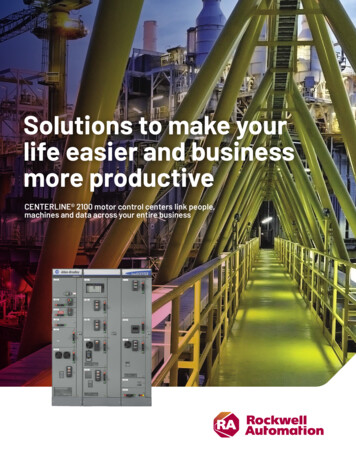
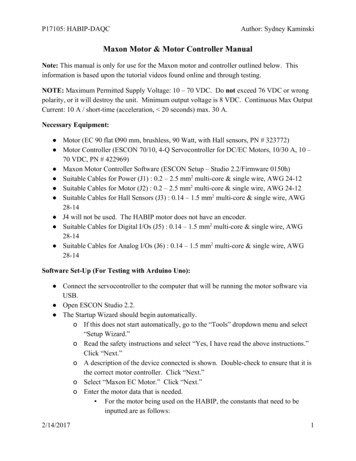
PrefaceSummary of ChangesThis publication contains the following new or updated information. This list includes substantive updates only and is not intended to reflect allchanges.TopicUpdated Figure 6 PowerFlex 753 Unit with 20-750-S Module, MSR138DP Relay, and LocalOperation (PlantPAx) Sample Wiring DiagramPage17About This PublicationThis publication describes a standardized implementation of safety functions that combine CENTERLINE Low Voltage Motor Control Centers(LVMCC) with a variety of safety-related products.Access Components of the Safety FunctionThe component files (Studio 5000 Logix Designer files, SISTEMA, electrical schematics, and verification and validation checklist) help youimplement the safety functions shown in this document.‘LVMCC Functional Safety Application Guide Content’ files are available to download from the Product Compatibility and Download Center atrok.auto/pcdc.Once the release package has been downloaded from the PCDC, extract the files to a desirable location on your personal computer. Once extracted,the contents look like Figure 1.Figure 1 - LVMCC Functional Safety Files Folder OrganizationRockwell Automation Publication MCC-AT007B-EN-P - February 20217
PrefaceRelated Safety StandardsTable 1 - Related Safety StandardsStandardEN ISO 13849-1EN ISO 13849-2EN 62061EN 60204-1IEC 61508 Part 1-7ISO 12100ANSI B11.19-2010ANSI/ASSE Z244.1 – 2016NFPA 79 - 2018ANSI B11.20–20178DescriptionSafety of machinery – Safety-related parts of control systemsPart 1: General principles for designSafety of machinery — Safety-related parts of control systemsPart 2: ValidationSafety of machinery – Functional safety of safety-related electrical, electronic and programmable electronic control systemsSafety of machinery – Electrical equipment of machinesPart 1: General RequirementsFunctional safety of electrical/electronic/programmable electronic safety-related systemsSafety of machinery – General principles for design – Risk assessment and risk reductionAmerican National Standard for Machines – Performance Criteria for SafeguardingThe Control of Hazardous Energy Lockout, Tagout and Alternative MethodsElectrical Standard for Industrial MachinerySafety Requirements for Integrated Manufacturing SystemsRockwell Automation Publication MCC-AT007B-EN-P - February 2021
Chapter1General Safety InformationIMPORTANTThese application examples are for advanced users and assumes that you are trained and experienced in safetysystem requirements.Risk AssessmentsATTENTION: Perform a risk assessment to make sure that all task and hazard combinations have been identified andaddressed.The risk assessment can require additional circuitry to reduce the risk to a tolerable level. Safety circuits must considersafety-distance calculations, which are not part of the scope of this document.Contact Rockwell Automation to learn more about our safety-risk assessment services.The required performance level is the result of a risk assessment and refers to the amount of the risk reduction to be carried out by thesafety-related parts of the control system. Part of the risk reduction process is to determine the safety functions of the machine. Forexample, the performance level required (PLr) by the risk assessment for one of the required safety functions could be Category 3,Performance Level d (cat. 3, PLd). A safety system that achieves cat. 3, PLd, or higher, can be considered control reliable. Each safetyproduct has its own rating and can be combined to create a safety function that meets or exceeds the PLr.From: Risk Assessment (ISO 12100)1. Identification of safety functions2. Specification of characteristics of each function3. Determination of required PL (PLr) for each safety functionTo: Realization and PL EvaluationRockwell Automation Publication MCC-AT007B-EN-P - February 20219
Chapter 1General Safety InformationSafety Distance CalculationATTENTION: While safety distance or access time calculations are beyond the scope of this document, compliant safetycircuits must often consider a safety distance or access time calculation.Non-separating safeguards provide no physical barrier to prevent access to a hazard. Publications that offer guidance for calculatingcompliant safety distances for safety systems that use non-separating safeguards, such as light curtains, scanners, two-hand controls, orsafety mats, include the following: EN ISO 13855:2010 (Safety of Machinery - Positioning of safeguards with respect to the approach speeds of parts of the human body)EN ISO 13857:2008 (Safety of Machinery - Safety distances to prevent hazardous zones being reached by upper and lower limbs)ANSI B11:19 2010 (Machines - Performance Criteria for Safeguarding)Separating safeguards monitor a moveable, physical barrier that guard access to a hazard. Publications that offer guidance for calculatingcompliant access times for safety systems that use separating safeguards, such as gates with limit switches or interlocks (includingSensaGuard switches), include the following: EN ISO 14119:2013 (Safety of Machinery - Interlocking devices associated with guards - Principles for design and selection)EN ISO 13855:2010 (Safety of Machinery - Positioning of safeguards with respect to the approach speeds of parts of the human body)EN ISO 13857:2008 (Safety of Machinery - Safety distances to prevent hazardous zones being reached by upper and lower limbs)ANSI B11:19 2010 (Machines - Performance Criteria for Safeguarding)In addition, consult relevant national or local safety standards to assure compliance.Considerations for Safety Distance and Stopping PerformanceBased on the selection of a sensor subsystem, the risk assessment determines if a safety distance calculation is required. Typically, a safetydistance calculation is required if a non-separating sensor subsystem (such as a light curtain) is selected for the safety function. If a safetydistance calculation is required for this safety function, the following documents can be referenced: GuardShield Micro 400 Safety Light Curtains User Manual, publication 445L-UM003GuardLogix 5580 and Compact GuardLogix 5380 Controller Systems Safety Reference, publication 1756-RM012SafeBook 5 - Safety related control systems for machinery, publication SAFEBK-RM002Safe Stop Safety FunctionThis document includes partial safety functions (subsystems) and complete safety functions. The safety function covered is the stopping ofa motor when the safety system detects that one or more sensor subsystems have placed a demand on the safety function. The stopping ofthe motor removes the hazard. Stop category 0 - coast-to-stopStop category 1 - controlled stopIn these applications, the removal of motion-producing power is the safe state. All components in the system must be chosen and appliedcorrectly to achieve the desired level of operator safeguarding.10Rockwell Automation Publication MCC-AT007B-EN-P - February 2021
Chapter2IntroductionThis publication describes a standardized implementation of safety functions that combine CENTERLINE Low Voltage Motor Control Centers(LVMCC) with a variety of safety-related products. This standardization can provide the following benefits:The components included in the safety function include drawings, SISTEMA files, and Studio 5000 Logix Designer files. The safety functioncan provide the following: Helps to minimize delivery times of safety CENTERLINE LVMCC unitsHelps to decrease overall cost of acquisition of safety CENTERLINE LVMCC unitsCan enable you to maximize operational safety and productivity by selecting motor controller units as safety function subsystemsCan enable you to minimize personal and enterprise risk when engineering safety functions that use safety motor controller units assafety function subsystemsBoth CENTERLINE 2100 and CENTERLINE 2500 LVMCCs are covered in this application technique and the following products are included assafety subsystems: Motor controller units (hardwired and integrated safety options)Safety control relay distribution unitsSafety monitoring relay distribution unitsBulletin 1734 safety I/O remote distribution unitThe document does not cover the safety soft starter unit option. Consider alternate motor controller unit options when the applicationrequires the safety circuit to meet a specify safety level per ISO 13849-1 or ISO 62061. See the Rockwell Automation knowledgebase article,Example Safety Circuits Categories for the SMC soft starters, which shows examples of safety circuit categories for soft starters.This application technique focuses on an emergency-stop (typically triggered by push button or pull-cord mechanism) because it is the mostcommon safety function implemented in machines and equipment. Safety relays, contactors, and VFDs are part of the safety function andare commonly located inside of an LVMCC.When applying a safety function to an LVMCC, it is common to define a safety zone where one motor or multiple motors must stop if anE-stop push button is actuated. This document covers both situations. In this application technique, the motor controller unit is considereda safety function subsystem.A subsystem is a part of the safety function and, in an LVMCC, it is usually a unit or a combination of units responsible for the output(contactor or drive) and possibly the logic solver (safety controller or safety relay) of the safety function.Typically, a safety function includes three subsystems: input (sensor), logic solver (controller or monitoring relay), and output (actuator). Inthis manual, the term ‘subsystem’ is being applied to a LVMCC unit. As an example, a subsystem can contain an actuator such as a drive or acontactor, a logic solver such as a safety monitoring relay, or both.A SISTEMA file is available for each subsystem listed in this manual. The SISTEMA file provides justification for the safety level achieved bythe subsystem. The justification is based on the safety product certificates or in concepts such as well-tried components or well-tried safetyprinciples that requires products to meet specific standards. When applicable, a SISTEMA file also contains an evaluation against CCF(Common Cause Failure) for the subsystem.The SISTEMA file facilitates the integration of the subsystem into a safety function application.This document considers both an Ethernet/IP IntelliCENTER LVMCC, capable of connecting to a safety controller for integrated networksafety, and a hardwired functional safety solution.Rockwell Automation Publication MCC-AT007B-EN-P - February 202111
Chapter 2IntroductionChapters 3, 4, and 5 describe three different subsystems that are covered by this application technique: variable frequency drives, safetystarters, and safety distribution systems. A description, set of electrical schematics, and configuration information are provided forsubsystems of each type. Chapter 6 provides examples for how to use the components shown in this publication to build a safety functionapplication. Verification and validation checklists are provided for example applications.For information on how to download the complete set of electrical schematic examples, see Access Components of the Safety Function onpage 7.IMPORTANT12You are responsible for these system safety considerations: Set-up, safety rating, and validation of any sensors or actuators connected to the system. Complete a system-level risk assessment and reassess the system any time a change is made. Certification of the system to the desired safety performance level/safety integrity level. Project management and proof testing. Program the application software and the safety option module configurations in accordance withthe information in the product manual. Access control to the system. Analyze all configuration settings and choose the proper setting to achieve the required safetyrating. Validation and documentation of all safety functions used.Rockwell Automation Publication MCC-AT007B-EN-P - February 2021
Chapter3Safety Variable Frequency Drives SubsystemsSafety Variable Frequency Drives Subsystems use a variable frequency drive unit as the output device that eliminates the hazard byremoving torque from the motor, executing a controlled stop of the motor, or executing another safety function such as safe limited speed.Safety commands are received by the VFD through the safety network or through hardwired safety inputs. The subsystem can contain asafety monitoring relay as the logic solver when used for single motor applications.VFD Safety CertificationThis safety certification section applies to the VFDs used in the subsystem. A SISTEMA file is available for each subsystem listed in thismanual. The SISTEMA file provides justification for the Safety Level achieved by the subsystem. The justification is based on the safetyproduct certificates. See the Product Certifications website, rok.auto/certifications for more information.The TÜV Rheinland group has approved the PowerFlex 520-series drives and PowerFlex 750-series safety option modules(catalog number 20-750-S, 20-750-S1, 20-750-S3 and 20-750-S4) as suitable for use in hardwired or integrated safety applications up to thesafety levels listed in the product manuals. The specific manuals are listed in Additional Resources on page 112.PowerFlex 750-series Drive UnitsThe functional safety rating of the subsystems listed in this section are suitable for use in hardwired or integrated safety applications up toand including the SIL CL and PL safety levels that are listed in the Quick Reference - Functional Safety Rating section beginning on page 83.NEMA wiring diagram examples are available for download, see Access Components of the Safety Function on page 7.The options that include the MSR138DP safety monitoring relay are intended for single motor applications, where the user wires the inputsafety device (such as an E-stop push button or E-stop pull-cord) directly to the unit terminals.The following unit options are available for the CENTERLINE 2100 and CENTERLINE 2500 Low Voltage Motor Control Centers. PowerFlex 753 Frame 1 7 with 20-750-S - hardwired STO (safe torque off)PowerFlex 755 Frame 1 7 with 20-750-S - hardwired STO (safe torque off)PowerFlex 755 Frame 1 7 with 20-750-S1 - hardwired safe speed monitorPowerFlex 755 Frame 1 7 with 20-750-S3 - integrated safety STOPowerFlex 755 Frame 1 7 with 20-750-S4 - integrated safety functionsThe following unit options are available only for the CENTERLINE 2100 Low Voltage Motor Control Centers. PowerFlex 753 Frame 1 7 with 20-750-S and MSR138DP safety monitoring relayPowerFlex 753 Frame 1 7 with 20-750-S and MSR138DP using time-delay outputsPowerFlex 755 Frame 1 7 with 20-750-S and MSR138DP safety monitoring relayPowerFlex 755 Frame 1 7 with 20-750-S and MSR138DP using time-delayed outputsRockwell Automation Publication MCC-AT007B-EN-P - February 202113
Chapter 3Safety Variable Frequency Drives SubsystemsThe following unit options are available only for the CENTERLINE 2500 Low Voltage Motor Control Centers. PowerFlex 753 Frame 1 7 with 20-750-S and GSR-DI safety monitoring relayPowerFlex 753 Frame 1
'LVMCC Functional Safety Application Guide Content' files are available to download from the Product Compatibility and Download Center at rok.auto/pcdc. Once the release package has been downloaded from the PCDC, extr act the files to a desirable loca tion on your personal computer . Once extracted, the contents look like Figure 1.