Transcription
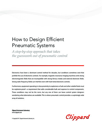
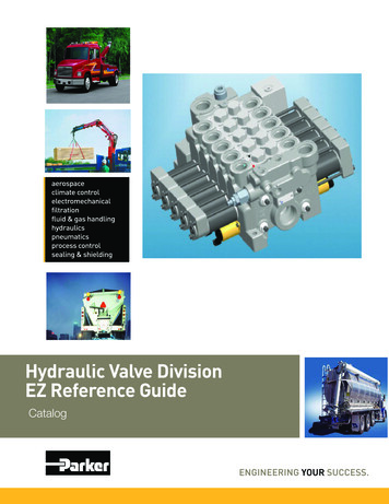
Service Application ManualSAM Chapter 620-83Section 7BPNEUMATIC CONTROLS – PREVENTIVE MAINTENANCEAND TROUBLESHOOTINGJohnson Controls, Inc.INTRODUCTIONA pneumatic control system is more sophisticated and complex than many electrical control systems. Toproperly maintain and service a pneumatic control, it is important for the service technician to be familiarwith all aspects of the system, from basics to the adjustment of the individual components .This chapter covers maintenance, components, and adjusting instructions for a typical pneumatic controlsystem.MAINTENANCEPreventive maintenance is required to ensure optimum system operation. Although the components of allcontrol systems are of the highest quality available and should give many years of excellent service, it isessential that the following routine preventive maintenance procedures be followed.INSTRUMENT AIR SYSTEMAIR COMPRESSORIntake Air FilterThe air filter cartridge should be cleaned or replaced every 30 to 90 days, depending on the cleanliness ofair entering the system. A greater frequency of cleaning and replacement may be required if an excessiveamount of dust and dirt is present. A compressor may pump oil if the air intake filter is dirty. An air filter isshown in Figure 1.Air FilterOIL FILTERThe coalescent in-line oil filter shown in Figure 2 has an integral gage, which indicates pressure dropacross the filter. A filter should be changed when the pressure drop across it is 20 psi, or output pressuredrops to 50 psig, whichever occurs first.1
Service Application ManualSAM Chapter 620-83Section 7BPNEUMATIC CONTROLS – PREVENTIVE MAINTENANCEAND TROUBLESHOOTINGJohnson Controls, Inc.Oil Filter and GageAn automatic drain in the bottom of the filter has a float valve that raises when entrapped liquids reach acertain level. Liquids are then blown out the bottom of the drain. The automatic drain should be cleaned,whenever the filter cartridge is replaced, with a household detergent or a specific solvent made for thispurpose. DO NOT use any solvents that may be harmful to polycarbonates.CAUTION:After cleaning or replacing a filter cartridge, air pressure should be returned gradually tothe system. A high surge of air pressure can destroy the cartridge.BELT ADJUSTMENTBelt tension should be checked every 30 days. The belt should deflect approximately 1/4" with normalhand pressure. If the deflection is greater than nominal, the motor should be moved accordingly to adjustthe tension. Be sure to keep the pulley sheaves aligned.OIL LEVELOil level must be checked at least once a week and changed every 90 days or 500 operating hours,whichever comes first. Contact the local manufacturer's branch for type of oil recommended.OIL PRESSUREOil pressure on 1-hp compressors and larger should be maintained in the 7 to 15 psig range. Check fordirty lines or faulty pump if pressure is abnormal. On compressors smaller than 1 hp, check oil level only.MOISTURE IN AIR TANKSMoisture must be drained from air tanks weekly. When the outside air is cold and dry, there will be verylittle moisture. When it is hot and humid, water will collect very rapidly. Do not try to outguess the weather;check regularly.2
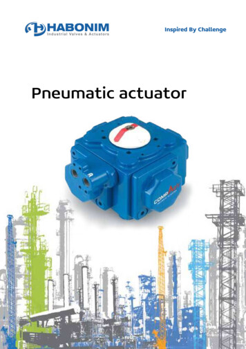
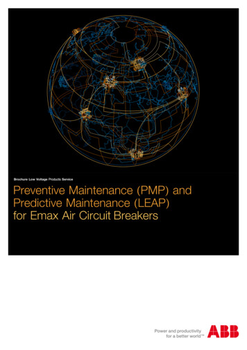
Service Application ManualSAM Chapter 620-83Section 7BPNEUMATIC CONTROLS – PREVENTIVE MAINTENANCEAND TROUBLESHOOTINGJohnson Controls, Inc.AIR DRYERSRefrigerated Air DryerThe refrigerated air dryer's automatic moisture removal trap must be checked regularly for float operation,and must be cleaned when a buildup of contaminants is noticed. The condenser is factory adjusted andsealed and should not be tampered with. The condenser coil should be cleaned with a vacuum cleanertwice a year.DESICCANT DRYERThe desiccant dryer shown in Figure 5 is a maintenance-free system as long as it receives oil-free air. Ifthe desiccant becomes oil contaminated to the point where it is not drying the air sufficiently, (when twothirds of the indicator turns pink) the desiccant chamber must be replaced.Desiccant DryerOUTPUT PRESSURECheck reducing valve output pressure daily. Refer to your control drawing for pressures recommended.Pressures should be maintained within ½ psig at the output of the pressure-reducing assembly(s). Thepressures in Figure 6 are standard.3
Service Application ManualSAM Chapter 620-83Section 7BPNEUMATIC CONTROLS – PREVENTIVE MAINTENANCEAND TROUBLESHOOTINGJohnson Controls, Inc.COMPRESSOR RUN TIMEThe size of the air compressor station has been selected to provide the necessary supply of compressedair for each control system. Periodically check the running time of the compressor under variousoperating conditions. Compressor running times above 60% are excessive. This can result from either airleaks in the system or inefficient air compressor operation. It is essential to find the cause of excessive airconsumption and correct the problem, since the increased running time can do damage to the aircompressor and also result in carry-over of moisture and oil to filters.AIR SUPPLY SYSTEM EXPANSIONBefore the control system is expanded to include additional pneumatic devices, the existing air supplysystem should be checked for sufficient capacity.PNEUMATIC ACTUATORSActuators can give years of trouble-free service. The actuator diaphragm is generally the only part thatever needs replacement. When a valve or damper actuator will not stroke, check for a sticking valve stemor for a binding damper linkage. Another possibility for an actuator not operating is an air leak in the airline between the controller and actuator. A simple method of determining if there is such an air leak is tolisten for air passing out of the controller at a high rate. (This condition will exist only if the controller isasking for a change in position.)4
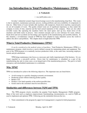
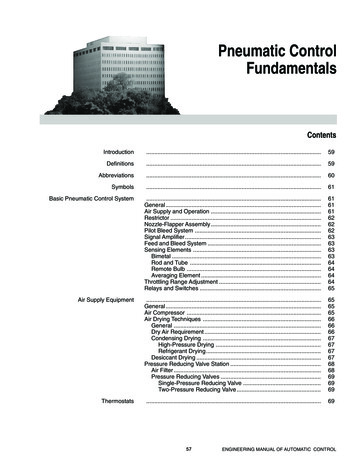
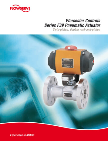
Service Application ManualSAM Chapter 620-83Section 7BPNEUMATIC CONTROLS – PREVENTIVE MAINTENANCEAND TROUBLESHOOTINGJohnson Controls, Inc.VALVESVisually check control valves periodically for leaks and sticking stems. Loss of a valve's ability to closetightly will suggest inspection of valve seats and discs for wear and contaminant buildup. Valvedisassembly and repair may require special tools. Contact your local manufacturer's representative forspecific recommendations and instructions.DAMPERSAutomatic control dampers must be checked periodically for tight closure, bent blades, and defectivelinkage. The damper shown in Figure 9 has oil-impregnated bearings that do not require lubrication,however, the linkage to the damper should be lubricated periodically to assure smooth operation.Frequency of lubrication will be determined by environment.DamperCONTROLLERSControllers of the type shown in Figure 10 are basically maintenance-free as long as they receive clean,dry air and are not abused. If the controller is contaminated with oil, the air supply system must bechecked for proper operation and oil should be eliminated from pneumatic lines before the controller isserviced or replaced. Contact your local manufacturer's rep if it is determined that oil is present in thecontrol air supply system.5
Service Application ManualSAM Chapter 620-83Section 7BPNEUMATIC CONTROLS – PREVENTIVE MAINTENANCEAND TROUBLESHOOTINGJohnson Controls, Inc.ControllersHVAC SYSTEMA control system cannot maintain proper conditions within a building unless the heating, ventilating, andair conditioning system is functioning as designed. It is therefore essential that the maintenancerecommended by the manufacturer of such equipment be performed. By the same token, a controlsystem cannot function properly if maintenance is not performed on it. In consideration of thisrequirement, a sample list of recommended maintenance tasks is offered below. It shows the major tasksconsidered essential for the continued efficient operation of a control system.MAINTENANCE CHECKLIST1. Air Compressora. drain moisture from tankb. check air pressure switch settingsc.check running timed. check oil pressuree. check oil level, fillf.change oilg. check pulley tightness, belt tensionh. check belt condition, change as requiredi.check operation of check valvej.change or clean suction filter6
Service Application ManualSAM Chapter 620-83Section 7BPNEUMATIC CONTROLS – PREVENTIVE MAINTENANCEAND TROUBLESHOOTINGJohnson Controls, Inc.2. Filter and Pressure Reductiona. check reducing valve pressure settingsb. operate safety valvec.check oil filter cartridge, cleand. check automatic trap operatione. clean trapsf.replace air filter element3. Refrigerated Air Dryera. check automatic traps, cleanb. clean condenser tubesc.clean cover grills4. HVAC and Fan System Controlsa. review cycle and sequence of operationb. check controllers for calibrationc.check operation of panel devicesd. clean control panele. check damper operationf.clean and lubricate damper linkageg. check operation sequence of damper actuatorsh. check operating range of pilotsi.check operation and sequence of valvesj.check operation of safety limits and minimum positioning devicesk.clean all instruments, covers, gages, etc.5. Room and Zone Controlsa. check operation and calibration of controllersb. check operation and sequence of unit valves and/or dampersc.clean all instruments, gages, etc.7
Service Application ManualSAM Chapter 620-83Section 7BPNEUMATIC CONTROLS – PREVENTIVE MAINTENANCEAND TROUBLESHOOTINGJohnson Controls, Inc.TRANSMITTERSSensitivityNever attempt to adjust the sensitivity. It is set at the factory and cannot be reset without the properequipment. If the red seal between the fixed sensitivity slider and the slider plate is broken, the warrantyis voided.TroubleshootingIf the transmission or indication system appears to be operating improperly, check the following beforechanging the starting point of the transmitter.1. Check for 20 psig supply air.2. Check for matching operating ranges of transmitter and indicators.3. Check indicator gages for accuracy at various pressures, such as 6, 9, and 12 psig, with aseparate input and gage.4. Check for transmission line problems. This can be done by placing an accurate indicating deviceand the transmitter measuring element side-by-side and comparing the reading of the indicatingdevice to the reading at the other end of the transmission line. If the reading at the end of thetransmission line is lower than that of the indicating device, check for a leak in the transmissionline, or a plugged or partially plugged restrictor (.007 in.).AdjustingIf the above checks have been made and the transmitter is still in error, proceed as follows:1. Take an accurate reading at the element.2. From the graphs (Figure 18), find the proper transmission pressure corresponding to themeasured reading. Be sure to use the vertical scale of Operating Ranges, which corresponds tothe range of the instrument being adjusted.8
Service Application ManualSAM Chapter 620-83Section 7BPNEUMATIC CONTROLS – PREVENTIVE MAINTENANCEAND TROUBLESHOOTINGJohnson Controls, Inc.3. Turn the starting point adjusting screw until the transmission pressure corresponds to the readingat the element.LOW LIMIT PROTECTIONThe importance of taking every precaution against freeze-up of equipment cannot be over-emphasized.Regardless of the automatic low-limit devices furnished, the following procedures should generally befollowed when there is any indication that the outside temperature will drop to the predetermined low-limitsetting.PUMPSAll hot water pumps and/or condensate or vacuum pumps should be operational.9
Service Application ManualSAM Chapter 620-83Section 7BPNEUMATIC CONTROLS – PREVENTIVE MAINTENANCEAND TROUBLESHOOTINGJohnson Controls, Inc.BOILERSBoilers and or converters should be allowed to cycle on a demand basis.SUPPLY AND EXHAUST FANSSupply fans should be allowed to operate on their normal occupied or unoccupied cycles. When on theunoccupied cycle, the outside air and exhaust dampers should be closed and the return air damper open.LOW-LIMIT THERMOSTAT OPERATIONThe low temperature limit protection device, located at the heating coil discharge, senses the lowesttemperature along any portion of its sensing element. When one foot or more of any portion of theelement senses a temperature as low as the thermostat set point, the instrument will open the circuit.Since the thermostat responds to a "spot" type condition, it is essential that stratification of air in themixing chamber entering the coil be eliminated, if proper operation is to be expected.Where repeated shut-downs occur as a result of this condition, a greater tendency exists for the operatingpersonnel to override or bypass the low-limit protection device in order to keep the unit running. This is adangerous practice and should be avoided. Further investigation as to the cause of shut-down shouldtake place to determine the cause of the problem, followed by appropriate remedial action.Low-limit protection devices should be checked prior to the arrival of cold weather. This can be done byturning the dial to a warmer setting until the low-limit protection device operates. The setting should equalthe temperature of the entering air or water. Do not forget to turn the device back to the original settingcalled for on the control diagram.SPECIAL PRECAUTIONSIn extremely cold weather, the following added precautions should be taken: Before air supply systemsare started, check steam traps and steam pressure and/or water temperature at the air supply system.After supply systems are started, check operation of the control system thermostats and observe forcorrect functioning with respect to the temperatures being sensed.OCCUPANT DISCOMFORTThe first evidence of trouble with the heating, ventilation, or cooling system is very often a complaint froman individual who is too hot, too cold, or is bothered with drafts. Go to the person complaining andpersonally check the complaint. Experience has shown that in the majority of cases, the problem behindthe complaint is not a malfunction of the control system. To assist in determining this, the various factors,other than automatic control, that can create comfort problems are listed:1. Zone Control.A person outside of the controlled zone may feel too hot or too cold. A zone control thermostatcan only sense the temperature at its particular location. Temperatures in all other areas of thezone are dependent on proper balance of the heating/cooling distribution system.2. Sun Load.Direct sunlight on the thermostat will cause overcooling of a zone while direct sunlight on theindividual will cause overheating.10
Service Application ManualSAM Chapter 620-83Section 7BPNEUMATIC CONTROLS – PREVENTIVE MAINTENANCEAND TROUBLESHOOTINGJohnson Controls, Inc.3. Covering of Grills.Frequently, occupants will cover part or all of a discharge grill causing improper heating orcooling. Whenever a grill is covered, the heating or cooling medium is not permitted to enter thespace to correct for variances from the setpoint.4. Occupant Location.If occupants are located adjacent to outside walls or windows, they may be subject to cold airleakage through the windows and/or radiant cooling from the walls.5. Insufficient Conditioned Air Supply.This can be caused by poor air distribution, dirty filters in the air conditioning unit, or lack ofproper return or exhaust air outlets.6. People and Equipment.Overheating will result if more people or equipment occupy an area than was intended in theoriginal design concept. This can occur when a meeting is held in an area not designed for thistype of function.7. Heating and Cooling System.A malfunction, or lack of capacity in extreme weather, of the primary or secondary mechanicalheating or cooling equipment may result in insufficient heating or cooling.8. Psychological Adjustment.Many complaints are purely psychological. Once a person understands the limitations of anHVAC system, he is more likely to accept prevailing conditions.9. Drafts.In systems using air as a means of heating and cooling, there must be movement of air. To manypeople, even a slight air motion is uncomfortable. This can be a problem when an unbalancedsystem causes excessive drafts. Minor problems can sometimes be solved by relocation of workstations; however, it is always best to have a balanced system, i.e., proper size, spacing, andfunctioning of air distribution equipment (fans, diffusers, grills, registers, etc.).10. Wide Fluctuation of Air Temperature.Wide fluctuation of air temperature in an area can be the result of varying load conditions orimproperly adjusted controls.11. Stuffiness.A stuffy or smoky atmosphere will normally result from improper ventilation, i.e., insufficient freshair supply, air too humid, over population, or inadequate exhaust.11
Service Application ManualSAM Chapter 620-83Section 7BPNEUMATIC CONTROLS – PREVENTIVE MAINTENANCEAND TROUBLESHOOTINGJohnson Controls, Inc.TROUBLESHOOTING: DIAGNOSING THE PROBLEMHVAC EQUIPMENTDepending on whether the area is too cold or too warm, and the time of year, check the heating,ventilating, and air conditioning equipment. This can include any or all of the following:1. Air Compressor and Pressure Reducing Station.2. Boiler.3. Refrigeration Compressor and/or Chilled Water System.4. Pumps.5. Secondary Heating and Air Conditioning Supply Systems.AUTOMATIC CONTROLSIf all the HVAC equipment checks out properly, the automatic control system should be checked asfollows: (This analysis is based on a complaint resulting from improper temperatures.)CONTROLLERCheck the set point of the controller for the correct setting. Check the output air pressure of theinstrument controlling the temperature in the complaint area. By examining the control diagram, theproper output pressure for the actual temperature conditions existing at the thermostat can bedetermined. If, for example, an overheated condition occurs, the thermostat output pressure should becalling for the source of heating to be shut "OFF" and the source of cooling to be "ON". If this is the case,it is not the thermostat causing the problem. If thermostat output pressure is not as described above, theproblem may be with the thermostat. Check the air supply pressure to thermostats for correct pressurelevel and for any air leaks. If the above are OK, move the dial of the thermostat slowly from one extremeto the other to see if the output pressure will vary over the entire range of supply pressure. If the pressuredoes vary, then it is probable that the thermostat is only out of adjustment and should be readjusted to thecorrect temperature setting.If there is no change in output pressure by moving the dial, there is a malfunction in the thermostat. If onlya partial change in pressure results, it can be the result of either:1. malfunction in the thermostat2. leak in the control pressure line3. leak in equipment being controlledCONTROLLED DEVICESCheck the automatic valve, damper actuator, etc., to see if they are in the proper position as called for bythe thermostat. If they are not, this may be the source of trouble.Copyright 1980, 2001, By Refrigeration Service Engineers Society.12
Johnson Controls, Inc. INTRODUCTION A pneumatic control system is more sophisticated and complex than many electrical control systems. To properly maintain and service a pneumatic control, it is important for the service technician to be familiar with all aspects of the system, from basics to the adjustment of the individual components .