Transcription
ITG Electronics, Inc.Mitigating EMI Problems&Filter SelectionByRafik StepanianEngineering Electronic Partnerships since 1963www.ITG-Electronics.com
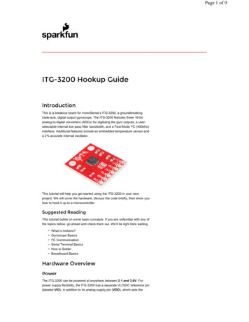
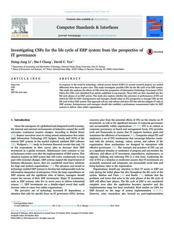
ITG Electronics, Inc.EMI Noise GeneratorsA change of state (On/Off ) in an Electronic component has the potential togenerate EMI. Typical examples are Electronic Switchers, Clocks, Electroniccontrols, Power Supplies, Inverters, Fluorescent lights, Motor Brushes, etc.”EMI noise could;Conduct through the power lines and it could be;Common Mode, between Line or Neutral to GroundDifferential Mode, between Line and NeutralRadiate through AirEngineering Electronic Partnerships since 1963www.ITG-Electronics.com
ITG Electronics, Inc.Curtesy of EMC consultant, FranceEngineering Electronic Partnerships since 1963www.ITG-Electronics.com
ITG Electronics, Inc.How to mitigate EMI?EMI is known as “Black Magic”. No one wants to deal with it because ithas no perceived market value, it is an economical burden which is ignoreduntil one starts reading the paragraphs in fine print which reads;“The system must meet theEMI requirements of ”Which means it is“TIME FOR 911 CALL”Most of the times the engineer is in a lab and the unit failed EMI testand the most common question is“Do you have a filter which passes MIL-STD-461 or ”Engineering Electronic Partnerships since 1963www.ITG-Electronics.com
ITG Electronics, Inc.MIL-STD’s and EN’s Provide: EMI limitsDetail test methodsTest proceduresTest apparatusWhat they don’t or can’t provide obviously is how much noise the DUT generatesEMI filters are application specific and they provide: “X” dB at certain frequencyOff the shelf (OTS) filters are designed to attenuate CM noise above 150KHz for commercialapplicationsThe OTS filters are not suitable for most military applications because the EMI test frequencystarts at 10KHzCM components have little effective below 100KHz, therefore DM components are necessary tosuppress the lower frequency noiseEngineering Electronic Partnerships since 1963www.ITG-Electronics.com
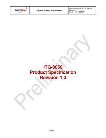
ITG Electronics, Inc.TYPICA EMI FILTERSEngineering Electronic Partnerships since 1963www.ITG-Electronics.com
ITG Electronics, IncPower Line Filters ComponentsCommon Mode CoilEngineering Electronic Partnerships since 1963Differential Mode Coilwww.ITG-Electronics.com
ITG Electronics, Inc“X”, “Y” or By-Pass CapacitorsEngineering Electronic Partnerships since 1963“F/T” Capacitorwww.ITG-Electronics.com
ITG Electronics, Inc.Following are the minimum information required tostart a filter design/selection Filter application Military, industrial or CommercialVoltage rating, DC or ACPower line frequency, 50/60/400HzCurrent ratingLeakage currentSingle or three phaseThree phase Delta or WYERequired attenuation (dB VS frequency)Or results from EMI test w/o a filter installedAvailable volumeMounting meansTermination (fast-on, screw, Mil connectors, etc.)Environmental requirementsEngineering Electronic Partnerships since 1963www.ITG-Electronics.com
ITG Electronics, Inc.Things to know when choosing an EMI filter1. In commercial world the conducted emissions measurement starts from 150KHz to30MHz, the radiated Emissions starts from 30MHz to 300KHz, and up.2. In military world the conducted emissions measurement starts from 10KHz to10MHz, the radiated Emissions starts from 10MHz to 1GHz and up.3. Whether in an EMI lab or in house performing EMI test if you are lucky the DUTwill pass, but if it fails save/print the results.4. Perform a Common Mode noise test save/print the results.5. Record the failed frequency starting from the lowest frequency and correspondingdB values above the limit line.Engineering Electronic Partnerships since 1963www.ITG-Electronics.com
ITG Electronics, Inc.Continued;6. If the failed frequencies are at 150KHz and up you may start with a simple LC or PIconfiguration filter.7. Use the recorded data dB Vs frequency and compare with data sheets provided by filtermanufacturer and choose a filter and repeat EMI test.8. If EMI test results are better but not quite there yet, what you need to know is each filtercomponent in theory provide: 6dB additional attenuation when its value is doubled6dB less attenuation when its value is cut in half6dB additional attenuation per octave (every time the frequency is doubled)20dB additional attenuation per decade (every time the frequency is multiplied by 10)Additional component increases the filters attenuation by 20 dBNote: you may use the above during system simulation.Engineering Electronic Partnerships since 1963www.ITG-Electronics.com
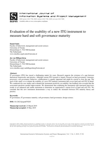
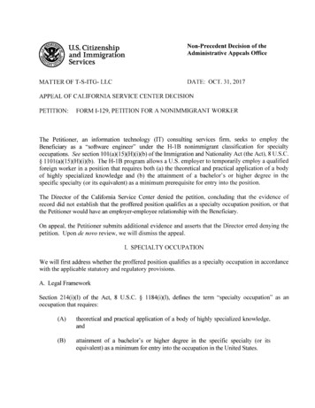
ITG Electronics, Inc.Typical filter circuit and it’s attenuation response in ideal situation6dB attenuation per OctaveEngineering Electronic Partnerships since 196320dB attenuation per Decadewww.ITG-Electronics.com
ITG Electronics, Inc.2L 6dB more attenuationEngineering Electronic Partnerships since 19631/2L, 6dB less attenuationwww.ITG-Electronics.com
ITG Electronics, Inc.2xL & 2xC, 12dB more attenuationEngineering Electronic Partnerships since 19631/2xL 1/2xC, 6dB less attenuationwww.ITG-Electronics.com
ITG Electronics, Inc.Case StudyEMI Filter Design based on EMI test results480VAC 60Hz 200A InverterEngineering Electronic Partnerships since 1963www.ITG-Electronics.com
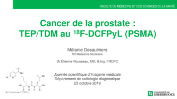
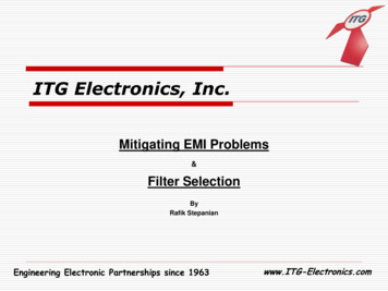
ITG Electronics, Inc.MIL STD-461, CE102 test results without EMI filterEngineering Electronic Partnerships since 1963www.ITG-Electronics.com
ITG Electronics, Inc.Initial open frame prototype500uH10uF500uH10uF0.01uFPhase APhase APhase BPhase BINPUTOUTPUTPhase CPhase CCase GNDEngineering Electronic Partnerships since 1963www.ITG-Electronics.com
ITG Electronics, Inc.MIL STD-461, CE102 test results with prototype filterEngineering Electronic Partnerships since 1963www.ITG-Electronics.com
ITG Electronics, Inc.750uH20uF750uH20uF0.01uFPhase APhase APhase BPhase BINPUTOUTPUTPhase CPhase CCase GNDEngineering Electronic Partnerships since 1963www.ITG-Electronics.com
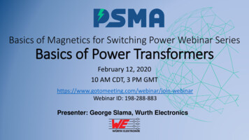
ITG Electronics, Inc.MIL STD-461, CE102 test results with final EMI filter installationEngineering Electronic Partnerships since 1963www.ITG-Electronics.com
ITG Electronics, Inc.Does and don’ts during electronic designWhere possible: Use multilayer PCB design with ground planes in between layersShort traces where possible to reduce antenna affectPlace noisy components in one areaAvoid sharp (90 degree) trace bends, round off the trace edges and cornersUse wire harnessSeparate noisy cables from power line cablesIf using shielded cables connect shield to ground at least one endDo not daisy chain ground wires, have one common ground and ground wires as short aspossibleUse shielding material around the covers and doorsMake sure areas where shielded materials are used are not paintedRead fine prints on your spec and if there is an EMI requirements make sure to leavespace for an EMI filter.Perform EMI test during prototype design phaseEngineering Electronic Partnerships since 1963www.ITG-Electronics.com
ITG Electronics, Inc. Military and Commercial EMI test are performed in a 50 ohms system using LISN’s (Line ImpedanceStabilization Network) Conducted emissions testing is performed on power cables entering the equipment. The reason is toprevent EMI noise generated by electronics switches is contained in the chassis and will not transmitthrough the power cables and adversely effect the performance of other equipment connected to thesame power line Military and commercial EMI spec provide limits and test procedures not solution guide lines If emissions measured exceeds the allowable limits EMI filters are required EMI Filters are bi-directional and they mitigate conducted emissions. They are most effective at lowerfrequencies and their harmonics at higher frequency spectrum To enhance the performance of the EMI filters they should be installed at the power line entering theequipment, preferably input terminals protruding out of the enclosure isolated from filter outputterminals The isolation will prevent cross talk between input (dirty) and output (clean) terminals and willpositively effects the radiated emissions test resultsEngineering Electronic Partnerships since 1963www.ITG-Electronics.com
ITG Electronics, Inc.1. While in the EMI lab doing EMI test if the product fails, the very first thing to do is printthe results.2. Perform a Common Mode noise test (most labs know how to perform this test) and printthe results.3. Write down the failed frequency and corresponding dB margin above the limit line.4. In the commercial world the conducted emissions measurement starts from 150KHz to30MHz, the radiated Emissions starts from 30MHz to 300KHz, or 1GHz depending on theproduct under test.5. In the military world the conducted emissions measurement starts from 10KHz to 10MHz,the radiated Emissions starts from 10MHz to 1GHz and up depending on the productunder test.6. If the failed frequencies are at 150KHz and up you may start with a simple LC filter. Hereis what you need to know, every element initially provides 6dB attenuation, an LC filterwill provide total 12db attenuation above the cut off frequency. If the L or C or bothcomponent values are doubled, each will provide 6dB additional attenuation per element.7. Each filter component element provides:a) 6dB attenuation per octave (every time the frequency is doubled)b) 20dB attenuation per decade (every time the frequency is multiplied by 10)c) 6dB attenuation when the value of a component is doubledd) 6dB less attenuation when the value of a component is cut in halfe) Additional component adds 20dB attenuationEngineering Electronic Partnerships since 1963www.ITG-Electronics.com
ITG Electronics, Inc.ConclusionThe EMI solution once designed will work for years, as long as the filtercomponents are properly selected for voltage fluctuation and maximum operatingcurrent and environmental requirements. EMI solutions do not need regularlyscheduled maintenance. What is important is the manufacturing consistency ofthe system the EMI solutions are designed for. Any changes no matter howinsignificant the they are it is recommended to repeat EMI test to prevent futurecostly field recalls because of EMI failure. As you can see EMI solution is not“Black Magic” it is based on a technology from past, which is reliable and mostimportantly it still worksEngineering Electronic Partnerships since 1963www.ITG-Electronics.com
ITG Electronics, Inc.Cost of Incorporating EMI solutionEngineering Electronic Partnerships since 1963www.ITG-Electronics.com
ITG Electronics, Inc.Worldwide Support Team: We work closely with customers on new design activity as well assupplies and demand management. Inventory in LA, Elmsford NY, Hong Kong and Shanghai, China tosupport regional demand.Our global help hotline:USA: 1-914-347-2474 (NY Office)USA: 1-914-806-8063 (PA Office)Japan: 81-568-85-2830Taipei: 886-2-2698-8669Kaohsiung: 886-7-350-2275Hong Kong: 852-9688-9767ShenZhen: 86-755-8418-6263Shanghai: 86-21-5424-5141E-mail: sales@ITG-Electronics.comEngineering Electronic Partnerships since 1963www.ITG-Electronics.com
Engineering Electronic Partnerships since 1963 www.ITG-Electronics.com ITG Electronics, Inc. 6. If the failed frequencies are at 150KHz and up you may start with a simple LC or PI configuration filter. 7. Use the recorded data dB Vs frequency and compare with data sheets provided by filter manufacturer and choose a filter and repeat EMI test. 8.