Transcription
ITG-3050 Product SpecificationDocument Number: PS-ITG-3050-00Revision: 1.3Release Date: 08/25/2011ITG-3050Product SpecificationRevision 1.31 of 42
ITG-3050 Product SpecificationDocument Number: PS-ITG-3050-00Revision: 1.3Release Date: 08/25/2011CONTENTS1DOCUMENT INFORMATION .41.11.21.31.41.52FEATURES .82.12.22.32.42.52.632I C SERIAL INTERFACE .24SERIAL INTERFACE CONSIDERATIONS .287.17.28BLOCK DIAGRAM .18OVERVIEW .18THREE-AXIS MEMS GYROSCOPE WITH 16-BIT ADCS AND SIGNAL CONDITIONING .182PRIMARY I C SERIAL COMMUNICATIONS INTERFACE.192RDSECONDARY I C SERIAL INTERFACE (FOR 3 -PARTY ACCELEROMETERS) .19RD3 PARTY ACCELEROMETER CIRCUIT CONFIGURATIONS .22INTERNAL CLOCK GENERATION .22CLOCK OUTPUT.23SENSOR DATA REGISTERS .23FIFO .23INTERRUPTS.23DIGITAL-OUTPUT TEMPERATURE SENSOR .23BIAS AND LDO .23CHARGE PUMP .23DIGITAL INTERFACE.246.17PIN OUT AND SIGNAL DESCRIPTION.15TYPICAL OPERATING CIRCUIT .16BILL OF MATERIALS FOR EXTERNAL COMPONENTS.16RECOMMENDED POWER-ON PROCEDURE .17FUNCTIONAL OVERVIEW 6SENSOR SPECIFICATIONS .9ELECTRICAL SPECIFICATIONS.10ELECTRICAL SPECIFICATIONS, CONTINUED .11ELECTRICAL SPECIFICATIONS, CONTINUED .122I C TIMING CHARACTERIZATION .13ABSOLUTE MAXIMUM RATINGS .14APPLICATIONS INFORMATION .154.14.24.34.45SENSORS .8DIGITAL OUTPUT .8DATA PROCESSING .8CLOCKING .8POWER .8PACKAGE .8ELECTRICAL CHARACTERISTICS .93.13.23.33.43.53.64REVISION HISTORY .4PURPOSE AND SCOPE .5PRODUCT OVERVIEW.5SOFTWARE SOLUTIONS .5APPLICATIONS .7ITG-3050 SUPPORTED INTERFACES .28LOGIC LEVELS .28ASSEMBLY .312 of 42
ITG-3050 Product Specification8.18.28.38.48.58.68.78.89Document Number: PS-ITG-3050-00Revision: 1.3Release Date: 08/25/2011ORIENTATION OF AXES .31PACKAGE DIMENSIONS: .32PCB DESIGN GUIDELINES:.33ASSEMBLY PRECAUTIONS .34PACKAGE MARKING SPECIFICATION .37TAPE & REEL SPECIFICATION .38LABEL .39PACKAGING.40RELIABILITY .419.19.210QUALIFICATION TEST POLICY .41QUALIFICATION TEST PLAN .41ENVIRONMENTAL COMPLIANCE .423 of 42
ITG-3050 Product Specification1Document Number: PS-ITG-3050-00Revision: 1.3Release Date: 08/25/2011Document Information1.1Revision 1.105/25/20111.208/25/20111.3DescriptionInitial ReleaseSec. 1.4Provided additional information to software solution sectionSec. 3.2Added CLKOUT Digital Output specificationSec. 8.4.3 Clarified Trace Routing PrecautionsSec. 4.1Sec. 4.4Specified CLKIN and FSYNC to be connected to GND if unused.Modified TVDDR value for consistency with ElectricalCharacteristicsSec. 1.4Clarified upgrade path to InvenSense’s MPU and IMU productfamilies and integration with software solutions.rdAdded section describing and providing diagrams for the 3 partyAccelerometer circuit configurationsSec. 5.64 of 42
ITG-3050 Product Specification1.2Document Number: PS-ITG-3050-00Revision: 1.3Release Date: 08/25/2011Purpose and ScopeThis document is a product specification, providing a description, specifications, and design relatedinformation for the ITG-3050 .1.3Product OverviewThe ITG-3050 is a single-chip, digital output, 3-Axis MEMS gyro IC which features a 512-byte FIFO and a2rdsecondary I C sensor bus that interfaces to 3 party digital accelerometers. The combination of FIFO anddedicated sensor bus allows the ITG-3050 to directly acquire data from an off-chip accelerometer withoutintervention from an external processor. This both lowers the traffic on the primary (application processor)bus interface and saves power by allowing the system processor to burst read sensor data from the ITG3050’s FIFO and then go into a low-power sleep mode while the device collects more data.The ITG-3050 features a 3-axis digital gyro with programmable full-scale ranges of 250, 500, 1000, and 2000 degrees/sec (dps or /sec), which is useful for precision tracking of both fast and slow motions. Ratenoise performance sets the industry standard at 0.01 dps/ Hz, providing the highest-quality user experiencein pointing, gaming, user interface, and other motion-based applications. Factory-calibrated initial sensitivityreduces production-line calibration requirements.Other industry-leading features include on-chip 16-bit ADCs, programmable digital filters, a precision clockwith 1% drift from -40 C to 85 C, an embedded temperature sensor, programmable interrupts, and a low25.9mA supply current. The ITG-3050 comes with an I C serial interface, a VDD operating range of 2.1 to3.6V, and a VLOGIC interface voltage from 1.71V to 3.6V.By leveraging its patented and volume-proven Nasiri-Fabrication platform, which integrates MEMS waferswith companion CMOS electronics through wafer-level bonding, InvenSense has driven the ITG-3050package size down to a revolutionary footprint of 4x4x0.9mm (QFN), while providing the highestperformance, lowest noise, and the lowest cost semiconductor packaging to address a wide range ofhandheld consumer electronic devices. The device provides the highest robustness by supporting 10,000gshock in operation. The highest cross-axis isolation is achieved by design from its single silicon integration.1.4Software SolutionsThis section describes the MotionApps software solutions included with the InvenSense MPU (MotionProcessing Unit ) and IMU (Inertial Measurement Unit) product families.Please note that the products within the IDG, IXZ, and ITG gyroscope families do not include thesesoftware solutions. The MPU and IMU product families are pin compatible with the digital IDG, IXZ, andITG families, and provide a simple swap and replace upgrade path to integrate InvenSense’s softwaresolutions.The MotionApps Platform is a complete software solution that in combination with the InvenSense IMU andMPU MotionProcessor families delivers robust, well-calibrated 6-axis and/or 9-axis sensor fusion datausing its field proven and proprietary MotionFusion engine. Solution packages are available forsmartphones and tablets as well as for embedded microcontroller-based devices.The MotionApps Platform provides a turn-key solution for developers and accelerates time-to-market. Itconsists of complex 6/9-axis sensor fusion algorithms, robust multi-sensor calibration, a proven softwarearchitecture for Android and other leading operating systems, and a flexible power management scheme.The MotionApps Platform is integrated within the middleware of the target OS (the sensor framework), andalso provides a kernel device driver to interface with the physical device. This directly benefits applicationdevelopers by providing a cohesive set of APIs and a well-defined sensor data path in the user-space.5 of 42
Document Number: PS-ITG-3050-00Revision: 1.3Release Date: 08/25/2011ITG-3050 Product SpecificationThe table below describes the MotionApps software solutions included with the InvenSense MPU and IMUproduct families.InvenSense MotionProcessor Devices and Included MotionApps SoftwareIncluded otionAppsLiteMPU-3050MPU-6050Part NumberProcessor ocontrollerN/ASmartphones,tabletsTV remotes,health/fitness,toys, otherembeddedSmartphones,tabletsTV remotes,health/fitness,toys, otherembeddedN/A6-Axis MotionFusionYesYesNo 2% Application Processorload using on-chip DigitalMotion Processor (DMP).9-Axis MotionFusionYesNoNoReduces processingrequirements for embeddedapplicationsGyro Bias CalibrationYesYesNoNo-Motion calibration andtemperature calibration3rd Party Compass CalAPIYesNoNoIntegrates 3rd party compasslibrariesGyro-Assisted CompassCalibration (Fast Heading)YesNoNoQuick compass calibrationusing gyroscopeMagnetic AnomalyRejection(Improved Heading)YesNoNoUses gyro heading datawhen magnetic anomaly isdetectedThe table below lists recommended documentation for the MotionApps software solutions.Software DocumentationPlatformMotionApps and MotionApps LiteEmbeddedMotionAppsEmbedded MotionApps LiteSoftwareDocumentation Installation Guide for Linux and AndroidMotionApps Platform, v1.9 or later Embedded MotionApps PlatformUser Guide, v3.0 or later MPL Functional Specifications Embedded MPL FunctionalSpecificationsandFor more information about the InvenSense MotionApps Platform, please visit the Developer’s Corner orconsult your local InvenSense Sales Representative.6 of 42
ITG-3050 Product Specification1.5Applications Motion-enabled game controllersHandheld gamingHandset User InterfaceMotion-based Digital TV and Set Top Box remote controlsLocation based services, points of interest, and dead reckoningImproved camera image quality through image stabilizationHealth and sports monitoring7 of 42Document Number: PS-ITG-3050-00Revision: 1.3Release Date: 08/25/2011
ITG-3050 Product Specification2Document Number: PS-ITG-3050-00Revision: 1.3Release Date: 08/25/2011FeaturesThe ITG-3050 triple-axis MEMS gyroscope includes a wide range of features:2.1Sensors 2.2Digital Output 2.3 On-chip timing generator clock frequency 1% drift over full temperature rangeOptional external clock inputs of 32.768kHz or 19.2MHz1MHz clock output to synchronize with digital 3-axis accelerometerPower 2.6rdWhen used together with a 3 -party digital 3-axis accelerometer, the ITG-3050 collects theaccelerometer data via a dedicated sensor interface, while synchronizing data sampling at a userdefined rate. The total data set obtained by the ITG-3050 includes 3-axis gyroscope data, 3-axisaccelerometer data, temperature data, and the one bit external sync signal connected to therdFSYNC pin. The ITG-3050 also downloads the results calculated by the digital 3-axis 3 partyaccelerometer internal registers.FIFO buffers complete data set, reducing timing requirements on the system processor andsaving power by letting the processor burst read the FIFO data, and then go into a low-powersleep mode while the ITG-3050 collects more data.Programmable interruptProgrammable low-pass filtersClocking 2.52Fast Mode (400kHz) I C serial interface16-bit ADCs for digitizing sensor outputsAngular rate sensors (gyros) with user-programmable full-scale-range of 250 /sec, 500 /sec, 1000 /sec, or 2000 /sec.Data Processing 2.4X-, Y-, Z-Axis angular rate sensors (gyros) on one integrated circuitDigital-output temperature sensorExternal sync signal connected to the FSYNC pin supports image, video and GPSsynchronization2rdSecondary I C interface directly connects to a digital 3-axis 3 -party accelerometerFactory calibrated scale factorHigh cross-axis isolation via proprietary MEMS design10,000g shock tolerantVDD supply voltage range of 2.1V to 3.6V2Flexible VLOGIC reference voltage allows for multiple I C interface voltage levelsPower consumption with all three axis active: 5.9mASleep mode: 5μAEach axis can be individually powered downPackage 4x4x0.9mm QFN plastic packageMEMS structure hermetically sealed and bonded at wafer levelRoHS and Green compliant8 of 42
Document Number: PS-ITG-3050-00Revision: 1.3Release Date: 08/25/2011ITG-3050 Product Specification3Electrical Characteristics3.1Sensor SpecificationsTypical Operating Circuit of Section 4.2, VDD 2.5V, VLOGIC 2.5V, TA 25 C.ParameterGYRO SENSITIVITYFull-Scale RangeGyro ADC Word LengthSensitivity Scale FactorSensitivity Scale Factor ToleranceSensitivity Scale Factor Variation OverTemperatureNonlinearityCross-Axis SensitivityGYRO ZERO-RATE OUTPUT (ZRO)Initial ZRO ToleranceZRO Variation Over TemperaturePower-Supply Sensitivity (1-10Hz)Power-Supply Sensitivity (10 - 250Hz)Power-Supply Sensitivity (250Hz 100kHz)Linear Acceleration SensitivityGYRO NOISE PERFORMANCETotal RMS NoiseLow-frequency RMS noiseRate Noise Spectral DensityConditionsMinFS SEL 0FS SEL 1FS SEL 2FS SEL 3FS SEL 0FS SEL 1FS SEL 2FS SEL 325 C-40 C to 85 C-6Best fit straight line; 25 C25 C-40 C to 85 CSine wave, 100mVpp; VDD 2.2VSine wave, 100mVpp; VDD 2.2VSine wave, 100mVpp; VDD 2.2VStaticFS SEL 0DLPFCFG 2 (100Hz)Bandwidth 1Hz to10HzAt 10HzGYRO MECHANICAL FREQUENCIESX-AxisY-AxisZ-Axis302724GYRO START-UP TIMEZRO SettlingDLPFCFG 0to 1º/s of FinalTEMPERATURE SENSORRangeSensitivityRoom-Temperature OffsetLinearityTEMPERATURE RANGESpecified Temperature RangeUntrimmed35 CBest fit straight line (-30 C to 85 C)-40Notes:1.2.3.4.5.6.7.TypicalUnitNotesº/s%%4, 74, 74, 74, 731333180.22%%66 20 0.10.0330.01º/s-r m sº/s-r m sº/s/ Hz113kHzkHzkHz11150ms5-30 to 85280-13200 1ºCLSB/ºCLSB C2212ºC2 250 500 1000 20001613165.532.816.4 2 2333027MaxbitsLSB/(º/s) 636333085Tested in productionBased on characterization of 30 parts over temperature on evaluation board or in socketBased on design, through modeling, and simulation across PVTTypical. Randomly selected part measured at room temperature on evaluation board or in socketBased on characterization of 5 parts over temperatureTested on 20 parts at room temperature16Part is characterized to Full-Scale Range. Maximum ADC output is [2 / (Sensitivity x 2)]16Example: For Sensitivity of 131 LSB/(º/s), [2 / (131 x 2)] 250 º/s.8. Based on characterization of 48 parts on evaluation board or in socket9 of 42
ITG-3050 Product Specification3.2Document Number: PS-ITG-3050-00Revision: 1.3Release Date: 08/25/2011Electrical SpecificationsTypical Operating Circuit of Section 4.2, VDD 2.5V, VLOGIC 2.5V, TA 25 C.ParametersConditionsMinVDD POWER SUPPLYOperating Voltage RangePower-Supply Ramp RateMonotonic ramp. Ramprate is 10% to 90% of thefinal value (see Figure inSection 4.4)MaxUnitsNotes2.13.6V205ms2mAµA14VDDV3, 51ms3, 5µA4ms4Normal Operating CurrentSleep Mode CurrentTypical5.95VLOGIC REFERENCE VOLTAGE(must be regulated)Voltage RangePower-Supply Ramp RateNormal Operating CurrentVLOGIC must be VDD atall timesMonotonic ramp. Ramprate is 10% to 90% of thefinal value(see Figure in Section 4.4)Does not include pull upresistor current draw asthat is system dependent1.71100START-UP TIME FOR REGISTERREAD/WRITEI2C ADDRESS20AD0 0AD0 111010001101001DIGITAL INPUTS (SDI, SCLK,FSYNC, AD0, /CS, CLKIN)VIH, High Level Input VoltageVIL, Low Level Input VoltageCI, Input CapacitanceDIGITAL OUTPUT (INT)VOH, High Level Output VoltageVOL1, LOW-Level Output VoltageVOL.INT1, INT Low-Level Output Voltage10.7*VLOGIC0.3*VLOGIC 5Output Leakage CurrenttINT, INT Pulse WidthRLOAD 1MΩRLOAD 1MΩOPEN 1, 0.3mA sinkcurrentOPEN 1LATCH INT EN 0DIGITAL OUPUT (CLKOUT)VOH, High Level Output VoltageVOL1, Low Level Output VoltageRLOAD 1MΩRLOAD 00500.9*VDD0.1*VDDVVpF446VVV222nAµs33VV22Tested in productionBased on characterization of 30 parts over temperature on evaluation board or in socketTypical. Randomly selected part measured at room temperature on evaluation board or in socketBased on characterization of 5 parts over temperatureRefer to Section 4.4 for the recommended power-on procedureGuaranteed by design10 of 42
Document Number: PS-ITG-3050-00Revision: 1.3Release Date: 08/25/2011ITG-3050 Product Specification3.3Electrical Specifications, continuedTypical Operating Circuit of Section 4.2, VDD 2.5V, VLOGIC 2.5V, TA 25 C.ParametersConditionsPrimary I2C I/O (SCL, SDA)VIL, LOW Level Input VoltageVIH, HIGH-Level Input VoltageVhys, HysteresisVOL1, LOW-Level Output VoltageIOL, LOW-Level Output Current3mA sink currentVOL 0.4VVOL 0.6VOutput Leakage Currenttof, Output Fall Time from VIHmax to VILmaxCI, Capacitance for Each I/O pinSecondary I2C I/O (AUX CL,AUX DA)VIL, LOW-Level Input VoltageCb bus capacitance inpfVhys, HysteresisVOL3, LOW-Level Output VoltageIOL, LOW-Level Output CurrentVLOGIC 2V; 1mA sinkcurrentVLOGIC 2V; 1mA sinkcurrentVOL 0.4VVOL 0.6VOutput Leakage Currenttof, Output Fall Time from VIHmax to VILmaxCI, Capacitance for Each I/O pinSecondary I2C I/O (AUX CL,AUX DA)VIL, LOW-Level Input VoltageVIH, HIGH-Level Input VoltageVhys, HysteresisVOL1, LOW-Level Output VoltageIOL, LOW-Level Output CurrentOutput Leakage Currenttof, Output Fall Time from VIHmax to VILmaxCI, Capacitance for Each I/O pinUnitsNotes-0.5V to 0.3*VLOGIC0.7*VLOGIC to VLOGIC 0.5V0.1*VLOGIC0 to 0.435100VV11VVmAmAnA1111220 0.1Cb to 250ns1 10pF3-0.5V to 0.3*VLOGIC0.7*VLOGIC toVLOGIC 0.5V0.1*VLOGICV1V1V10 to 0.4V10 to 0.2*VLOGICV111100mAmAnA11220 0.1Cb to 250ns1 10pF3-0.5 to 0.3*VDD0.7*VDD to VDD 0.5V0.1*VDD0 to 0.411100VVVVmAmAnAnspF111111213AUX VDDIO 0VIH, HIGH-Level Input VoltageVOL1, LOW-Level Output VoltageTypicalCb bus capacitance inpFAUX VDDIO 11mA sink currentVOL 0.4VVOL 0.6VCb bus cap. in pF20 0.1Cb to 250 10Notes:1. Based on characterization of 5 parts over temperature.2. Typical. Randomly selected part measured at room temperature on evaluation board or in socket3. Guaranteed by design11 of 42
Document Number: PS-ITG-3050-00Revision: 1.3Release Date: 08/25/2011ITG-3050 Product Specification3.4Electrical Specifications, continuedTypical Operating Circuit of Section 4.2, VDD 2.5V, VLOGIC 2.5V, TA 25 C.ParametersConditionsINTERNAL CLOCK SOURCECLK SEL 0,1,2,3Sample Rate, FastDLPFCFG 0SAMPLERATEDIV 0Sample Rate, SlowDLPFCFG 1,2,3,4,5, or 6SAMPLERATEDIV 0Reference Clock OutputClock Frequency Initial ToleranceFrequency Variation over TemperaturePLL Settling TimeEXTERNAL 32.768kHz CLOCKExternal Clock FrequencyExternal Clock JitterCLKOUTEN 1CLK SEL 0, 25 CCLK SEL 1,2,3; 25 CCLK SEL 0CLK SEL 1,2,3CLK SEL 1,2,3MinTypicalMaxUnitsNotes8kHz31kHz3-15 to 10 /-11MHz%%%%ms31122432.7681 to 2kHzµs441.024-5-1 5 1CLK SEL 4Cycle-to-cycle r m sSample Rate, FastDLPFCFG 0SAMPLERATEDIV 08.192kHz4Sample Rate, SlowDLPFCFG 1,2,3,4,5, or 6SAMPLERATEDIV 01.024kHz41.04861MHzms4419.2MHz4Reference Clock OutputPLL Settling TimeCLKOUTEN 1EXTERNAL 19.2MHz CLOCKExternal Clock FrequencyCLK SEL 5Sample Rate, FastDLPFCFG 0SAMPLERATEDIV 08kHz4Sample Rate, SlowDLPFCFG 1,2,3,4,5, or 6SAMPLERATEDIV 01kHz41.0241MHzms44Reference Clock OutputPLL Settling TimeNotes:1.2.3.4.CLKOUTEN 1Tested in productionBased on characterization of 30 parts over temperature on evaluation board or in socketTypical. Randomly selected part measured at room temperature on evaluation board or in socketBased on design, through modeling, and simulation across PVT12 of 42
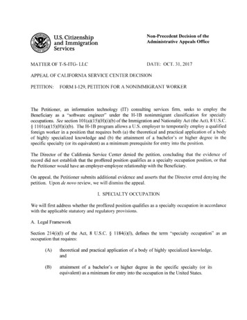
Document Number: PS-ITG-3050-00Revision: 1.3Release Date: 08/25/2011ITG-3050 Product Specification3.52I C Timing CharacterizationTypical Operating Circuit of Section 4.2, VDD 2.5V, VLOGIC 1.8V 5%, 2.5V 5%, 3.0V 5%, or 3.3V 5%,TA 25 Hzµs112I C TIMINGfSCL, SCL Clock FrequencytHD.STA, (Repeated) START ConditionHold TimeI C FAST-MODE00.6tLOW, SCL Low PeriodtHIGH, SCL High Period1.30.6µsµs11tSU.STA, Repeated START ConditionSetup Time0.6µs1tHD.DAT, SDA Data Hold TimetSU.DAT, SDA Data Setup s1tr, SDA and SCL Rise TimeCb bus cap. from 10 to400pFCb bus cap. from 10 to400pFtf, SDA and SCL Fall TimetSU.STO, STOP Condition Setup TimetBUF, Bus Free Time Between STOP andSTART ConditionCb, Capacitive Load for each Bus LinetVD.DAT, Data Valid Time20 0.1Cb20 0.1Cb0.61.3 400tVD.ACK, Data Valid Acknowledge TimeNotes:1. Based on characterization of 5 parts over temperature on evaluation board or in socket2. S Start Condition, P Stop Condition, Sr Repeated Start Condition3. Guaranteed by design2I C Bus Timing Diagram13 of 42
ITG-3050 Product Specification3.6Document Number: PS-ITG-3050-00Revision: 1.3Release Date: 08/25/2011Absolute Maximum RatingsStress above those listed as “Absolute Maximum Ratings” may cause permanent damage to the device.These are stress ratings only and functional operation of the device at these conditions is not implied.Exposure to the absolute maximum ratings conditions for extended periods may affect device reliability.Absolute Maximum RatingsParameterRatingSupply Voltage, VDD-0.5V to 6VVLOGIC Input Voltage Level-0.5V to VDD 0.5VREGOUT-0.5V to 2VInput Voltage Level (CLKIN, AUX DA, AD0,FSYNC, INT, SCL, SDA)CPOUT (2.1V VDD 3.6V )-0.5V to VDD 0.5V-0.5V to 30VAcceleration (Any Axis, unpowered)Operating Temperature Range10,000g for 0.3ms-40 C to 105 CStorage Temperature Range-40 C to 125 CElectrostatic Discharge (ESD) Protection1.5kV (HBM); 200V (MM)JEDEC Class II (2),125 CLevel B, 60mALatch-up14 of 42
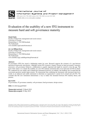
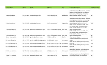
Document Number: PS-ITG-3050-00Revision: 1.3Release Date: 08/25/2011ITG-3050 Product Specification44.1Applications InformationPin Out and Signal DescriptionPin NumberPin NamePin Description1CLKIN6AUX DAInterface to a 3rd party accelerometer, SDA pin. Logic levels are set to beeither VDD or VLOGIC. See Section 6 for more details.7AUX CLInterface to a 3rd party accelerometer, SCL pin. Logic levels are set to beeither VDD or VLOGIC. See Section 6 for more details.8VLOGICDigital I/O supply voltage. VLOGIC must be VDD at all times.9AD010REGOUT11FSYNC12INTInterrupt digital output (totem pole or open-drain)13VDDPower supply voltage and Digital I/O supply voltage18GNDPower supply ground19RESVReserved. Do not connect.20CPOUT21RESV22CLKOUT23SCLI2C serial clock24SDAI2C serial data2, 3, 4, 5, 14,15, 16, 17NCNot internally connected. May be used for PCB trace routing.External reference clock input. Connect to GND if not used.I2C Slave Address LSBRegulator filter capacitor connectionFrame synchronization digital input. Connect to GND if not used.Charge pump capacitor connectionReserved. Do not connect.1MHz clock output for 3rd-party accelerometer synchronizationRESVCPOUTRESVSCLCLKOUTSDA24 23 22 21 20 19CLKIN118 GNDNC217 NCNC316 NCNC4NC5AUX DA6ITG-3050 ZITG- 3015 NC5014 NC13 VDD910 11 12 Y XAUX CLVLOGICAD0REGOUTINT8FSYNC7Orientation of Axes of Sensitivityand Polarity of RotationQFN Package (Top View)24-pin, 4mm x 4mm x 0.9mm15 of 42
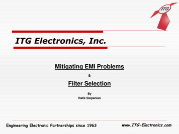
Document Number: PS-ITG-3050-00Revision: 1.3Release Date: 08/25/2011ITG-3050 Product Specification4.2Typical Operating 17GND316ITG-3050415VDD5146AUX DA13789101112C20.1µFAUX CLGNDC10.1µFVLOGICGNDINTFSYNCAD0C410nFGNDTypical Operating Circuit4.3Bill of Materials for External ator Filter CapacitorC1Ceramic, X7R, 0.1µF 10%, 2V1VDD Bypass CapacitorC2Ceramic, X7R, 0.1µF 10%, 4V1Charge Pump CapacitorC3Ceramic, X7R, 2.2nF 10%, 50V1VLOGIC Bypass CapacitorC4Ceramic, X7R, 10nF 10%, 4V116 of 42
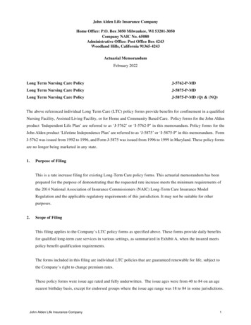
ITG-3050 Product SpecificationRecommended Power-on ProcedureAll Voltages at 0V4.4Document Number: PS-ITG-3050-00Revision: 1.3Release Date: 08/25/2011Power-Up Sequencing1. TVDDR is VDD rise time: Time for VDD torise from 10% to 90% of its final valueTVDDR2. TVDDR is 5ms90%VDD3. TVLGR is VLOGIC rise time: Time forVLOGIC to rise from 10% to 90% of itsfinal value10%TVLGR4. TVLGR is 1ms90%VLOGIC5. TVLG-VDD is the delay from the start ofVDD ramp to the start of VLOGIC rise10%6. TVLG-VDD is 0ms; VLOGIC amplitudemust always be VDD amplitude7. VDD and VLOGIC must be monotonicrampsTVLG - VDD17 of 42
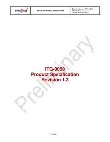
ITG-3050 Product Specification5Document Number: PS-ITG-3050-00Revision: 1.3Release Date: 08/25/2011Functional Overview5.1Block Diagram1CLKINCLKOUTCLOCK22X nditioningADCFIFO89PrimaryI2C SerialInterface2324Y GyroZ tioningADCSensorRegisterSecondaryI2C SerialInterfaceSe
3050's FIFO and then go into a low-power sleep mode while the device collects more data. The ITG-3050 features a 3-axis digital gyro with programmable full-scale ranges of 250, 500, 1000, and 2000 degrees/sec (dps or /sec), which is useful for precision tracking of both fast and slow motions. Rate