Transcription
ASCE 7-103D Wind Loading1
All information in this document is subject to modification without prior notice. No part or thismanual may be reproduced, stored in a database or retrieval system or published, in any formor in any way, electronically, mechanically, by print, photo print, microfilm or any other meanswithout prior written permission from the publisher. Scia is not responsible for any direct orindirect damage because of imperfections in the documentation and/or the software. Copyright 2014 Scia Group nv. All rights reserved.2
Introduction. 4Wind setup . 5Wind data . 6Directional procedure – External pressure zones .7Envelope procedure – External pressure zones . 15Internal pressure coefficient . 24Wind load combination . 25Design wind load . 263
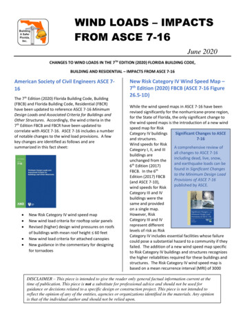
IntroductionThis document briefly explains the upgrade to the 3D wind loading module for IBC code inScia Engineer versions 14.1 or later. This document should be read in conjunction with the 3Dwind loading - Theoretical Background which gives the basis of the calculation along with thescope and the assumptions.The American Society of Civil Engineers (ASCE) released a new Minimum Design Loads forBuildings and Other Structures document in 2010 and the code went into effect with theadoption of IBC 2012. The ASCE 7-10 document includes changes to the determination andapplication of wind loading on structures as well as the load combinations used for theseloads. Scia Engineer 2014.1 supports wind load generation to ASCE 7-10 enabling users todesign for the most current wind loading code. The working of the new method is explained inthe subsequent sections.The major differences between ASCE 7-05 and ASCE 7-10 in the context of wind loading are: Low rise method is now referred to as Envelope procedure; All heights method is now referred to as Directional procedure; New wind speed maps with increased wind speeds for most areas; Use of Gust factor, G 0.85 for all structures within both the low rise and all heightsmethods; The Importance factor, I, based on the occupancy category of the structure is no longerincluded in the calculation of the velocity pressure; For Low Rise method (Envelope procedure), the external pressure coefficients (GCpf)and the wind zones have changed and are now included in two wind load cases:Load case ‘A’ (wind perpendicular to the roof ridge) and Load case ‘B’ (wind parallel toroof ridge). Changes to load combinations for wind loading for both Load and Resistance factorDesign (LRFD) and Allowable Stress Design (ASD).The items which have been implemented in Scia Engineer are, the change of method names,new calculation procedure for Envelope Procedure and new set of load combinations forASCE 7-10.4
Wind setupThe wind setup data has a new option to select between ASCE 7-05 and ASCE 7-10.Based on the code selected the structure classification will point to the appropriate method(Directional / Envelope Vs All heights / Low rise). The calculation methods in Add Wind LoadCases dialog also uses the corresponding name.Importance factor ‘I’ is available with ASCE 7-05 only as required by the code.5
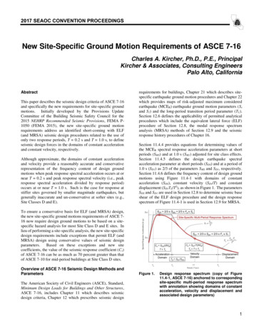
Wind dataIn order to facilitate expected external pressure zones generation new inputs are added in thewind data of a 2D member / Load panel with ASCE 7-10 Envelope Procedure.Wind data on a Wall, has an input for Wall to roof ridge relation. The user can select betweenperpendicular and parallel options depending upon how the building is modelled. Wind dataon a Flat roof has an option to Swap longitudinal direction. The inputs are particularly usefulfor complex building shapes where the data is not readily accessible from the model. Thezones generated will vary depending upon the inputs. This is explained through an example inthe subsequent sections of this document.The picture above shows an example of a duo-pitch roof model where the wall to roof ridgerelation is set to parallel for ‘S1’ and ‘S5’ and perpendicular for ‘S6’ and ‘S2’6
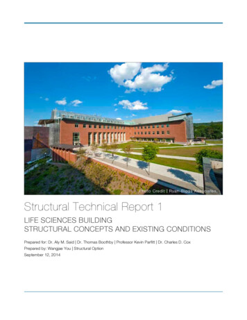
Directional procedure – External pressure zonesThe Directional Procedure (ASCE 7-10 Chapter 27) is applicable for building of all heights.The external pressure coefficients for this method are based on past wind tunnel testing ofprototypical building models for the corresponding direction of wind.The Directional Procedure implemented in Scia Engineer is based on Section 27.4.1 of thecode applicable for enclosed and partially enclosed buildings only.Chapter 26 of ASCE 7-10 defines a partially enclosed building as a building that complies withboth of the following conditions: The total area of openings in a wall that receives positive external pressure exceeds the sum of theareas of openings in the balance of the building envelope (walls and roof) by more than 10%. The total area of openings in a wall that receives positive external pressure exceeds 4 ft2 (0.37 m2)or 1% of the area of that wall, whichever is smaller, and the percentage of openings in the balanceof the building envelope does not exceed 20%.An open building is defined to have each wall at least 80% open. A building that does not comply withthe requirements for open or partially enclosed building is classified as enclosed building.It is possible to include up to 32 wind load cases considering positive and negative externaland internal pressure coefficients and torsional load cases. This is the same as in ASCE 7-05.7
The above picture shows all the possible 32 load cases where 0 , 90 , 180 and 270 represents the wind direction and ‘T’ represents Torsional load cases.Note that a 0o wind represents wind along the global X axis (positive direction).The external pressure zoning by the software is explained through an example below.8
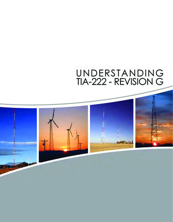
Directional Procedure example:A building with duo pitch roof is modelled as shown below.Building length 140 ftBuilding width 80 ftHeight to eaves 45 ftHeight to ridge 60 ftFor simplicity 8 load cases will be generated for this example (excluding the torsional loadcases and –Cpi combinations)9
Roof angle 20.56oL/B for wind normal to ridge 80/140 0.57L/B for wind parallel to ridge 140/80 1.75h/L for wind normal to ridge 52.5/80 0.65625External pressure coefficients from figure 27.4-1:Windward wall coefficient 0.8Leeward wall coefficient for wind normal to ridge -0.5Leeward wall coefficient for wind parallel to ridge -0.35Side wall coefficient -0.7Roof pressure coefficient for wind normal to ridge and windward -0.48 & -0.03Roof pressure coefficient for wind normal to ridge and leeward -0.6Roof pressure coefficient for wind parallel to ridge:Zone 1 from 0 to 26.25 ft with Cpe -0.9 and -0.18Zone 2 from 26.25 to 52.5 ft with Cpe -0.9 and -0.18Zone 3 from 52.5 to 105 ft with Cpe -0.5 and -0.18Zone 4 from 105 to 140 ft with Cpe -0.3 and -0.18External pressure zones created in Scia Engineer after invoking Run generator is shownbelow:Load case: 3Dwind1, 0, CPE, CPIWind direction 0 represents wind along global X hence it is wind normal to ridge. Note thatthis will change if the building is rotated.10
Load case: 3Dwind2, 0, -CPE, CPI3DWind2 is similar to 3DWind1 with alternative windward roof pressure coefficient of -0.48Note that a negative coefficient indicates load acting away from the surface (suction).11
Load case: 3Dwind5, 180, CPE, CPI and 3Dwind6, 180, -CPE, CPIWind direction 180 represents wind from –X direction. Hence the zones for load case3DWind5 and 3DWind6 will be similar to 3DWind1 and 3DWind2 but with the windward andleeward faces swapped.12
Load cases: 3Dwind3, 90, CPE, CPI & 3Dwind4, 90, -CPE, CPILoad cases 3DWind3 and 3DWind4 represent wind along global Y direction i.e. wind parallelto the ridge hence has 4 zones (0 to h/2, h/2 to h, h to 2h and 2h) as shown below.Load cases: 3Dwind7, 270, CPE, CPI & 3Dwind8, 270, -CPE, CPILoad cases 3DWind7 and 3DWind8 are similar to 3DWind3 and 3DWind4 but with windwardand leeward faces swapped.13
Note that the free loads created after invoking Run generator does not have a proper sign asit is not assigned to any particular member. The project has to be calculated OR the loadsgenerated on to the members to verify the actual load direction.When the building is rotated by 90o the X wind (0o wind) becomes wind parallel to the ridgehence the zoning will change accordingly for all the load cases.Similar working can be observed with other roof types such as flat, mono-pitch or hipped roof.14
Envelope procedure – External pressure zonesThe Envelope Procedure (ASCE 7-10 Chapter 28) is applicable for low rise buildings. Chapter26 of ASCE 7-10 defines low-rise buildings as enclosed or partially enclosed buildings inwhich the mean roof height is less than or equal to 60 ft and the mean roof height does notexceed least horizontal dimension.In this method the pseudo-external pressure coefficients are derived from past wind tunnel testing ofprototypical building models successively rotated through 360o, such that the pseudo-pressure casesproduce key structural actions (uplift, horizontal shear, bending moments, etc.) that envelop theirmaximum values among all possible wind directions.With this method it is possible to include up to 32 wind load cases considering two referencecorners for each wind direction with positive, negative internal pressure coefficients andtorsional load cases.The above picture shows all the possible 32 load cases where 0 , 90 , 180 and 270 represent the wind direction, ‘T’ represents Torsional load cases and ‘R1’ and ‘R2’ representthe reference corners in detailed in Figure 28.4-1.15
The external pressure zoning with the Envelope Procedure is explained through the samebuilding with duo-pitch roof discussed within the Directional Procedure.Note that the special zoning for hipped roofs presented in commentary Figure C28.4-1 is notsupported in Scia Engineer 2014.1.Envelope Procedure – Duo-pitch roof example:Building length 140 ftBuilding width 80 ftHeight to eaves 45 ftHeight to ridge 60 ftAs with Directional Procedure 8 load cases will be generated for this example (excluding thetorsional load cases and –Cpi combinations)16
External pressure coefficients from figure 28.4-1:Roof angle 20.56oZone coefficients for load case ‘A’ (wind normal to the ridge):Roofangle20.56oZone 1EZone 1Windward walledge zoneWindward wallmain zone0.79Zone 4EZone 4Leeward walledge zone0.53Leeward wallmain zone‐0.63‐0.43Note: No zones are created in the side walls with load case ARoofangle20.56oZone 2EZone 2Roof edge zonewindward sideRoof main zonewindward side‐1.0Zone 3EZone 3Roof edge zoneleeward sideRoof main zoneleeward side‐0.68‐0.48‐0.64Zone coefficients for load case ‘B’ (wind parallel to the ridge):Zone 5EZone 5Zone 6EZone 6Zone 1EZone 1Zone 4EZone 4RoofangleWindwardwall edgezoneWindwardwall mainzoneLeewardwall edgezoneLeewardwall mainzoneSidewalledge 5Roofangle20.56oZone 2ERoof edge zonewindward side‐1.07Zone 2Roof main zonewindward side‐0.29Zone 3EZone 3Roof edge zoneleeward sideRoof main zoneleeward side‐0.53‐0.37‐0.6917
Half edge zone length, a Minimum (0.1*80, 0.4*52.5) 8 ftThe external pressure zoning logic implemented in Scia Engineer for the Envelope Procedureis summarised below: A windward wall parallel to the ridge will have zones 1 and 1E from load case ‘A’ A leeward wall parallel to the ridge will have zones 4 and 4E from load case ‘A’ A sidewall perpendicular to the ridge will have no zones according to load case ‘A’ A windward wall perpendicular to the ridge will have zones 5 and 5E from load case ‘B’ A leeward wall perpendicular to the ridge will have zones 6 and 6E from load case ‘B’ A sidewall parallel to the ridge will have zones 1 and 1E near the reference corner and 4& 4E away from the reference corner. Roof will have zones 2 and 2E near the reference corner and 3 & 3E away from thereference corner.External pressure zones created in Scia Engineer after invoking Run generator for themethod is shown below. The reference corner in each case is marked with a red circle below.With the current example 0o and 180o wind will create load case A zones and 90o and 270owind will create load case B zones. If the building is rotated through 90o you will observe thatthe load cases are swapped i.e. 0o & 180o wind will create load case B zones and 90o windand 270o wind will create load case A zones.Load case: 3DWind1 – Wind R1, 0, CPE, CPILoad case: 3DWind5 – R2, 0, CPE, CPI18
Wind direction: 0o (Wind from X direction)Wind direction: 0o (Wind from X direction)Reference corner, R2: (0, 140, 0)Reference corner, R1: (0, 0, 0)Load case A zones: Wall ‘S1’ is a windward wall with zones1 and 1E (Cpe 0.53 & 0.79)Wall ‘S1’ is a windward wall with zones 1and 1E (Cpe 0.53 & 0.79) Wall ‘S5’ is a leeward wall with zones 4and 4E (Cpe ‐0.43 & ‐0.63)Wall ‘S5’ is a leeward wall with zones 4and 4E (Cpe ‐0.43 & ‐0.63) Wall ‘S6’ and ‘S2’ are side walls with nozonesWall ‘S6’ and ‘S2’ are side walls with nozones Roof ‘S3’ has zones 2 and 2E (Cpe ‐0.64 and ‐1.0)Roof ‘S3’ has zones 2 and 2E (Cpe ‐0.64and ‐1.0) Roof ‘S4’ has zones 3 and 3E (Cpe ‐0.48& ‐0.68)Load case A zones: Roof ‘S4’ has zones 3 and 3E (Cpe ‐0.48& ‐0.68)19
Load case: 3DWind3 – Wind R1, 180, CPE, CPILoad case: 3DWind7 – Wind R2, 180, CPE, CPIWind direction: 180o (Wind from ‐X direction)Wind direction: 180o (Wind from ‐X direction)Reference corner, R1: (80, 140, 0)Reference corner, R2: (80, 0, 0)Load case A zones:Load case A zones: Wall ‘S1’ is a leeward wall with zones 4and 4E (Cpe ‐0.43 & ‐0.63) Wall ‘S5’ is a windward wall with zones1 and 1E (Cpe 0.53 & 0.79) Wall ‘S6’ and ‘S2’ are sidewalls with nozones Roof ‘S3’ has zones 3 and 3E Wall ‘S1’ is a leeward wall with zones 4and 4E (Cpe ‐0.43 & ‐0.63) Wall ‘S5’ is a windward wall with zones 1and 1E (Cpe 0.53 & 0.79) Wall ‘S6’ and ‘S2’ are sidewalls with nozones Roof ‘S3’ has zones 3 and 3E(Cpe ‐0.48 & ‐0.68)(Cpe ‐0.48 & ‐0.68)20
Roof ‘S4’ has zones 2 and 2E(Cpe ‐0.64 & ‐1.0)Load case: 3DWind4 – Wind R1, 270, CPE, CPIoWind direction: 270 (Wind from ‐Y direction)Reference corner, R1: (0, 140, 0)Load case B zones: Wall ‘S1’ is a sidewall with zones 1 and1E (Cpe ‐0.45 & ‐0.48) Wall ‘S5’ is a sidewall with zones 4 and4E (Cpe ‐0.45 & ‐0.48) Wall ‘S6’ is a leeward wall with zones 6and 6E (Cpe ‐0.29 & ‐0.43)Roof ‘S4’ has zones 2 and 2E(Cpe ‐0.64 & ‐1.0)Load case: 3DWind8 – Wind R2, 270, CPE, CPIWind direction: 270o (Wind from ‐Y direction)Reference corner, R2: (80, 140, 0)Load case B zones:21 Wall ‘S1’ is a sidewall with zones 1 and1E (Cpe ‐0.45 & ‐0.48) Wall ‘S5’ is a sidewall with zones 4 and4E (Cpe ‐0.45 & ‐0.48) Wall ‘S6’ is a leeward wall with zones 6and 6E (Cpe ‐0.29 & ‐0.43) Wall ‘S2’ is a windward wall with zones 5
and 5E (Cpe 0.40 & 0.61)Wall ‘S2’ is a windward wall with zones5 and 5E (Cpe 0.40 & 0.61) (Cpe ‐0.69 & ‐1.07)Roof ‘S3’ has zones 2 and 2E (Cpe ‐0.69 & ‐1.07) Roof ‘S3’ has zones 2 and 2ERoof ‘S4’ has zones 3 and 3E(Cpe ‐0.37 & ‐0.53)Roof ‘S4’ has zones 3 and 3E(Cpe ‐0.37 & ‐0.53)Mono‐pitch roof example:The pictures below show the zoning for the same building with mono‐pitch roof. The principles are the sameas explained in the previous example: A windward wall parallel to the ridge will have zones 1 and 1E from load case ‘A’ A leeward wall parallel to the ridge will have zones 4 and 4E from load case ‘A’ A sidewall perpendicular to the ridge will have no zones according to load case ‘A’ A windward wall perpendicular to the ridge will have zones 5 and 5E from load case ‘B’ A leeward wall perpendicular to the ridge will have zones 6 and 6E from load case ‘B’ A sidewall parallel to the ridge will have zones 1 and 1E near the reference corner and 4 & 4E away fromthe reference corner. Roof will have zones 2 and 2E near the reference corner and 3 & 3E away from the reference corner.Load case: 3DWind1 – Wind R1, 0, CPE, CPILoad case: 3DWind5 – Wind R2, 0, CPE, CPILoad case: 3DWind2 – Wind R1, 90, CPE, CPILoad case: 3DWind6 – Wind R2, 90, CPE, CPI22
Load case: 3DWind3 – Wind R1, 180, CPE, CPILoad case: 3DWind7 – Wind R2, 180, CPE, CPI23
Internal pressure coefficientThe internal pressure coefficients are defaulted based on the enclosure class set in the windsetup following Table 26.11-1 of ASCE 7-10.Enclosure classificationDefault internalpressure coefficientPartially enclosed buildings /‐ 0.55Enclosed buildings /‐ 0.1824
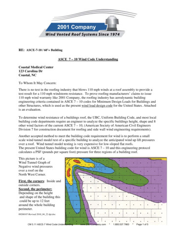
Wind load combinationThe following changes can be observed comparing the load combinations (involving wind)between ASCE 7-05 with ASCE 7-10:Load casesCombinationtypeCombinationASCE 7‐05 loadcombinationASCE 7‐10 loadcombinationD Dead loadLRFDcombinations11.2D 1.6(Lr or S or R) (L or 0.8W)1.2(D F) 1.6(Lr or Sor R) (L or 0.5W)Lr Roof liveload21.2D 1.6W L 0.5(Lror S or R)1.2(D F) 1.0W L 0.5(Lr or S or R)W Wind load30.9D 1.6W 1.6H0.9D 1.0W 1.6H1D H F (W or 0.7E)D H F (0.6W or0.7E)2D H F 0.75(W or0.7E) 0.75L 0.75(Lr orS or R)D H F 0.75(0.6W) 0.75L 0.75(Lr or S orR)30.6D W H0.6D 0.6W HL Live loadS Snow loadR Rain loadH Lateralearth pressureF Load dueto fluidsASDcombinationsChoosing ASCE 7-10 in the code setup will generate load combinations with appropriatefactors with automatic load combination generation.25
Design wind loadThe external pressure coefficients are combined with the internal pressures to obtain thedesign wind loading according to expression 27.4-1 for Directional Procedure and 28.4-1 forEnvelope Procedure.Note that, with the Directional Procedure Figure 27.4-1 gives just the external pressurecoefficient (Cp) whereas Figure 28.4-1 of the Envelope Procedure gives a combined gusteffect factor and external pressure coefficient (GCp).26
The American Society of Civil Engineers (ASCE) released a new Minimum Design Loads for Buildings and Other Structures document in 2010 and the code went into effect with the adoption of IBC 2012. The ASCE 7-10 document includes changes to the determination and application of wind loading on s