Transcription
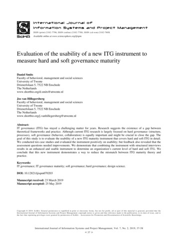
Page 1 of 9 ITG-3200 Hookup GuideIntroductionThis is a breakout board for InvenSense’s ITG-3200, a groundbreakingtriple-axis, digital output gyroscope. The ITG-3200 features three 16-bitanalog-to-digital converters (ADCs) for digitizing the gyro outputs, a userselectable internal low-pass filter bandwidth, and a Fast-Mode I2C (400kHz)interface. Additional features include an embedded temperature sensor anda 2% accurate internal oscillator.This tutorial will help you get started using the ITG-3200 in your nextproject. We will cover the hardware, discuss the code briefly, then show youhow to hook it up to a microcontroller.Suggested ReadingThis tutorial builds on some basic concepts. If you are unfamiliar with any ofthe topics below, go ahead and check them out. We’ll be right here waiting. What is Arduino?Gyroscope BasicsI2C CommunicationSerial Terminal BasicsHow to SolderBreadboard BasicsHardware OverviewPowerThe ITG-3200 can be powered at anywhere between 2.1 and 3.6V. Forpower supply flexibility, the ITG-3200 has a separate VLOGIC reference pin(labeled VIO), in addition to its analog supply pin (VDD), which sets the
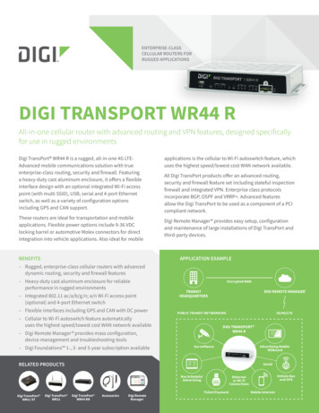
Page 2 of 9logic levels of its serial interface. The VLOGIC voltage may be anywherefrom 1.71V min to VDD max. For general use, VLOGIC can be tied to VCC.The normal operating current of the sensor is just 6.5mA.CommunicationCommunication with the ITG-3200 is achieved over a two-wire (I2C)interface. The sensor also features a interrupt output and an optional clockinput.Clock Source JumperIn the next picture, you can see a small jumper next to the pin labeled‘CLK.’ The ITG-3200 has a feature that allows you to connect an externalclock. Unless you plan to use an external clock, you need to ‘close’ thisjumper by connecting the two pads with solder. If you’re following thistutorial and using the provided example code, go ahead and close thejumper.Make sure you close this jumper with solder if you’re NOT using anexternal clock source.I2C Address JumperA jumper on the top of the board allows you to easily select the I2C address,by pulling the AD0 pin to either VCC or GND; the board is shipped with thisjumper tied to VCC.I2C Pull-up ResistorsNote that there are two unpopulated pull-up resistors on the I2C lines.These can be added later by the user if desired.Here the I2C address jumper (top) and the unpopulated I2C pull-up resistors(bottom) are highlighted.Hooking it Up
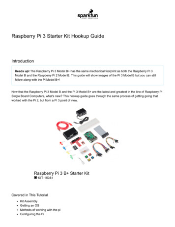
Page 3 of 9There are only two considerations for assembling the ITG-3200 breakout:what to do for the headers, and whether or not you’re going to use anexternal clock source for the ITG-3200.For the headers you have a couple options, you can solder in male orfemale 0.1" headers, or you can just solder wires directly to the holes in thebreakout board. In this example, male headers are soldered to the breakoutboard to make it easy to attach to a breadboard. Then, we’ll be hooking theITG-3200 up to an Arduino Leonardo using some male-to-male jumperwires.Second, since we will not be using an external clock source in this setup,make sure the CLKIN jumper on the bottom of the ITG-3200 is closed witha blob of solder.Here’s everything all hooked up. Make sure you add the small jumper fromVDD to VIO to ensure they are both connected to 3.3V.The SDA and SCL pins should be present on most Arduinos. Older, prerev3 Arduinos might not have SCL and SDA pins. In that case, connectSDA to A4 and SCL to A5.The ITG3200 sensor is a 3.3V device. This means that the sensor shouldbe powered by 3.3V and the communication signals should be between 0Vand 3.3V. The Arduino Leonardo (and other similar boards) are 5V devices.Even though we power the board with the 3.3V output from the Arduino, thecommunication signals are still going to be 5V. Technically this should beavoided as it can cause damage to the sensor in the long run. Whenimplementing this gyro in a final project, it’s in your best interest to usesomething like a Logic Level Converter to change the voltages of thecommunication signals. You could also use an Arduino Pro (3.3V/8 MHz).However, for the purposes of testing out your gyro, using a 5V deviceshould work fine.That’s all there is to it! Now, let’s look at some code to get this gyro up andrunning.FirmwareWe’re finally ready to start looking at the firmware. We’ve written anexample Arduino sketch to help you get started. You can downloadfirmware from the ITG-3200 GitHub page.The sample sketch reads the gyroscope data for the X, Y, and Z axes andprints it to the serial port. This is raw gyroscope data, and it has not beenconverted to degrees per second yet. Bigger numbers mean the device isrotating faster. Positive numbers indicate one direction of rotation whilenegative numbers indicate the opposite rotation direction. Since this is atriple-axis gyroscope, we can measure the rotational rate of the board nomatter which way the board is rotating. Rotation is usually measured indegrees per second. If the board spins around an axis exactly one time in asecond, the gyroscope would measure 360 degrees per second.Now, let’s break up the code in to sections to go over what’s happening alittle more in depth.
Page 4 of 9//The Wire library is used for I2C communication#include Wire.h //This is a list of registers in the ITG 3200. Registers are parameters that determine how the sensor will behave, or they can hold data that represent the//sensors current status.//To learn more about the registers on the ITG 3200, downloadand read the datasheet.char WHO AM I 0x00;char SMPLRT DIV 0x15;char DLPF FS 0x16;char GYRO XOUT H 0x1D;char GYRO XOUT L 0x1E;char GYRO YOUT H 0x1F;char GYRO YOUT L 0x20;char GYRO ZOUT H 0x21;char GYRO ZOUT L 0x22;//This is a list of settings that can be loaded into the registers.//DLPF, Full Scale Register Bits//FS SEL must be set to 3 for proper operation//Set DLPF CFG to 3 for 1kHz Fint and 42 Hz Low Pass Filterchar DLPF CFG 0 1 0;char DLPF CFG 1 1 1;char DLPF CFG 2 1 2;char DLPF FS SEL 0 1 3;char DLPF FS SEL 1 1 4;//I2C devices each have an address. The address is defined inthe datasheet for the device. The ITG 3200 breakout board canhave different address depending on how//the jumper on top of the board is configured. By default, the jumper is connected to the VDD pin. When the jumper is connected to the VDD pin the I2C address//is 0x69.char itgAddress 0x69;This is the configuration section of the sketch. It looks more complicatedthan it is! First we include the “Wire.h” library, which comes standard withthe Arduino IDE. This library is used for I2C communication, which is thecommunication protocol used by the ITG-3200.Next, there is list of variables which are assigned to different registers onthe ITG-3200. Registers are used mostly to do two things: configureparameters for a sensor, or hold data that the sensor has collected. Whenwe want to interact with a sensor’s register, we must tell the sensor whichregister address we want to work with. After the list of registers is a shortlist of register parameters. This is only a list for the parameters used by thissketch. There are many more parameters listed in the ITG-3200 datasheetthat aren’t used in this example.Finally, after the list of parameters, is the itgAddress variable. This is theI2C address of the ITG-3200. The I2C address for the sensor is also listed inthe datasheet. Remember, this address is directly impacted by theconfiguration of the solder jumper on the top of the PCB.
Page 5 of 9//In the setup section of the sketch the serial port will be configured, the i2c communication will be initialized, and theitg 3200 will be configured.void setup(){//Create a serial connection using a 9600bps baud rate.Serial.begin(9600);//Initialize the I2C communication. This will set the Arduino up as the 'Master' device.Wire.begin();//Read the WHO AM I register and print the resultchar id 0;id itgRead(itgAddress, 0x00);Serial.print("ID: ");Serial.println(id, HEX);//Configure the gyroscope//Set the gyroscope scale for the outputs to / 2000 degrees per seconditgWrite(itgAddress, DLPF FS, (DLPF FS SEL 0 DLPF FS SEL 1 DLPF CFG 0));//Set the sample rate to 100 hzitgWrite(itgAddress, SMPLRT DIV, 9);}The Setup section of the code is pretty short. First, we create a Serialconnection so that we can print data to a terminal window. Then weinitialize the I2C communication protocol. Now the Arduino is ready to startinteracting with the ITG-3200. Most sensors have some kind ofidentification register. A good way to verify that the communication isworking properly is to read the identification register and ensure the result isvalid. After reading the identification register a couple of values are writtento some registers on the ITG-3200 to configure the gyroscope to read dataat 100hz and measure rotation rates up to 2000 degrees per second. TheitgRead and itgWrite functions will be explained a little later. Once thedevice has been configured the actual gyroscope data can be read.//The loop section of the sketch will read the X,Y and Z output rates from the gyroscope and output them in the Serial Terminalvoid loop(){//Create variables to hold the output rates.int xRate, yRate, zRate;//Read the x,y and z output rates from the gyroscope.xRate readX();yRate readY();zRate readZ();//Print the output rates to the terminal, seperated by a TAB ln(zRate);//Wait 10ms before reading the values again. (Remember, theoutput rate was set to 100hz and 1reading per 10ms 100hz.)delay(10);}
Page 6 of 9The Loop section of the code is usually the ‘meat’ of the sketch, in this casethe loop is very straightforward. The sketch reads the X, Y, and Zgyroscope values using the readX(), readY() and readZ() functions. Afterstoring these values, they are printed to the serial terminal. We delay 10 msat the end of the loop so that we don’t try reading information from thesensor faster than it can be provided. For the Setup and Loop sections ofthe code to look so simple we had to use a couple of functions, let’s seehow the functions work.
Page 7 of 9//This function will write a value to a register on the itg 3200.//Parameters:// char address: The I2C address of the sensor. For the ITG 3200 breakout the address is 0x69.// char registerAddress: The address of the register on the sensor that should be written to.// char data: The value to be written to the specified register.void itgWrite(char address, char registerAddress, char data){//Initiate a communication sequence with the desired i2c deviceWire.beginTransmission(address);//Tell the I2C address which register we are writing toWire.write(registerAddress);//Send the value to write to the specified registerWire.write(data);//End the communication sequenceWire.endTransmission();}//This function will read the data from a specified register on the ITG 3200 and return the value.//Parameters:// char address: The I2C address of the sensor. For the ITG 3200 breakout the address is 0x69.// char registerAddress: The address of the register on the sensor that should be read//Return:// unsigned char: The value currently residing in the specified registerunsigned char itgRead(char address, char registerAddress){//This variable will hold the contents read from the i2c device.unsigned char data 0;//Send the register address to be read.Wire.beginTransmission(address);//Send the Register AddressWire.write(registerAddress);//End the communication sequence.Wire.endTransmission();//Ask the I2C device for om(address, 1);//Wait for a response from the I2C deviceif(Wire.available()){//Save the data sent from the I2C devicedata Wire.read();}//End the communication sequence.Wire.endTransmission();//Return the data read during the operationreturn data;}//This function is used to read the X Axis rate of the gyroscope. The function returns the ADC value from the Gyroscope
Page 8 of 9//NOTE: This value is NOT in degrees per second.//Usage: int xRate readX();int readX(void){int data 0;data itgRead(itgAddress, GYRO XOUT H) 8;data itgRead(itgAddress, GYRO XOUT L);return data;}//This function is used to read the Y Axis rate of the gyroscope. The function returns the ADC value from the Gyroscope//NOTE: This value is NOT in degrees per second.//Usage: int yRate readY();int readY(void){int data 0;data itgRead(itgAddress, GYRO YOUT H) 8;data itgRead(itgAddress, GYRO YOUT L);return data;}//This function is used to read the Z Axis rate of the gyroscope. The function returns the ADC value from the Gyroscope//NOTE: This value is NOT in degrees per second.//Usage: int zRate readZ();int readZ(void){int data 0;data itgRead(itgAddress, GYRO ZOUT H) 8;data itgRead(itgAddress, GYRO ZOUT L);return data;}There are five functions in this sketch, but three of them are very similar.The first function, itgWrite() , is used to write a value to a register on theITG-3200. To use this function three parameters must be provided: theaddress, the registerAddress, and the data. The address is the I2C addressof the sensor. As it turns out, more than one sensor can be connected totheI2C pins at the same time. In order for the sensors to know who issupposed to be getting the data, they each have a unique address. That’swhat we’re providing with the ‘address’ parameter. The second parameteris the registerAddress. Like we discussed earlier, most sensors have a setof registers, and each register has it’s own address. The last parameter isthe data to be written to the address. We can configure a parameter on asensor by writing data to a register address.The next function is the itgRead() function. This function allows us to readthe data stored in the register of a sensor. The itgRead function requirestwo parameters, and it returns a character value. The parameters aresimilar to those in the itgWrite() function; the address is the I2C addressof the sensor we want to read from, and the registerAddress is the addressof the register we want to read. The function will send the contents of theregister back.Running the SketchOnce you’ve connected the ITG-3200 breakout board to the Arduino youcan upload the ITG3200 Basic Arduino sketch. To see the data from thegyroscope, just open the serial terminal with a baud rate setting of 9600.You’ll see values start streaming through the terminal window almost
Page 9 of 9immediately. On each line of the terminal, there are three values: x, y, and zrotation values. Remember, we didn’t convert this data to degrees persecond so the values that are being streamed are the ADC values from theITG-3200. You may also notice that even if the gyroscope is sitting still (notrotating in any direction) the values aren’t reporting 0. This is because thereis an inherent bias in the gyroscope. To get accurate measurements you’llneed to calibrate the readings. You can do this in the sketch by reading thevalues output from the sensor while it is sitting still and storing them intosome variables. Then later, when the sensor values are being read, justoffset the readings by the calibration values.Resources and Going FurtherYou should now have a good understanding of how the ITG-3200 works.Now get out there and make some cool projects! If you need more info onthe ITG-3200, make sure you check out the datasheet.Want to learn more about gyroscopes? Check out our buying guide to learnabout all the variteies SparkFun 200-hookup-guide? ga 1.43014117.1939456957. 10/8/2015
ITG-3200 Hookup Guide Introduction This is a breakout board for InvenSense's ITG-3200, a groundbreaking triple-axis, digital output gyroscope. The ITG-3200 features three 16-bit analog-to-digital converters (ADCs) for digitizing the gyro outputs, a user-selectable internal low-pass filter bandwidth, and a Fast-Mode I C (400kHz) interface.