Transcription
Quick Start Guide00825-0100-3104, Rev AAJune 20223410/3810 Series Local Display FieldInstall Kit
Quick Start GuideFebruary 2022Safety and approval informationThis Rosemount product complies with all applicable European directives when properly installed inaccordance with the instructions in this manual. Refer to the EU declaration of conformity for directivesthat apply to this product. The EU declaration of conformity, with all applicable European directives,and the complete ATEX Installation Drawings and Instructions are available on the internet atwww.emerson.com or through your local Emerson support center.Information affixed to equipment that complies with the Pressure Equipment Directive, can be foundon the internet at http://www.emerson.com.For hazardous installations in Europe, refer to standard EN 60079-14 if national standards do not apply.Other informationFull product specifications can be found in the product data sheet. Troubleshooting information can befound in the user manual. Product data sheets and manuals are available from the Emerson website athttp://www.emerson.com.Return policyFollow Emerson procedures when returning equipment. These procedures ensure legal compliancewith government transportation agencies and help provide a safe working environment for Emersonemployees. Emerson will not accept your returned equipment if you fail to follow Emerson procedures.Return procedures and forms are available on our web support site at Emerson.com, or by phoning theEmerson Customer Service department.Emerson Flow customer serviceEmail: Worldwide: http://flow.support@emerson.com Asia-Pacific: http://APflow.support@emerson.comTelephone:2North and South AmericaEurope and Middle EastAsia PacificUnited States800 522 6277U.K.0870 240 1978Australia800 158 727Canada 1 303 527 5200TheNetherlands 31 (0) 704 136666New Zealand099 128 804Mexico 41 (0) 41 7686111France0800 917 901India800 440 1468Argentina 54 11 4837 7000Germany0800 182 5347Pakistan888 550 2682Brazil 55 15 3413 8000Italy8008 77334China 86 21 2892 9000Central &Eastern 41 (0) 41 7686111Japan 81 3 5769 6803Russia/CIS 7 495 981 9811South Korea 82 2 3438 4600Egypt0800 000 0015Singapore 65 6 777 8211Oman800 70101Thailand001 800 441 6426Qatar431 0044Malaysia800 814 008Kuwait663 299 01South Africa800 991 390Saudi Arabia800 844 9564Local Display Field Install Kit
February 2022North and South AmericaQuick Start GuideEurope and Middle EastUAEQuick Start GuideAsia Pacific800 0444 06843
Quick Start GuideFebruary 2022Signal words and symbolPay special attention to the following signal words, safety alert symbols and statements:Safety alert symbolThis is a safety alert symbol. It is used to alert you to potential physical injury hazards. Obey all safetymessages that follow this symbol to avoid possible injury or death.DANGERDanger indicates a hazardous situation which, if not avoided, will result in death or serious injury.WARNINGWarning indicates a hazardous situation which, if not avoided, could result in death or serious injury.CAUTIONCaution indicates a hazardous situation which, if not avoided, could result in minor or moderate injury.NOTICENotice is used to address safety messages or practices not related to personal injury.ImportantImportant is a statement the user needs to know and consider.TipTip provides information or suggestions for improved efficiency or best results.NoteNote is “general by-the-way” content not essential to the main flow of information.ContentsComponent disassembly. 5Component assembly. 104Local Display Field Install Kit
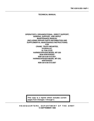
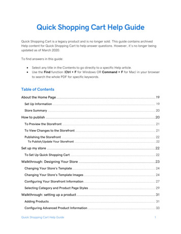
February 2022Quick Start Guide1Component disassembly1.1Local display field install kit includesA.B.C.D.E.F.G.H.LCD display boardLCD display shroudPan HD screw PH SEMS #6-32 X .38 M/S W/410 EXT 18-8 SSTLCD moduleCover – HSG LCD type FB100O-ring #2-245Backplane board 3410/3810Pan HD screw PH SEMS #6-32 X .88 Preassembled assemblies and parts:— LCD display board, shroud, LCD module— Cover – Housing (glass end cap) with O-ring— Backplane board— Pan HD screws #6-32 X .881.2Local display field install kit parts listItem(1)QuantityDescriptionPreassembled:LCD display field install kitQuick Start Guide5
Quick Start GuideFebruary 2022Item(1)QuantityDescriptionA1LCD display boardB1LCD display shroudC2Pan HD screw PH SEMS #6-32 X .38 M/S W/410 EXT18-8 SSTD1LCD modulePreassembled:E1Cover – HSG LCD type FB100F1O-ring #2-245G1Backplane board 3410/3810H4Pan HD screw PH SEMS #6-32 X .88(1) Item numbers correlate with DMC-009079 - 3410/3810 Series LCD Module1.3Check firmware version before powering off the meterApplication options: MeterLink AMS Device Manager6Local Display Field Install Kit
February 2022Quick Start Guide Field Communicator Requirements: Firmware Version 1.06 and Uboot Version January 31,2013 or later If necessary to upgrade firmware— Open MeterLink and connect to the meter— Open an Internet browser— Navigate to the Emerson website: emerson.com/Rosemount— Use Quick Links and click MeterLink Registration and Download toaccess the latest firmware— Go to MeterLink and use the Tools Program Download menu todownload a file to the meter. Click Open to display an OpenDownload File dialog. Select the desired file and click Open.MeterLink only downloads components that are different than whatis currently installed in the meter.1.4Remove power to the equipment and removetransmitter electronics enclosure endcaps Remove endcap security seals, if installed, and security latches. Remove power from equipment before removing endcaps if possibleand/or ensure explosive atmosphere is not present before opening thetransmitter electronics enclosure. Unplug CPU Module terminal board connectors (TB-1 and TB-2). Unplug I/O Module, and Power Supply terminal board connectors. Pull the CPU and I/O Modules from the enclosure.Quick Start Guide7
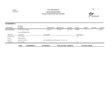
Quick Start GuideA.B.C.D.E.1.5February 2022CPU TB-2CPU TB-1I/O module connectors24V loop power10.4VDC - 36VDC powerRemove the backplane boardA. Backplane boardB. I.S. barrier boardC. Power supply board Remove four screws with lock washers. Pull Backplane from housing. Remove Power Supply and I.S. Barrier boards from Backplane.8Local Display Field Install Kit
February 20221.6Quick Start GuideDisconnect the acquisition cableA. Acquisition cableQuick Start Guide9
Quick Start Guide2Component assembly2.1Backplane board with 14 pin connectorFebruary 2022A. 14 pin connectorB. Backplane boardNoteCheck existing 3410/3810 Series Backplane board minimum for 14 pinconnector (J8).If equipped, use this board. If not, use board included with the Local DisplayField Install Kit.A. Acquisition cable Attach acquisition cable to backplane Tighten connector screws10Local Display Field Install Kit
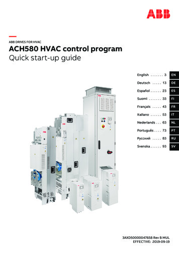
February 20222.2Quick Start GuidePlug power supply board and I.S. barrier module ontobackplane board with 14 pin connectorA. I.S. barrier boardB. Backplane boardC. Power supply board2.3Plug local display board into the backplane 14 pinconnectorA. 14 pin connectorB. Local display board Make sure LCD board is fully seated to backplane 14 pin connector.Quick Start Guide11
Quick Start Guide2.4February 2022Slide backplane, power supply, I.S. barrier module andlocal display module assembly into transmitter enclosureand fasten with 4 pan head screws. Make sure boards are aligned in the enclosure and I.S. barrier board isinside card cage key retainer. Use the long Pan HD Screws #6-32 X .88 provided with the kit.2.5Install endcap with sight glass Make sure endcap O-ring is installed.12Local Display Field Install Kit
February 2022Quick Start Guide2.6Reinstall CPU module and I/O module in the enclosure2.7Install CPU module TB-1 and TB-2 and I/O moduleterminal connectorsA. CPU TB-2B. CPU TB-1C. I/O module connectorsQuick Start Guide13
Quick Start Guide2.8February 2022If explosive atmosphere is not present, connect thepower supply terminal connectors and apply power tothe unitA. 24V loop powerB. 10.4VDC - 36VDC power Ensure all CPU LEDs are greenA. CPU LEDs Observe Local Display startup sequence (see Observe local displaystartup sequence)14Local Display Field Install Kit
February 20222.9Quick Start GuideIf explosive atmosphere is present, install endcaps andapply site power to equipmentA. Endcap security latch Reinstall endcap security latches Apply site powerNoteIf explosive atmosphere is present and site power initializes the unit, aService technician should observe the Local Display startup sequence (seeObserve local display startup sequence).2.10Observe local display startup sequenceA. Local displayB. Startup sequence – All segments displayed Two seconds after power up, the “Rosemount” logo appears at thebottom of the LCD screen. The Checksum displays.Quick Start Guide15
Quick Start GuideFebruary 2022 Make sure all segments are displayed (all the segments will come on andstay on for about 4 seconds). Pay careful attention and make sure that allsegments are functioning and no segments are missing. The Wait command displays, and then the four default Display Itemsscroll on the display.2.11Configure display items, measurement units, and scrolldelayConfiguration applications options: MeterLink - Field Setup Wizard AMS Device Manager Field Communicator Reference manuals:— HART Field Device Specification 3410 Series Gas Ultrasonic Meters— HART Field Device Specification 3810 Series Liquid Ultrasonic Meters— 3410 Series Gas Ultrasonic Meters Installation Manual— 3810 Series Liquid Ultrasonic Meters Installation Manual— 3812 Liquid Ultrasonic Meters Installation Manual16Local Display Field Install Kit
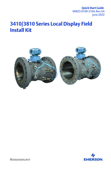
February 20222.12Quick Start GuideReinstall wire security seals on the endcaps, if necessaryInstallation completeA. 3410/3810 series transmitter with local displayQuick Start Guide17
Quick Start Guide18February 2022Local Display Field Install Kit
February 2022Quick Start GuideQuick Start Guide19
Quick Start Guide00825-0100-3104, Rev. AAJune 2022For more information: www.emerson.com 2022 Emerson. All rights reserved.Unauthorized duplication in whole or partis prohibited. Printed in the USA.The Emerson logo is a trademark andservice mark of Emerson Electric Co. Allother trademarks are the property of theirrespective companies.
C. Pan HD screw PH SEMS #6-32 X .38 M/S W/410 EXT 18-8 SST D. LCD module E. Cover - HSG LCD type FB100 F. O-ring #2-245 G. Backplane board 3410/3810 . — 3812 Liquid Ultrasonic Meters Installation Manual. Quick Start Guide February 2022 16 Local Display Field Install Kit. 2.12 Reinstall wire security seals on the endcaps, if necessary.