Transcription
Basics of Magnetics for Switching Power Webinar SeriesBasics of Power TransformersFebruary 12, 202010 AM CDT, 3 PM rWebinar ID: 198-288-883Presenter: George Slama, Wurth Electronics
Basics of Power TransformersGeorge SlamaSenior Application and Content EngineerWürth Elektronik
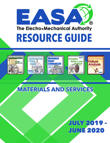
Today’s outline Continue from flyback ‘transformers’Magnetics everywherePrinciple of transformerEquivalent circuitLeakage inductance – couplingWinding capacitanceCore losses - ferriteWinding losses – Rdc - skin effect – proximity effectForward – unipolar – half the core – two switchPush-pull – bipolar - extra windingsHalf / full bridge – bipolar – good usage of core and windingsLLC – frequency regulation – almost idealSafety agency requirementsDate: 2020.02.12 PSMA Magnetics Committee Public Topic: Basics of Power TransformersMichael Faraday’s original induction ring, 1831Photo credit: Paul Wilkinson, Royal Institution3
Flyback ‘transformer’ By definition, as an energy storagedevice it’s an inductor The circuit operates this device as two VINseparate inductors that use the samecore to link them together. Because they are linked by the mutualflux, the voltages and currents havetransformer like property of turns ratio Because the input and output usedifferent windings it has the transformerproperty of galvanic isolation Transformer-chokeDate: 2020.02.12 PSMA Magnetics Committee Public Topic: Basics of Power TransformersT1D1VOUTC1S1Current, S1 clos edCurrent, S1 open4
Crossroads Inductor: An magnetic device that impedes the change in the flow of electric current by storing andreleasing energy from its magnetic field. Transformer: A magnetic device that transfers energy instantaneously through its magnetic field. Usedto change the voltage or current and provides galvanic isolation.1885Ottó Bláthy, Miksa Déri, Károly ZipernowskyDate: 2020.02.12 PSMA Magnetics Committee Public Topic: Basics of Power Transformers5
Magnetics everywhereSignal IsolationTransformerFilter InductorFilter InductorFilter InductorPower FactorCorrection InductorMain TransformerCommon ModeFilter InductorsDate: 2020.02.12 PSMA Magnetics Committee Public Topic: Basics of Power Transformers6
Galvanic isolationSafety isolation barrierInfineon app note AN 201702 PL83 007Date: 2020.02.12 PSMA Magnetics Committee Public Topic: Basics of Power Transformers7
Principle of a transformerVs Ns Vp NpNPDate: 2020.02.12 PSMA Magnetics Committee Public Topic: Basics of Power TransformersNSIs Np Ip Ns8
Add a source BV NAc tIPVPVSVs Ns Vp NpNSNP𝑋𝐿 2𝜋𝑓𝐿L 0 e N 2 AcBmax main fluxlc𝑉4𝑁𝐴𝑒𝑓(Square wave)Date: 2020.02.12 PSMA Magnetics Committee Public Topic: Basics of Power TransformersRight hand rule determine flux direction9
Add a load BV NAc tIPISVPVSNSNPRVs Ns Vp NpIs Np Ip Nsmain fluxDate: 2020.02.12 PSMA Magnetics Committee Public Topic: Basics of Power Transformers10
Add parasiticsintra & inter windingcapacitancesIPISVPVSNPNSleakage fluxleakage fluxmain fluxDate: 2020.02.12 PSMA Magnetics Committee Public Topic: Basics of Power TransformersR𝑘 1 𝑙𝑘𝑔𝐿11
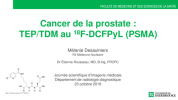
Equivalent circuit (lumped) Np:Ns – turns ratio (n)(note: either sidecan be the reference) Lm – magnetizing inductance Rc – core loss Lplkg, Lslkg – leakage inductance(usually combined into one) Rp, Rs – winding resistances – both acand dc Cp, Cs – intra winding capacitance Cps – interwinding capacitance Most element’s characteristics arefrequency dependentDate: 2020.02.12 PSMA Magnetics Committee Public Topic: Basics of Power TransformersCpsRpCpLplkgNp:NsRcLslk gLmRsCsThe secondary side elements of leakage inductance,resistance and capacitance can be transferred to theprimary by the square of the turns ratio.12
Leakage inductanceSolenoid 0 N AL lw2LeakageLlkg 0 N 2 Ains11 Ains MLT H ins H1 H 2 33 whereMLT mean length turnHins insulation thicknessH1 winding buildH2 winding buildlwDate: 2020.02.12 PSMA Magnetics Committee Public Topic: Basics of Power Transformers13
Effects of leakage inductance Delays power transferLimits rate of rise of the current waveform at turn-onAt turn-off causes voltage spike on drain of MOSFETAdds to secondary rectifier spikesDate: 2020.02.12 PSMA Magnetics Committee Public Topic: Basics of Power Transformers14
Reducting leakage inductance Only three soultions Reduce N2 by minimizing turns – most effective Reduce Ains bya) Keep the highest power windings next to each otherLlkgb) Minimize insulation thickness between windingsc) Avoid using shieldsd) Bifilar windings Increase lw bya) Use long winding lengths with few layersb) Split and interleave the one winding – one is most effectivec) Make winding lengths the same for all windingsd) Two coil series construction on C or U cores 0 N Ains2lw Techniques to reduce leakage inductance usually increase winding to winding capacitanceDate: 2020.02.12 PSMA Magnetics Committee Public Topic: Basics of Power Transformers15
Capacitance everywhere When a transformer is energized, different voltage gradientsarise almost everywhere Between turns Between layers Between windings Between terminals Between core and end of layer Between core and each terminal All these have capacitance which represents stored energynot used in the circuitDate: 2020.02.12 PSMA Magnetics Committee Public Topic: Basics of Power Transformers16
Effects of winding capacitance Slows the rise time of leading edge voltageCauses current spikes at turn onConducts noise – EMILimits operating frequency through self resonanced𝑙𝑤 𝑀𝐿𝑇𝐶 𝜖0 𝜀𝑟𝑑 0 8.854 10 12 F m w width of windingMLT mean length turnd distance between platesεr relative permittivityDate: 2020.02.12 PSMA Magnetics Committee Public Topic: Basics of Power Transformers17
Reducing winding capacitance Reduce permittivity εr by careful material selection Reduce A bya) Reduce winding length𝐴b) Do not interleave windings𝐶 𝜖0 𝜀𝑟 Increase d by𝑑a) Increase dielectric thicknessb) Use interlayer insulationc) Use heavier enamel insulationd) Do not wind bifilarqC Redistribute voltage and chargeVa) Use multiple section bobbinsb) Use Z winding – changes voltage distributionc) Use a faraday shield – drains charge Techniques to reduce capacitance usually end up increasing leakage inductanceDate: 2020.02.12 PSMA Magnetics Committee Public Topic: Basics of Power Transformers18
Core loss In applications it varies with FrequencyFlux levelTemperatureWaveform (including duty cycle)Power Loss vs peak fluxPower Loss Freq-Flux-Temp Curves are empirical derived frommeasurement normally of a sinewave Slope changes with frequency Most models pick just one spot onthe curvesSteinmetz equation𝑃 𝑘𝑓 𝛼 𝐵𝛽Date: 2020.02.12 PSMA Magnetics Committee Public Topic: Basics of Power TransformersCirca 189219
Ferrite core material First proposed by Hilpert in1909First invented by Kato & Takei in 1930First MnZn and NiZn by Sneok in 1945Core materials continue improve by tuningMaterial composition only affects Tc, Bsand crystalline anisotropy Structure sensitive properties are Hc, Brand permeabilityDate: 2020.02.12 PSMA Magnetics Committee Public Topic: Basics of Power Transformers20
Material optimizationHeck, C., Magnetic materials and their applications, Crane, Russak & Co., Inc., New York, 1974Date: 2020.02.12 PSMA Magnetics Committee Public Topic: Basics of Power Transformers21
You Pick Two Low power lossLow Power LossHigh BsatHigh FrequencyWide TemperatureVery high permeabilityA. Goldman, Modern Ferrite Technology, pg 101, from E.Roess, Advances in Ferrites, Vol 1Date: 2020.02.12 PSMA Magnetics Committee Public Topic: Basics of Power Transformers Panera Bread22
Performance factorSnoek’s limit - 1947Fig. 3 Frequency characteristic of ferrite µi and Snoek’s limit(TDK)(Ferroxcube)Date: 2020.02.12 PSMA Magnetics Committee Public Topic: Basics of Power Transformers23
Winding losses Governed by conservation of energy DC losses At low frequencies this is by minimizing I2R losses. AC losses At high frequencies it is by minimizing inductive energy that is energy transferred to and from the magnetic fieldgenerated by the current flow even if that results in higherI2R losses. Eddy currents Skin effect Proximity effectDate: 2020.02.12 PSMA Magnetics Committee Public Topic: Basics of Power TransformerslRdc APcu I R224
Skin effect o fr76 mmfDate: 2020.02.12 PSMA Magnetics Committee Public Topic: Basics of Power Transformers25
Promixity effect The proximity effect plays a far greater role in transformers because the neighboringconductors of a winding and neighboring windings generate fields which displace the current. It's possible to calculate approximate eddy current losses for simple geometries usingDowell’s curves.Two wires withcurrent in samedirectionDate: 2020.02.12 PSMA Magnetics Committee Public Topic: Basics of Power TransformersTwo wires withcurrent in oppositedirection26
Proximity effect For thick conductors h δ Along a winding the current concentrates onthe outer surfaces. Between primary and secondary the currentconcentrates on the facing surfaces.Image from en.wikipedia.orgDate: 2020.02.12 PSMA Magnetics Committee Public Topic: Basics of Power Transformers27
Magnetic fields in windings The core provides a low reluctance path for flux so the concentration of force isbetween the turns (blue lines) and builds with each turn enclosed by the pathloop. This force increases with each layer.Ni FFH lwDate: 2020.02.12 PSMA Magnetics Committee Public Topic: Basics of Power Transformers28
Power loss due to proximity effectd δ Let P1 be power loss in layer 1:3ΦP1 I R2rms2ΦΦ Power loss P2 in layer 2 is:2P2 I rmsR 2 I rms R 1P1 4 P1 5P12 Power loss P3 in layer 3 is:P3 2 I rms R 3I rms R 4 P1 9 P1 13P122 Power loss Pm in layer m is:Pm ((m 1) 2 m2 ) P1Date: 2020.02.12 PSMA Magnetics Committee Public Topic: Basics of Power Transformers29
MMF diagram The primary winding NI builds theMMF and the secondary winding NIreduces it back to zero.Ni FFH lwDate: 2020.02.12 PSMA Magnetics Committee Public Topic: Basics of Power Transformers30
Interleaved windings Interleaving reduces MMF and hence eddy current losses. One interleave is the mostpractical for power transformers.P2SP2P4S2P2S2P4MMFx0xWinding PortionsDate: 2020.02.12 PSMA Magnetics Committee Public Topic: Basics of Power Transformers31
Conversion to equivalent foilhdphhℎ hwlw𝜋𝑑4𝑁ℎ𝐹𝑙 𝑙𝑤 h Fl Reference: P.L. Dowell, “Effects of eddy currents in transformer windings”, Proc. Inst. Elect. Eng., vol. 113, no. 8, pp. 1387-1393, 1966Date: 2020.02.12 PSMA Magnetics Committee Public Topic: Basics of Power Transformers32
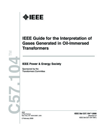
Basic equationé sinh(2A) sin(2A) 2(N 2 -1) sinh(A) - sin(A) ùRacFr Aê úRdccosh(2A)cos(2A)3cosh(A) cos(A)ëû34æp ö æ dö dA ç ç è 4ø èd ø pd bare wire diameterp wire pitchd skin depthN number of layersNlitz N k, where k number ofstrandsM. Kazimierczuk, High-frequency magnetic components, 2nd ed. Singapore: John Wiley & Sons, 2014, pp. 306-351.Date: 2020.02.12 PSMA Magnetics Committee Public Topic: Basics of Power Transformers33
Number of layersRacFr RdcNumber of layersDowell's curvesNormalizedDate: 2020.02.12 PSMA Magnetics Committee Public Topic: Basics of Power Transformers34
Forward converter True transformerOnly uses half the capability of the coreUses a separate output filter inductorUsually limited to 50% duty because coremust reset Separate reset winding High voltage on the switch – 2x Vin Limited by primary current to 100-200 W𝐵𝑚𝑎𝑥𝑉𝑝𝑘 𝑡𝑜𝑛 𝑁𝐴𝑐Date: 2020.02.12 PSMA Magnetics Committee Public Topic: Basics of Power Transformers35
Limited flux range – reset coreB400mT300mT200mT100mTHDate: 2020.02.12 PSMA Magnetics Committee Public Topic: Basics of Power Transformers36
Reset volt-second productSwitchingFrequency Usually the reset turns are equal to theprimary turns but this limits Ton to 50% max. By adjusting the turns ratio Np/Nr the ontime can be increased at the expense ofhigher reset voltage – Vdss on the switch. The reset voltage can be lower than Vdc butTon is reduced In all cases the volt second areas must beequal, A1 A2.𝑉𝑖𝑛 𝑇𝑜𝑛𝑁𝑝 𝑉𝑖𝑛 𝑇𝑟𝑁𝑟Date: 2020.02.12 PSMA Magnetics Committee Public Topic: Basics of Power 1Np/Nr(Vdc)VdcA1A237
Two switch forward Adding the second switch and diodesreduces the voltage stress on theswitch to Vin by clamping it and anyleakage inductance spikes to the rail. Needs a high side drive Automatic reset – no extra winding Rugged circuitDate: 2020.02.12 PSMA Magnetics Committee Public Topic: Basics of Power Transformers38
Push-pull Full usage of BH curvePoor utilization of winding areaOnly use half the windings at one timeEach half needs to support full voltageB𝐵𝑚𝑎𝑥𝑉𝑝𝑘 𝑡𝑜𝑛 2𝑁𝐴𝑐B-H loop ofnormaltransformerBmaxBBHBB-H loop ofcoreDate: 2020.02.12 PSMA Magnetics Committee Public Topic: Basics of Power Transformers39
Half bridge Full use of BH curve Full use of winding area C1, C2 split the input voltagewhich reduces the primaryturns count at the expense ofhigher currentDate: 2020.02.12 PSMA Magnetics Committee Public Topic: Basics of Power Transformers40
Full bridge Full use of BH curve Full use of winding area Used for highest power transferVINS1S3L1T1C1D1VOUTD2D3C2D4S2Date: 2020.02.12 PSMA Magnetics Committee Public Topic: Basics of Power TransformersS441
LLC converter Q1LRCRn:1:1D1 Full use of BH curveFull use of winding areaMore sinusoidal waveformsRegulation by variablefrequency-Q2COLMRLD2Date: 2020.02.12 PSMA Magnetics Committee Public Topic: Basics of Power Transformers42
Safety considerations Most transformers are used for isolation Therefore they must meet safety agency requirements These standards, like IEC 62368-1 which replace IEC 60950-1 impose minimumrequirements against defined hazards Electrical safety, energy safety, mechanical safety, heat – fire hazards, chemical hazards and radiation hazards Hazard based safety engineering – identify the source, the transfer mechanism andsafeguard For electrical safety that means minimum insulation thicknesses/layers plus creepage andclearance distances The new standard goes from prescriptive to performance oriented solutionsDate: 2020.02.12 PSMA Magnetics Committee Public Topic: Basics of Power Transformers43
Creepage and Clearance Creepage and clearanceare carefully defined ingreat detail The application dependson many factors whichinclude required safetylevel, working voltages,insulation material andthickness, environmentconditions, electricalenvironment, etc.Date: 2020.02.12 PSMA Magnetics Committee Public Topic: Basics of Power Transformers44
ApplicationTable 13 – Creepage, clearance, dti, MG IIIaCategoryMeasurementWorking voltagesType of insulationclearancecreepageThrough windingenamel or notP2 – Pollution degree 2P3 – Pollution degree 3dtiSolid insulation[thin sheet insulation]Source: IEC 61558-1, Page 1 of 3Date: 2020.02.12 PSMA Magnetics Committee Public Topic: Basics of Power Transformers45
Insulation systems Based on UL 1446 and IEC 61857Recognized componentCovers materials for motors andtransformers Plastic and electrical insulation materialsElectrical insulation systemsMagnet wire and magnet wire coatingsVarnishesSystem of predefined lists of materialsthat can be used together to meettemperature classes.Under gone long-term thermal aging andsealed-tube testing.Usually sponsored by an insulationvendor.Can be adopted for a fee.Date: 2020.02.12 PSMA Magnetics Committee Public Topic: Basics of Power Transformers
Conclusion Transformers appear to be simple devices madefrom some copper, insulation and a core The reality is that there is a lot going on under thecover that makes it work properly in a givenapplication Help, whether for components like cores andinsulation, design or finish parts is available frommany companies who are members of the PSMAThe art of magneticsDate: 2020.02.12 PSMA Magnetics Committee Public Topic: Basics of Power Transformers47
Thank youwww.psma.com
Photo credit: Paul Wilkinson, Royal Institution Michael Faraday's original induction ring, 1831. Date: 2020.02.12 PSMA Magnetics Committee Public Topic: Basics of Power Transformers . Limits rate of rise of the current waveform at turn-on . At high frequencies it is by minimizing inductive energy -