Transcription
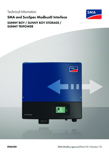
Technical InformationSMA and SunSpec Modbus InterfaceSUNNY BOY / SUNNY BOY STORAGE /SUNNY TRIPOWERENGLISHSMA-Modbus-general-TI-en-10 Version 1.0
Legal ProvisionsSMA Solar Technology AGLegal ProvisionsThe information contained in these documents is the property of SMA Solar Technology AG. Anypublication, whether in whole or in part, requires prior written approval by SMA Solar TechnologyAG. Internal reproduction used solely for the purpose of product evaluation or other proper use isallowed and does not require prior approval.SMA reserves the right to modify the implementation of communication interfaces and protocols atany time without notifying the user. It is the user’s responsibility to determine whether thedownloaded content is up to date and to comply with it. SMA shall not be held liable for anydamage as well as any assumption of consequential costs for customer systems by SMA that mayresult from the user’s failure to do so.Software licensesYou will find the software licenses for the installed software modules on the Internet at www.SMASolar.com.TrademarksAll trademarks are recognized, even if not explicitly identified as such. Missing designations do notmean that a product or brand is not a registered trademark.SMA Solar Technology AGSonnenallee 134266 NiestetalGermanyTel. 49 561 9522-0Fax 49 561 9522-100www.SMA.deEmail: info@SMA.deStatus: 5/24/2018Copyright 2018 SMA Solar Technology AG. All rights reserved.2SMA-Modbus-general-TI-en-10Technical Information
SMA Solar Technology AGTable of ContentsTable of Contents123Information on this Document.41.11.21.31.41.51.61.74444555Safety .62.12.22.36673.63.73.8Modbus Protocol.SunSpec Modbus Profile .SMA Modbus Profile .System Topology.Addressing and Data Transmission.3.5.1Unit IDs.3.5.2Query of Unit ID .3.5.3Register Address, Register Width and Data Block .3.5.4Data Transmission.3.5.5Reading and Writing of Data .3.5.6SunSpec Data Types and NaN Values .3.5.7SMA Data Types and NaN Values .3.5.8SMA Data Formats.3.5.9SMA Firmware Data Formats .Modbus Ports .Data Processing and Time Behavior .Number codes of time zones .99999991010101012131314151516Configuration. 204.14.25Intended Use .Safety Information.SMA Grid Guard code .Product Overview .3.13.23.33.43.54Validity .Target Group.Content and Structure of this Document .Levels of warning messages .Symbols in the Document .Typographies in the document .Additional Information .Configuration with the user interface of an SMA inverter . 20Configuration with Sunny Explorer . 20Contact . 22Technical InformationSMA-Modbus-general-TI-en-103
1 Information on this Document11.1SMA Solar Technology AGInformation on this DocumentValidityThis document is valid for: SMA inverter with integrated Modbus interface and device-specific register HTML file("Modbus parameters and measured values")1.2Target GroupThe tasks described in this document must only be performed by qualified persons. Qualifiedpersons must have the following skills: Detailed knowledge of the grid management services Knowledge of IP-based network protocols Knowledge of the Modbus specifications Knowledge of the SunSpec Modbus specifications Training in the installation and configuration of IT systems Knowledge of and compliance with this document and all safety information1.3Content and Structure of this DocumentThis document does not contain any information on the Modbus registers provided by SMAproducts. Furthermore, no information on the firmware version to be installed on the respectiveSMA product is included. Information on firmware versions and device-specific Modbus registers ofSMA products can be found on our product pages or Modbus page at www.SMA-Solar.com.This document does not contain any information on software which can communicate with theModbus interface (see the software manufacturer's manual).This document contains a general description of the Modbus interface integrated in SMA products.1.4Levels of warning messagesThe following levels of warning messages may occur when handling the product.DANGERIndicates a hazardous situation which, if not avoided, will result in death or serious injury.WARNINGIndicates a hazardous situation which, if not avoided, could result in death or serious injury.CAUTIONIndicates a hazardous situation which, if not avoided, could result in minor or moderate injury.NOTICEIndicates a situation which, if not avoided, can result in property damage.4SMA-Modbus-general-TI-en-10Technical Information
1 Information on this DocumentSMA Solar Technology AG1.5Symbols in the DocumentSymbolExplanationInformation that is important for a specific topic or goal, but is notsafety-relevant1.6 Indicates a requirement for meeting a specific goal Desired result A problem that might occurTypographies in the documentTypographyUseExamplebold Connects several elements to beselected Select Settings Date.[Button][Key] Button or key to be selected orpressed Select [Enter].1.7MessagesTerminalsElements on a user interfaceElements to be selectedElements to be entered Connect the insulatedconductors to the terminalsX703:1 to X703:6. Enter 10 in the fieldMinutes.Additional InformationTitle and information contentType of information"Application for SMA Grid Guard Code"Form"Modbus parameters and measured values"Device-specific register HTML fileTechnical InformationTechnical InformationSMA-Modbus-general-TI-en-105
2 Safety22.1SMA Solar Technology AGSafetyIntended UseThe Modbus interface of the supported SMA products is designed for industrial use and has thefollowing tasks: Remote control of the grid management services of a PV system Remote-controlled querying of the measured values of a PV system Remote-controlled changing of the parameters of a PV systemThe Modbus interface can be used via the protocol Modbus TCP and by the protocol ModbusUDP. With Modbus UDP, no answers are generated.All components must remain within their permitted operating ranges and their installationrequirements at all times.Use this product only in accordance with the information provided in the enclosed documentationand with the locally applicable standards and directives. Any other application may causepersonal injury or property damage.Alterations to the product, e.g. changes or modifications, are only permitted with the express writtenpermission of SMA Solar Technology AG. Unauthorized alterations will void guarantee andwarranty claims and in most cases terminate the operating license. SMA Solar Technology AGshall not be held liable for any damage caused by such changes.Any use of the product other than that described in the Intended Use section does not qualify as theintended use.The enclosed documentation is an integral part of this product. Keep the documentation in aconvenient place for future reference and observe all instructions contained therein.2.2Safety InformationThis section contains safety information that must be observed at all times when working on or withthe product.To prevent personal injury and property damage and to ensure long-term operation of the product,read this section carefully and observe all safety information at all times.6SMA-Modbus-general-TI-en-10Technical Information
2 SafetySMA Solar Technology AGNOTICEDamage of SMA products due to cyclical changing of parametersThe parameters of SMA products that can be changed with writable Modbus registers (RW) areintended for long-term storage of device settings. Cyclical changing of these parameters leads todestruction of the flash memory of the SMA products. These parameters are marked withinthe device-specific register HTML file.Parameters for grid management services to control and limit the nominal PV system power arean exception. Such parameters can be changed cyclically. These parameters are marked within the device-specific register HTML file. Do not change device parameters cyclically. Use the parameters for grid management services for the automated remote control of thePV system. Observe the explanations of symbols in the legend within the device-specific register HTMLfile.NOTICEManipulation of PV system data in Ethernet networksYou can connect the supported SMA products to the Internet. When connected to the Internet,there is a risk that unauthorized users can access and manipulate the data of your PV system. Set up a firewall. Close unnecessary network ports. If absolutely necessary, only enable remote access via a virtual private network (VPN). Do not set up port forwarding at the used Modbus ports.Access to data points after activating the Modbus interfaceThe read-only access to data points is possible after activating the Modbus interface. The readonly access to all data points (which are not protected by the SMA Grid Guard code) arepossible without further input of a password via Modbus after activating the Modbus interface. Ensure that the Modbus interface is still active after resetting the SMA product to defaultsettings.2.3SMA Grid Guard codeCertain parameters are protected by the personal SMA Grid Guard code. If you would like tochanges these parameters, you must first unlock the individual SMA inverters via a personalSMA Grid Guard code. When unlocked, the SMA inverter changes its configuration mode to theGrid Guard mode. Changes to the grid management service parameters in Grid Guard mode willbe recorded by the SMA inverter. These parameters are marked within the device-specificregister HTML file.With an SMA Grid Guard code, only one person, communication device or software tool can loginto the SMA product. If you want to change parameters via your Modbus client, you are notallowed to use the same SMA Grid Guard code via Sunny Explorer, user interface of an SMAinverter or via SMA data logger at the same time.Technical InformationSMA-Modbus-general-TI-en-107
2 SafetySMA Solar Technology AGYou can obtain the SMA Grid Guard code via SMA Service or via the "Application forSMA Grid Guard Code" at www.SMA-Solar.com.The SMA Grid Guard code as well as the code for logging out of the Grid Guard mode aredescribed in the Modbus register 43090 under the Unit ID 3. If an SMA inverter is restarted duringGrid Guard mode, the SMA Grid Guard code must be transmitted again. The Grid Guard mode isended with the code 0. Login with the Grid Guard code is only possible with the IP address usedduring login.For more information on accessing an SMA product via Grid Guard code, see manual of the SMAproduct. For parameters that are Grid Guard-protected, see product pages or Modbus page chnical Information
3 Product OverviewSMA Solar Technology AG3Product Overview3.1Modbus ProtocolThe Modbus Application Protocol is an industrial communication protocol that is currently used inthe solar sector mainly for PV system communication. The Modbus protocol has been developed forreading data from or writing data to clearly defined data areas. The Modbus specification does notprescribe what data is within which data area. The data areas must be defined device-specificallyin Modbus profiles. With knowledge of the device-specific Modbus profile, a Modbus client (e.g. aSCADA system) can access the data of a Modbus server (e.g. SMA product with Modbusinterface).The SMA Modbus profile and SunSpec Modbus profile are used for SMA products.3.2SunSpec Modbus ProfileThe SunSpec Modbus profile from the SunSpec Alliance contains a comprehensive set of measuredvalues and parameters for energy-generating devices in PV systems. SMA has performed amapping of the special data points of the supported SMA products on the data points required bySunSpec. The supported SMA products therefore conform with the SunSpec Modbus profile of theunderlying specification version. The SunSpec Modbus profile for the SMA products starts at theregister number 40001.3.3SMA Modbus ProfileThe SMA Modbus profile contains definitions for SMA products. All available data on SMAproducts was assigned to the corresponding Modbus registers for the definition. Not all SMAproducts support all Modbus registers of the SMA Modbus profile.Therefore, Modbus registers that belong to an SMA product are available separately. Informationon firmware versions and device-specific Modbus registers of SMA products can be found on ourproduct pages or Modbus page at www.SMA-Solar.com.3.4System TopologyAn SMA product with Modbus interface is connected with the SCADA system of the electric utilitycompany or the grid operator via Ethernet. The Modbus interface also enables communication viathe Modbus protocol. From the perspective of the Modbus protocol, an SMA product with Modbusinterface constitutes a Modbus server that supports the SMA Modbus profile.3.53.5.1Addressing and Data TransmissionUnit IDsThe Unit ID is a superordinate addressing type in the Modbus protocol. The Unit ID in the SMAModbus profile is freely configurable within the area 3 to 123. The default value is 3.The Unit ID in the SunSpec Modbus profile for SMA products derives from the preset Unit ID in theSMA Modbus profile 123. The preset value for the Unit ID in the SunSpec Modbus profile istherefore 126.Technical InformationSMA-Modbus-general-TI-en-109
3 Product Overview3.5.2SMA Solar Technology AGQuery of Unit IDThe Unit ID of the SMA inverter is requested via the Modbus command Read Holding Registers onthe register address 42109 with the Unit ID 1. Such query provides following data: Physical serial number (2 registers) Physical SusyID (1 register) Unit ID (1 register)3.5.3Register Address, Register Width and Data BlockA Modbus register is 16 bits wide. For wider data items, connected Modbus registers are used andconsidered as data blocks. The address of the first Modbus register in a data block is the startaddress of the data block. The number of connected Modbus registers arises from the data typeand the offset between the register addresses. Several Modbus registers with different startaddresses, that can only be processed as a data block, are specially marked. In addition, largerdata blocks can be formed.Offset of the SunSpec register addressesFor the reading and writing of Modbus registers, use the register addresses reduced by theoffset 1 in each case.Example: Modbus register address register address in the SunSpec Modbus profile – offset 40001 - 1 40000.3.5.4Data TransmissionIn accordance with the Modbus specification, only a specific volume of data can be transported ina single data transmission in a simple protocol data unit (PDU). The data also contains functiondependent parameters such as the function code, start address or number of Modbus registers tobe transmitted. The amount of data depends on the Modbus command used and has to be takeninto account during data transmission (see Section 3.5.5, page 10).With data storage in the Motorola format "Big Endian", data transmission begins with the high byteand then the low byte of the Modbus register.3.5.5Reading and Writing of DataThe Modbus interface can be used via the protocol Modbus TCP and by the protocol ModbusUDP. Using Modbus TCP enables read- and write access to the Modbus register. SMA productswith Modbus interface use the Modbus TCP as standard. Using Modbus UDP only enables writeaccess to the Modbus register. The Modbus UDP is a specific extension and is used to broadcastsystem control commands to all products within a system for example.Access typeExplanationRO (Read-Only)Read only (not UDP)RW (Read-Write)Read and write (not UDP) With Modbus UDP, all RW registers arewrite-only (WO register).WO (Write-Only)Write only10SMA-Modbus-general-TI-en-10Technical Information
3 Product OverviewSMA Solar Technology AGThe following Modbus commands are supported by the implemented Modbus interface:Modbus commandHexadecimal valueData volume (number ofregisters)*Read Holding Registers0x031 to 125Read Input Registers0x041 to 125Write Single Register0x061Write Multiple Registers0x101 to 123Read Write Multiple Registers0x17Read: 1 to 125, Write: 1 to121* Number of Modbus registers transferable as a data block per command (16 bit)Error messages on reading or writing individual Modbus registersIf a Modbus register is accessed, which is not contained in a Modbus profile, or if a Modbuscommand is incorrect, a Modbus exception is generated. Modbus exceptions are also generatedwhen write access occurs on a read-only Modbus register or read access occurs on a write-onlyModbus register.Reading or writing of data blocksTo prevent inconsistencies, data blocks of associated Modbus registers or Modbus register rangesmust be read or written consecutively. The 4 bytes of a 64-bit Modbus register must, for example,be read with an operation in a 64-bit SMA data type.Reading multiple Modbus registers as a data blockIf a data block is read and if at least one register defined in the Modbus profile can be determinedin its data range, an answer is returned. If this data block also contains Modbus registers that arenot defined in the Modbus profile, NaN is used for the query values in each case. If none of theModbus registers are defined in the data range of a data block in the Modbus profile, the query isinvalid and a Modbus exception is generated.Error message on writing multiple Modbus registers as a data blockIf multiple registers are written in the data block (Modbus command 0x10 and 0x17) and an erroroccurs when writing, the process continues with the next register in the data block. If some data isdependent on other data, or if some data is mutually exclusive, the data is only processed if theentire data block is valid. Otherwise the entire data block is discarded. In the event of an error, aModbus exception will be generated.Modbus exceptionsFor Modbus exceptions, see "Modbus Application Protocol Specification" at http://www.modbus.org/specs.php.Technical InformationSMA-Modbus-general-TI-en-1011
3 Product Overview3.5.6SMA Solar Technology AGSunSpec Data Types and NaN ValuesThe following table shows the data types used in the SunSpec Modbus profile and compares theseto possible NaN values. The SunSpec data types are listed in the assignment tables in the Typecolumn. The SunSpec data types describe the data widths of the assigned values:TypeExplanationacc32Accumulated value (32 bit). Is used for all sequentially in- 0x0000 0000creasing values.acc64Accumulated value (64 bit). Is used for all sequentially in- 0x0000 0000creasing values. Only positive values are permitted. The0000 0000overflow of the number range takes place at 0x7FFF FFFFFFFF FFFF.bitfield16Bit field (16 bit). A combination of individual bits. Is used 0xFFFFfor multi-value alarm messages or status. Value range 0 to0x7FFF. If the MSB is set in a bit field, all other bits are ignored.bitfield32Bit field (32 bit). A combination of individual bits. Is used 0xFFFF FFFFfor multi-value alarm messages or status. Value range 0 to0x7FFF FFFF. If the MSB is set in a bit field, all other bitsare ignored.enum16Number code (16 bit). The breakdown of the possiblecodes can be found directly under the designation of theModbus register in the assignment tables.0xFFFFint16Signed integer (16 bit)0x8000int32Signed integer (32 bit)0x8000 0000stringString (multiple of 2 bytes). A zero-terminating value or avalue of fixed length.-sunssfSunSpec scale factor as signed integer (16 bit). Scale fac- 0x8000tors are used as exponents of a power of ten. Negativescale factors push the decimal point to the left, positivescale factors to the right.uint16Unsigned integer (16 bit)0xFFFFuint32Unsigned integer (32 bit)0xFFFF FFFFuint64Unsigned integer (64 bit)0xFFFF FFFF FFFFFFFF12SMA-Modbus-general-TI-en-10NaN valueTechnical Information
3 Product OverviewSMA Solar Technology AG3.5.7SMA Data Types and NaN ValuesThe following table shows the data types used in the SMA Modbus profile and compares these topossible NaN values. The SMA data types are listed in the assignment tables in the Type column.The SMA data types describe the data widths of the assigned values:TypeExplanationNaN valueS16A signed word (16-bit).0x8000S32A signed double word (32-bit).0x8000 0000STR3232 byte data field, in UTF8 format.ZEROU16A word (16-bit).0xFFFFU32A double word (32-bit).0xFFFF FFFFU32For status values, only the lower 24 bits of a double word 0xFFFF FD(32-bit) are used.U64A quadruple word (64-bit).3.5.80xFFFF FFFF FFFFFFFFSMA Data FormatsThe following SMA data formats describe how SMA data is to be interpreted. The data formats areused, for example, for the display of data or for its further processing. The SMA data formats arelisted in the Format column of the assignment tables.FormatExplanationDurationTime in seconds, in minutes or in hours, depending on the ModbusregisterENUMorTAGLISTCoded numerical values. The breakdown of the possible codes canbe found directly under the designation of the Modbus register inthe assignment tables.FIX0Decimal number, commercially rounded, without decimal place.FIX1Decimal number, commercially rounded, one decimal place.FIX2Decimal number, commercially rounded, two decimal places.FIX3Decimal number, commercially rounded, three decimal places.FIX4Decimal number, commercially rounded, four decimal places.FUNCTION SECThe date saved in the Modbus register will be transmitted in theevent of a change to a function and starts this. After execution of thefunction, no status value is set. A security question must be executedin the client software prior to execution of the function.FWFirmware versionHWHardware version (e.g. 24)Technical InformationSMA-Modbus-general-TI-en-1013
3 Product OverviewSMA Solar Technology AGFormatExplanationIP44-byte IP address (IPv4) of the form XXX.XXX.XXX.XXX.RAWText or number. A RAW number has no decimal places and no thousand or other separation indicators.Outline Purchase Agreement Revision number of the form 2.3.4.5.TEMPTemperature values are stored in special Modbus registers in degrees Celsius ( C), in degrees Fahrenheit ( F), or in Kelvin K. Thevalues are commercially rounded, with one decimal place.TMUTC time, in secondsUTF8Data in UTF8 format.DTDate/time, in accordance with country settings (Transmission in seconds since 1970-01-01)3.5.9SMA Firmware Data FormatsFour values are extracted from the delivered double word (DWORD) within the correspondingModbus register. The values "Major" and "Minor" are contained BCD-coded in bytes 1 and 2. Byte3 contains the "Build" value (not BCD-coded). Byte 4 contains the "Release Type" value accordingto the following table:Release typeRelease-type codingExplanation0NNo revision number1EExperimental release2AAlpha release3BBeta release4RRelease5SSpecial release 5As numberNo special al Information
3 Product OverviewSMA Solar Technology AGExample:Product firmware version:1.05.10.RValues from double word (DWORD): Major: 1, Minor: 05, Build: 10, Release type: 4 (Hex: 0x10x5 0xA 0x4)3.6Modbus PortsThe following table shows the default setting of the supported network protocols:Network protocolModbus portTCP502UDP502Using free portsOnly use free ports when using another port than 502. The following range is generallyavailable: 49152 to 65535.You can find more information on occupied ports in the database "Service Name andTransport Protocol Port Number Registry" at numbers/service-names-port-numbers.xml.Changing the Modbus portIf you change one of the communication ports, you must also change the correspondingModbus port of a connected Modbus/client system. Otherwise the SMA product can nolonger be accessed via the Modbus protocol.3.7Data Processing and Time BehaviorIn this Section, you can find typical data-processing and reaction times of the Speedwire Modbusinterface and time details for saving parameters in SMA products.Signal runtime via the SMA product with Modbus interfaceThe signal runtime of the SMA product with Modbus is usually 100 ms. The signal runtime is thetime required by the SMA product to process incoming Modbus commands.Data Transfer Interval via the Modbus protocolFor system stability reasons, the time period between data transfers via the Modbus protocol mustbe at least ten seconds. No more than five parameters and measured values should be transmittedper SMA inverter.Data Transfer Interval via the Modbus protocolThe physical reaction time of SMA products is normally approx. one second. The physical reactiontime is the time between the changing of setpoints in a SMA product until their physicalimplementation. Such a change would be, for example, changing cos φ.Technical InformationSMA-Modbus-general-TI-en-1015
3 Product OverviewSMA Solar Technology AGReaction time of the Modbus interfaceThe reaction time of the Modbus interface is five to ten seconds. The reaction time of the Modbusinterface is the time between the arrival of the parameter specifications in the SMA product until thecorresponding measured values are provided to the Modbus interface. Due to this reaction time,parameter specifications can only be displayed via a Modbus/client system (e.g. a SCADA system)at a corresponding or larger interval.3.8Number codes of time zonesThe following table contains the most important time zones and their number codes in the SMAModbus profile. If the location is known, you can determine the numerical key (code) and the timezone. In addition, take account of local regulations for summer/winter time.City/CountryCodeTime zoneUTC-AUTO9499AUTOAbu Dhabi, Muscat9503UTC 04:00Adelaide9513UTC 09:30Alaska9501UTC-09:00Amman9542UTC 02:00Amsterdam, Berlin, Bern, Rome, Stockholm, Vienna9578UTC 01:00Arizona9574UTC-07:00Astana, Dhaka9515UTC 06:00Asuncion9594UTC-04:00Athens, Bucharest, Istanbul9537UTC 02:00Atlantic (Canada)9505UTC-04:00Auckland, Wellington9553UTC 12:00Azores9509UTC-01:00Baghdad, Istanbul9504UTC 03:00Baku9508UTC 04:00Bangkok, Hanoi, Jakarta9566UTC 07:00Beirut9546UTC 02:00Belgrade, Bratislava, Budapest, Ljubljana, Prague9517UTC 01:00Bogotá, Lima, 5UTC 10:00Brussels, Copenhagen, Madrid, Paris9560UTC 01:0016SMA-Modbus-general-TI-en-10Technical Information
3 Product OverviewSMA Solar Technology AGCity/CountryCodeTime zoneBuenos Aires9562UTC-03:00Canberra, Melbourne, Sydney9507UTC 10:00Caracas9564UTC-04:30Casablanca9585UTC 00:00Cayenne9593UTC-03:00Chennai, Kolkata, Mumbai, New Delhi9539UTC 05:30Chicago, Dallas, Kansas City, Winnipeg9583UTC-06:00Chihuahua, La Paz, Mazatlán9587UTC-07:00Darwin9506UTC 09:30Denver, Salt Lake City, Calgary9547UTC-07:00Dublin, Edinburgh, Lisbon, London9534UTC 00:00Yerevan9512UTC 04:00Fiji, Marshall Islands9531UTC 12:00Georgetown, La Paz, San , Mexico City, Monterrey9584UTC-06:00Guam, Port Moresby9580UTC 10:00Harare, Pretoria9567UTC 02:00Hawaii9538UTC-10:00Helsinki, Kiev, Riga, Sofia, Tallinn, Vilnius9532UTC 02:00Hobart9570UTC 10:00Indiana (East)9573UTC-05:00International Date Line (West)9523UTC-12:00Irkutsk9555UTC 08:00Islamabad, Karachi9579UTC 05:00Yakutsk9581UTC 09:00Yekaterinburg9530UTC 05:00Jerusalem9541UTC 02:00Kabul9500UTC 04:30Technical InformationSMA-Modbus-general-TI-en-1017 p
possible without further input of a password via Modbus after activating the Modbus interface. Ensure that the Modbus interface is still active after resetting the SMA product to default settings. 2.3 SMA Grid Guard code Certain parameters are protected by the personal SMA Grid Guard code. If you would like to

