Transcription
ANL-78-28ANL-78-28THE VISCOSITY OF MOLTEN ALUMINAbyR. A. Blomquist, J. K. Fink,and L. LeibowitzBASE TECHNOLOGYAARGONNE NATIONAL LABORATORY, ARGONNE, ILLINOISPrepared for the U. S. DEPARTMENT OF ENERGYunder Contract W-31-109-Eng-38
TABLE OF CONTENTSPageABSTRACT . . . . . . . . . . . . . . . . . . . . . . . . . . . . . . .I.II.III.1V.V.INTRODUCTION . . . . . . . . . . . . . . . . . . . . . . . . . . . . . . . . . . . . . . . . . . . . . .12THEORETICAL. .EXPERIMENTAL. . . . . . . . . . . . . . . . . . . . . . . . . .5RESULTS AND DISCUSSION . . . . . . . . . . . . . . . . . . . . .8SUMMARY. . .1. . . . . . . .REFERENCES . . . . . . . . . . . . . . . . . . . . . . . . . . . . . . . . . . . . . .iii.1112
LIST OF FIGURESNo.TitlePage1.Oscillating Cup Viscometer2.Tungsten Viscometer Cup3.Schematic of Electronic Equipment for Viscosity Measurements . . .4.Viscosity of Molten Alumina. . . . . . . . . . . . . . . . . . . .6. . . . . . . . . . . . . . . . . . . . .7. . . . . . . . . . . . . . . . . .710LIST OF TABLES1.Measurements of Viscosity of Alumina . . . . . . . . . . . . . . .2.Viscosity of Molten Alumina Near the Melting Point: Experimentaland Calculated Values . . . . . . . . . . . . . . . . . . . . . .iv910
THE VISCOSITY OF MOLTEN ALUMINAbyR. A. Blomquist, J. K. Fink,and L. LeibowitzABSTRACTIn the analysis of LMFBR core-containment and heat-removalproblems associated with hypothetical core-disruptive accidents,viscosity data on molten ceramics are needed to help analyze theconvective heat transfer and flow patterns within liquid pools.An oscillating cup viscometer has been used to measure theviscosity of molten alumina in the temperature range from 2400 to2750 K. The data are represented by the equation:T - 8.2734where the viscosity, n, is given in pascal seconds and thetemperature, T, is in kelvins.I.INTRODUCTIONViscosity data on molten ceramics are needed in the analysis of thecore-containment and heat-removal problems associated with hypotheticalcore-disruptive accidents in liquid-metal fast breeder reactors. Specifically,viscosity data are needed to analyze the behavior of sacrificial beds inmodeling studies of post-accident heat removal, because the viscosities ofmolten ceramics would affect convective heat transfer and flow patternswithin liquid pools. Initial measurements on the viscosity of molten 3luminain the temperature range 2400 to 2750 K are reported here.The methods available for the measurement of the viscosity of sacrificialbarrier materials are limited by the high temperatures and relatively lowviscosities that are anticipated in these experiments. The oscillating cupviscometer is an excellent means for making measurements under theseconditions because it allows measurements to be made on materials with avariety of properties, such as high vapor pressure, high melting point,and significant chemical reactivity.The oscillating cup viscometer consists of a torsionally oscillatingclosed cup, containing the material of interest, suspended from a wire. Fromthe measured logarithmic decrement of decay of the torsional oscillationsof the cup, the viscosity can be calculated.1
2II.THEORETICALA solution of the equations of motion for a torsionally oscillating,damped harmonic oscillator has been presented by Finucane and Olander.1In the dimensionless parameters introduced by Wittenberg, Ofte, and Curtiss, 2the final equation is:4rt Q[6Im(F) - 2IRe(F)] a 0where 6 is the logarithmic decrement of the amplitude attenuation.(1)Theterm Q is represented byQ2ma(2)wherem - mass of liquid in the cruciblea - radius of the crucibleI - moment of inertia of the empty systemThe terms Im(F) and Re(F) denote the imaginary and real parts of the complexfunctionF-[SI(A) 2BS 2 (a)J(3)where2A2 -(2 ri - 6)(4)v - kinematic viscosityt- period of oscillationandB - a/H(5)whereH height of the liquid in the crucibleThe terms Si(A) and S2 (0) in the function F have been shown by Roscoe 3to be approximated by the series:
31 2 -3--S2()2 1 3 638X 3128X(6)'8X 82 Si (X)45 .128X419nX 38X 27)With all of the parameters except v specified, Eq. 1 can be solved by trialand error insertion of values for v.It would, however, be much moreconvenient if we could find an exact solution for v.In Eq. 4,letw2}(2ni2- 6)(8)then(9)v1/2Using this definition of X Eq.F - 4wy1/2a2T3 becomes(10)[Si (WV-1/2) 2BS 2 (wv-1/2)]and Eqs. 6 and 7 become211/2S1 (Wv 1/2) . 1S 2 (Wv-1/2).8 32w.2im3v8w28w2v1/2 8W 3 .(11)128w4- V 3 /2-vv26345128v13v 2 .(12)Z3(13)4LetZ - V1/2then Eqs. 10, 11, and 12 becomeF4Za23Z2W3Z 23Z3638W28w 3128W42[29Z2nW8W2nw345Z128W4J1
4Combining powers of Z[1 2B(1/8)] - [F . 3 2B)Z3 2B8W363- 2B128W 'Tr3Z [45 2BZ]Z2(14)128W4Let1 2F1 -(15)F2-AW[W 2B ((16)F3-4a2 2B ((17)8W2a218W3(18)- 2B1F4F58W2MWTa263TrW3-(19)452B128W41128w4thenF - FIZ F 2 Z 2 F 3 Z 3 F4Z4 F 5 Z 5(20)which is a power series in Z:5F-Ei-iFiZi(21)[61m(Fi) - 2TrRe(Fi)] Zi - 0(22)Eq. 1 now becomes46 Q5Ei-iwhich is a 5th order polynomial in Z. The roots of the polynomial werefound using standard numerical techniques. The kinematic viscosity v 0 Z2could then be calculated. Of the five roots which satisfied Eq. 22, threewere rejected because they would not have any physical significance. Two ofthese roots were complex and one was negative. The negative root wasrejected because, in boundary-layer theory,4 the boundary-layer thicknessis proportional to Z, the square root of the viscosity. A negative squareroot would not have any physical significance.
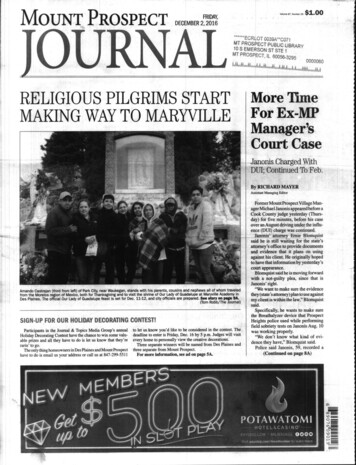
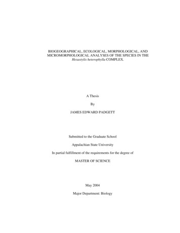
5When the two remaining roots were plotted as a function of temperature,one root increased with temperature and the other decreased. In Newtonianliquids, the viscosity decreases logarithmically as the temperature isincreased, therefore, the root that increased with temperature was discardedand the kinematic viscosity was calculated using the remaining root. Theabsolute viscosity was then calculated from the kinematic viscosity and thedensity, p, as follows:PIII. pv(23)EXPERIMENTALThe oscillating cup viscometer as shown in Fig. 1 consists of a closedcup suspended from a tungsten wire. The cup (Fig. 2) is a tungsten crucible25.48 mm in diameter and 50.8 mm high. In the center of the bottom is ablackbody cavity 0.508 mm in diameter and 3.05 mm deep. The filling neck isapproximately 76.2 mm long by 7.49 mm ID. All wall thicknesses are 1.02 mm.The crucible is a one-piece unit commercially fabricated by chemical vapordeposition. After the crucible is filled, a solid tungsten plug is slip-fittedinto the filling neck and electron-beam-welded in place.The sealed crucible is attached to a cylindrical block (an "inertiablock") by means of a tantalum connecting rod. The inertia block is designedto give the oscillating system a reasonable rate of attenuation and providesupport for the additional inertia blocks used to measure the moment of inertia.Above the inertia block is attached a rod containing a reflecting mirror, whichis attached to the suspension wire by means of a small chuck. The tungstensuspension wire is 0.178 mm in diameter by 0.31 m long. The upper end of thewire is attached by a chuck to a rotational mechanical feedthrough. Rotationof the feedthrough is used to start oscillation of the suspended system.The combined parameters of wire material and diameter, and the inertiablock mass and diameter significantly affect the rate of attenuation of thesuspended system.If the rate is too high, flow within the crucible isturbulent and erroneous measurements may result; if rate is too low, anunreasonably long time may be required to make a measurement.The entire assembly was mounted in a high vacuum, ion-pumped, tungstenmesh furnace (Varian VF-100). The hot zone of the furnace consists of a splittungsten-mesh heating element with power provided by a stepdown transformer.A front-opening door allows complete access to the work zone of the furnace.Temperature control was achieved by monitoring the power input through afast response thermal-watt converter and controlling the power input,either manually or automatically.A vacuum of 3 x 10⁻⁷ Pa was achieved through a combination of mechanical,titanium-sublimation, and ion pumps. Before measurements were performed,the mechanical pump was turned off. The ion pump and sublimation pump thenprovided a vibration-free pumping system for the furnace.The logarithmic decrement of the oscillating cup is measured by shininga narrow beam of light from a small helium-neon laser through a window ontothe reflecting mirror, as shown in Fig. 3.The reflected light beam strikes
6CHUCKSUSPENSIONWIREWINDOWREFLECTORINERTIA BL OCKHEATEDZONEFig. 1.CRUCIBLEOscillating Cup ViscometerANL Neg. No. 308-77-210a photodetector each time the suspension system passes a precisely known pointslightly offset from center. The time interval for each successive swingin the same direction is measured with a Monsanto 8510 counter/timer and isrecorded on an attached printer. The logarithmic decrement, 6, iscalculated from the relationshipcosdN InN(ot) 0cosTJi
77.49 mm I. D.- 1.02 mm WALL50.8mm,25.48mm0.508 mm 1.0.3.05 mm DEEPFig. 2.Tungsten Viscometer CupANL Neg. No. 308-77-636PHOTO DETECTORTIMERPRINTERMIRRORFig. 3.LASigSchematic of Electronic Equipmentfor Viscosity MeasurementsANL Neg. No. 308-77-211
8where(At)N-the time interval of the Nth swing(A)0 the time interval of the initial swingN-number of swings measuredT - period of the oscillationsWhen measurements are made, the logarithmic decrement is calculated foreach set of 10 successive swings. Usually, 10-20 logarithmic decrementmeasurements are made dt a given temperature and are then averaged to obtaina final value.The temperature of the crucible was measured using a Leeds and NorthrupModel 8634-C disappearing-filament optical pyrometer. The optical pyrometerwas sighted through a prism and window located at the bottom of the furnaceonto the blackbody cavity in the sample crucible. A magnetic shutter protectedthe window from exposure to the furnace environment except while temperaturemeasurements were being made. The optical pyrometer, window, and prismwere calibrated with strip lamps which had been calibrated by the NationalPhysical Laboratory (Teddington, England).The material used in these measurements was alumina powder of 99.997purity obtained from Alfa Division, Ventron Corporation. The crucible wasfilled incrementally with a known amount of alumina by successive loading andmelting steps. The tungsten plug was then electron-beam-welded in placeunder vacuum to complete preparations for the measurements.Spectrochemical analysis of the alumina before and after thesemer.surements showed no significant changes in composition. The tungstenconcentration was -0.012 before and %0.012 after the measurements.Theseresults indicate that essentially no interaction occurred between the aluminaand the crucible.IV.RESULTS ANDDISCUSSIONTo calculate viscosity from the logarithmic decrement, it is firstnecessary to measure the inherent logarithmic decrement and the moment oinertia. The Inherent logarithmic decrement is due primarily to the restoringforce caused by the internal friction within the twisting suspension wire.Before measurements were made on molten alumina, several measurements of thelogarithmic decrement were made just below the melting point of alumina. Theaverage of these measurements vas 0.001577 and this was subtracted from thelogarithmic decrements measured for molten alumina.Using the fact that the period varies inversely with the square root ofthe moment of inertia, the moment of inertia for the whole system wasdetermined by measuring the period of the system and then adding severalblocks with precisely known moments of inertia. From these measurements, themoment of inertia was found to be 2.4001 x 10'4 kg-m 2
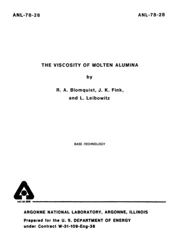
In order to test opeurit ion ott the system, visc o si tv nvastirements weremade on water at roanm temperature.Results agreed within an average of2% with literature valties.This agreement was constidered satisfactory forour purposes.The viscosityot molten alumina was measured in the temperature range from2394 to 2742 K.The results of the viscosity measurements are given in Table1. At each temperature the corrected radius of the crucible was calculatedusing the thermal expansion data ot Toiloukian."The density of alumina usedto calculate viscosities is the average of the densit ies measured by Bates 6and EIlyut in,7 whose values agreed within 1.5%.Over the temperature range ofour experiments, the viscosity, 'i, may be represented by the equation:1ni-n114488.27114pasica 1 seconds * and the temperature T 1-i in kelvins.Thethe standard error of this fit is about 4%. Our viscosity dataare presented graphical ly in Fi . 4.Also presented in Fig. 4 for comparisonare the viscosity data of Bates' ilnd f E:lyut in. 7 Our data agree well withthose of Elyut in but dii fer signif ie'an t ly front those of Bates. The cause ofthis discrepant y is not known at prese nt. The activation energy for viscousf low ca lcu hated from our data is 95 k.l /mol .This value is in fair agreementwith the value of 126 k.l/mol reported by F:lytt in.7where ri IsIstimaite ofinTab Itv1.Measurementsof' Viscosity of AluminaMass it Alumni a:Moment ',I Inerat l:Crucible Had IusTemp.,K24582 5092412255826h1274226182398245324202394I Pa-. " 103 cp.,/.10') g2.4001 x 'nl' kg-m'12.74 mmietsit y,10' kg/mlper iod,I.ogar thmicDec reinen tVisCosity,ri2.852.7915.29715. 10115.30515.282I5. ,10.01 170.0 PIa-
10iiiiiIii0.10.08aI0ii0000.06OO0O0.04UVa S ATESELYUT IN-0.02o THIS WO RK0.01I3000III2800IIIIII24002600 2500I2300TEMPERATURE, KFig. 4.Viscosity of Molten AluminaAN. Neg. No. 308-77-421Several investigators8- 1 2 have suggested empirical relationships whichcan be used to estimate the viscosity of molten materials near their meltingpoints. These methods have been applied to molten alumina, and the resultsare summarized in Table 2. The wide range of estimates given in the tableindicates the difficulty that can be encountered in accurately estimatingthe viscosity of a material such as molten alumina. Most empirical methodsof estimation are based on materials such as metals, which have less complexmolecul.r structures than alumina, and it is probably for this reason thatthese estimation methods fail when applied to molten alumina.Table 2.Viscosity of Molten Alumina Nearthe Melting Point: Experimentaland Calculated ValuedViscosity,Pa-sBird, Stewart, and Lightfoot (Ref. 8)0.0056aGlasstone et al. (Ref. 9)0.343aPartington (Ref. 10)0.00237aKumar et al. (Ref. 11)0.003bSokolov (Ref. 12)9.43bExperimental, this work0.035aCalculated by us using the method described in thereference given.bEstimated value from the reference given.
11V.SUMMARYThe viscosity of molten alumina has been measured using an -scillatingcup viscometer.The viscosity, n, is represented by the equationIn r,11448T8.2734for the the temperature range from 2394 to 2742 K.for viscuus flow is 95 kJ/mol.The activation energyThe experimental measurements on molten alumina have demonstratedthe usefulness of the oscillating cup method for measuring the viscosity ofmaterials at high temperatures.
12REFERENCES1.J. S. Finucane and D. R. Olander, High Temp. Sci. 1, 266-480 (1969).2.L. J. Wittenberg, D. Ofte, and C. F. Curtiss, J. Chem. Phys. 48,3253-3260 (1968).3.R. Roscoe, Phys. Soc. of London 72, 576-584 (1958).4.R. B. Bird, W. E. Stewart, and E. N. Lightfoot, Transport Phenomena,John Wiley and Sons, Inc., New York, pp. 140-142 (1960).5.Y. S. Touloukian, R. K. Kirby, R. E. Taylor, and P. D. Desai, Thermo-physical Properties of Matter, IFI/Plenum Press, New York-Washington,Vol. 2, p. 354 (1975).6.J. L. Bates, C. E. McNeilly, and J. J. Rasmussen, Properties of MoltenCeramics, Vol. 5, Ceramics in Severe Environments, Material ScienceResearch, W. W. Kriegel and H. Palmour III, Eds., Plenum Press, New York,pp. 11-26 (1971).7.V. P. Elyutin, B. C. Mitin, and Yu. A. Nagibin, Fiz. AerodispersnvkhSist., No. 7, pp. 104-9 (1972).8.R. B. Bird, W. E. Stewart, and E. N. Lightfoot, Transport Phenomena,John Wiley and Sons. New York, p. 29 (1960).9.S. Glasstone, K. J. Laidler, and H. Eyring, The Theory of Rate Processes,McGraw-Hill Book Co., Inc., New York, p. 486 (1941).10.J. R. Partington, An Advanced Treatise on Physical Chemistry, Vol. 2,The Properties of Liquids, Longman, Green & Co., New York, p. 108 (1951).11.R. Kumar, L. Baker, Jr., and M. G. Chasanov, unpublished work (1974).12.0. K. Sokolov, Calculation of Viscosity in Molten Salts, NASA TT F-416(1966), translation of Raschet Vyazkosti Rasplavlennykh Soley,Izv. Vyssh. Uchebn. Zaved., Tsvetn. Metall. 5 (1), 89-93 (1962).
R. A. Blomquist, J. K. Fink, and L. Leibowitz ABSTRACT In the analysis of LMFBR core-containment and heat-removal problems associated with hypothetical core-disruptive accidents, viscosity data on molten ceramics are needed to help analyze the convective heat transfer and flow patterns within liquid pools.