Transcription
Documentation EtherCAT Library for LabVIEW 3This document describes the usage and installation of the “EtherCAT Library for LabVIEW“version 3.00.123456789General Information . 3System Requirements. 42.1Operating system . 42.2PC System . 42.3Network adapter . 42.4LabVIEW . 4Installation . 53.1LabVIEW Library . 53.2LabVIEW Examples . 53.3Tools and Documents . 53.4Network Card Driver. 6Basic Programming . 74.1System Driver . 74.2EtherCAT Master . 74.3Bus State . 94.4Reading And Writing Cyclic Process Data (PDO) . 104.5Buffered Reading Cyclic Process Data (PDO). 104.6Buffered Writing Cyclic Process Data (PDO). 114.7Topology And Slave Information . 124.8Object Dictionary . 134.9Reading and Writing Service Data Objects (SDO). 134.10 EtherCAT Master Events . 13Data Processing Functions. 145.1Limit Monitor. 145.2Bool Logic . 155.3PID Control Loop. 155.4Bit Copy . 165.5Analog Copy . 16ENI Files . 176.1Creation with LabVIEW. 176.2Creation with TwinCAT . 186.3Creation with EC Engineer . 19Licensing . 217.1Standard .Fehler! Textmarke nicht definiert.7.2USB Dongle . 22Getting Started . 23Troubleshooting . 24Documentation EtherCAT Library LabVIEW 3.00.docxpage 1 of 27
9.1Log Files . 249.2Administrator Rights. 249.3Real-Time Window . 259.4Windows requires a digitally signed driver . 259.5Windows not booting after installation real-time driver . 2610 Support . 27Documentation EtherCAT Library LabVIEW 3.00.docxpage 2 of 27
1 General InformationThe “EtherCAT Library for LabVIEW” allows direct data exchange with EtherCAT slaves. LabVIEW actsas an EtherCAT Master and controls the slaves in the EtherCAT topology. A Connection can be madewith a normal network adapter (NIC). The EtherCAT Master can be run with a real-time driver forcontrolling the NIC. This allows a deterministic bus rate of up to 10 kHz and the usage of DistributedClocks. As an alternative, the EtherCAT Master can also be run in Windows mode without real-timebehavior.The library provides a wide set of EtherCAT functionality like: Cyclic process data exchange CAN over EtherCAT (CoE) Servo Profile over EtherCAT (SoE) protocol Access to Slave EEPROM and Registers File Transfer over EtherCAT (FoE) mailbox protocol Synchronization with Distributed Clocks (DC) including Master Synchronization (DCM)Documentation EtherCAT Library LabVIEW 3.00.docxpage 3 of 27
2 System Requirements2.1 Operating systemThe library can be used on Windows 7, 8.1 and 10 with 32 and 64 bit.2.2 PC SystemIn real-time ModeThe real-time driver requires PC Systems with ACPI (Advanced Configuration and Power Interface) orAPIC (Advanced Programmable Interrupt Controller).In Windows ModeNo restrictions regarding PC hardware.2.3Network adapterIn real-time ModeEtherCAT protocol is run on a normal network adapter, which is controlled by a real-timeenvironment. This requires the installation of a real-time driver for the NIC and limits the supportednetwork adapters to chipsets from Intel and Realtek.In Windows ModeNo restrictions regarding Network adapter.2.4LabVIEWThe library can be used with LabVIEW 2013 to LabVIEW 2019 in 32 and 64 bit.Documentation EtherCAT Library LabVIEW 3.00.docxpage 4 of 27
3 Installation3.1LabVIEW LibraryThe installer installs files directly to the LabVIEW folder (.\program files\NationalInstruments\LabVIEW xx\.)The library is installed into the intr.lib folder in the subfolder " Ackermann Automation\EtherCATLibrary".The functions palette is installed under Instrument Drivers.3.2LabVIEW ExamplesThe examples are installed in the LabVIEW examples folder “.\Program Files\NationalInstruments\LabVIEW xx\examples\Ackermann Automation\EtherCAT Library “.3.3Tools and DocumentsAll further tools and documents can be found in:“.\ProgramData\Ackermann Automation\EtherCAT Library\3.x“Documentation EtherCAT Library LabVIEW 3.00.docxpage 5 of 27
3.4 Network Card DriverIn real-time ModeThis topic is covered in the document "Installation real-time Driver".In Windows ModeIn Windows mode the WinPcap or NPcap driver has to be installed. These drivers can be ation EtherCAT Library LabVIEW 3.00.docxpage 6 of 27
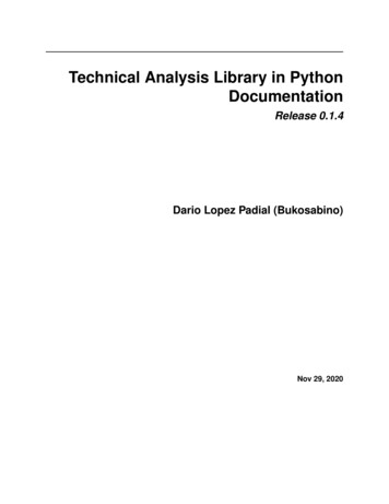
4Basic ProgrammingThis chapter describes the principals of programming with the library. The detailed VI informationcan be found in the help file.4.1System DriverThe function “Open System Driver” has to be called before all other function calls.This function prepares the real-time environment and checks the license activation status. If thelicense is not using a USB dongle, the license key has to be entered. If no dongle or valid license key isfound, the library is running in demo mode for 10 minutes.The driver has to be closed when finishing execution. This will shut down the resources of the realtime environment.Avoid stopping execution without using the Close System function call!4.2EtherCAT MasterAfter the system driver has been opened, the EtherCAT Master can be started. The EtherCAT Mastercan be run with the real-time Driver or in Windows mode. Which option is selected is determined bythe Open Master function. The Windows mode does not support the whole functionality of thelibrary due to the lack of deterministic timing behavior.In both cases an ENI file is required to run the master with cyclic process data. This XML file containsthe information about the whole EtherCAT system including the slave and process data description.The ENI file is described in the chapter "ENI Files".All actions that do not require Master state higher PreOp (CoE, memory access, bus scan, etc.) can bedone without an ENI file.Documentation EtherCAT Library LabVIEW 3.00.docxpage 7 of 27
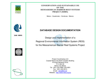
If no ENI file path is entered, a basic configuration is created by the master. In this configuration thephysical slave addresses start from 1. In common ENI configuration tools like TwinCAT or EC Engineerphysical slave addresses start from 1001.In real-time ModeOpening the EtherCAT Master requires the network adapter information and the CPU core selection.The network adapter (NIC) has to be selected. The network adapter has to be assigned to the realtime (see document "Installation real-time Driver"). There are 4 different types of network adapterclasses supported. Intel 100 and 1000 Mbit NICs and Realtek 100 and 1000 Mbit NICs. The type isidentified by the following 100"The processor parameter defines the CPU core usage of the real-time driver. The real-time driver canbe used in two different modes. In shared mode, Windows and the real-time driver share a CPU core.In exclusive mode, the real-time driver uses one CPU core exclusively. This core has to be taken fromWindows (see document " Installation real-time Driver ").On 64bit Systems, only exclusive mode is available!In Windows ModeOpening the EtherCAT Master only requires the network adapter information.The windows network adapter to be used has to be given a static IP address in the Windows networkconfiguration. This IP address is used to identify the network adapter.Documentation EtherCAT Library LabVIEW 3.00.docxpage 8 of 27
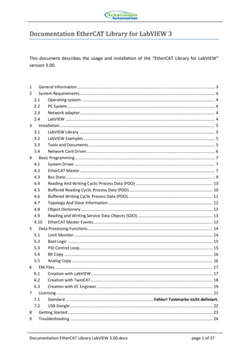
The bus cycle rate determines the rate in which the cyclic process data is sent. In Windows mode thisrate is limited to 1 kHz with non deterministic Windows timing. In real-time mode the bus cycle ratecan be up to 10 kHz.The function returns a task ref, which all other functions use as input.4.3Bus StateThe EtherCAT bus states "Init", "PreOp", "Boot", "SafeOp" and "Op" can be set with the function SetBus State. The state is set for the master which tries to set all connected slaves into this state. Cyclicprocess data exchange is executed in the states "SafeOp" and "Op". In "SafeOp" no outputs are set inthe slaves.Documentation EtherCAT Library LabVIEW 3.00.docxpage 9 of 27
The functions start and stop are shortcuts to "Op" and "Init" state.4.4Reading And Writing Cyclic Process Data (PDO)The cyclic process data is organized in an input data image and a output data image. These datasections contain all the input and output process data from the slaves in the topology. The singleframe read and write calls give access to these data sections.These functions give direct access and have no buffering. That means, if the bus cycle rate is fasterthan the LabVIEW loop, process data is lost.4.5Buffered Reading Cyclic Process Data (PDO)Only supported in realtime mode.With the buffered data exchange of cyclic process data, the cyclic bus rate can be greater than theLabVIEW loop to handle the process data. Data is transferred in packets. Input data can be acquiredwithout data loss.If cyclic process data is to be transferred in buffered mode, a buffer has to be created before. Thebuffer size is determined in count of frames. So for example a size of 1000 can hold data for 1000cycles. When running a cycle rate of 1 kHz, the buffer can hold data for 1 second. The input bufferalways uses the full input process data.The read function usees a 2D arrays for the data exchange. A row of the array is the data of onecycle.Documentation EtherCAT Library LabVIEW 3.00.docxpage 10 of 27
The input data contains the data of inputs and outputs of one process data cycle. A timestamp in µsof the time the telegra
Documentation EtherCAT Library LabVIEW 3.00.docx page 5 of 27 3 Installation 3.1 LabVIEW Library The installer installs files directly to the LabVIEW folder (.\program files\National Instruments\LabVIEW xx\.) The library is installed into the intr.lib folder in the subfolder "_Ackermann Automation\EtherCAT Library".