Transcription
https://www.halvorsen.blogLabVIEW LINX Arduinousing SPI and I2CHans-Petter Halvorsen
Table of Contents Introduction Arduino LabVIEW– LabVIEW LINX SPI and I2C Communication Protocols I2C– TC74 Temperature Sensor with I2C Interface– LabVIEW LINX Example SPI– DAC MCP4911 – Digital to Analog Converter with SPI Interface(Arduino has no Analog Out)– LabVIEW LINX Example
https://www.halvorsen.blogIntroductionHans-Petter HalvorsenTable of Contents
Contents This Tutorial shows how we can use Arduino in combination with the LabVIEWProgramming environmentArduino is a cheap open-source Microcontroller platform with Input/Outputpins that can be used for many purposes like reading Sensor data,Datalogging, Internet of Things Applications, etc.LabVIEW is a popular Graphical Programming EnvironmentLabVIEW LINX Toolkit is an add-on for LabVIEW which makes it possible toprogram the Arduino device using LabVIEWIf you don’t have “LabVIEW Professional” Software, you may use the“LabVIEW Community Edition”, which is free for non-commercial use. Youthen get a very low-cost DAQ/Datalogging System!In that way we can create Data Logging Applications, IoT Applications, etc.without the need of an expensive DAQ device or Software.In this Tutorial we will use the more advanced features and communicate withDigital Sensors, etc. using I2C and SPI Communication
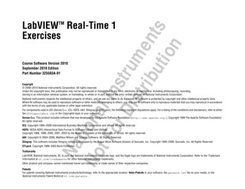
Arduino LabVIEW LINXBelow we see a typical Application where you can use an Arduino (Hardware)and LabVIEW/LabVIEW LINX (Software) to Log Data from a Sensor:PCArduino UNOLabVIEW SensorLabVIEW LINX ToolkitUSB cable Type A-BIn this Tutorial we will use the more advanced features andcommunicate with Digital Sensors, etc. using I2C and SPI Communication
HardwareArduinoBreadboardTC74Wires (Jumper Wires)TC74 Temperature Sensor with I2C 11MCP49Interface DAC MCP4911 with SPI Interface
https://www.halvorsen.blogArduinoHans-Petter HalvorsenTable of Contents
Arduino UNO Arduino is a Microcontroller Arduino is an open-source platformwith Input/Output Pins (DigitalIn/Out, Analog In and PWM) Price about 20 Arduino Starter Kit 40-80with Cables, Wires, Resistors, Sensors, etc.
Arduino I/O ChannelsDigital Inputs and Digital OutputsYou can choose from thecode if they are to beinputs or outputsThose marked with can alsobe used as "Analog Outputs",so-called PWM outputsAnalog Inputs
https://www.halvorsen.blogLabVIEWHans-Petter HalvorsenTable of Contents
LabVIEW LabVIEW is Graphical Software LabVIEW has powerful features forSimulation, Control and DAQapplicationsBasic LabVIEW Example:
https://www.halvorsen.blogLabVIEW LINXHans-Petter HalvorsenTable of Contents
LabVIEW LINX Toolkit The LabVIEW LINX Toolkit addssupport for Arduino, Raspberry Pi,and BeagleBone embeddedplatforms We will use Arduino UNO in thisTutorial
Installing LabVIEW LINX ToolkitUse VI Package MangerNote: Do not install this package if you are running LabVIEW 2020 Community Edition or later,as the Community Edition already includes the LabVIEW LINX Toolkit
LabVIEW LINX
LINX Firmware Wizard
LabVIEW Palette
https://www.halvorsen.blogSPI and I2CHans-Petter HalvorsenTable of Contents
SPI/I2C Digital Sensors typically use either the SPI orthe I2C communication protocol The Arduino UNO has built-in hardwaresupport for SPI and I2C communicationSPI 4-Wire Protocol SPI supports full-duplex. Data can besent and received at the same time Higher data transfer rate than I2C Complex wiring if more than oneSlaveI2C 2-Wire Protocol I2C supports only half-duplex. Datacannot be sent and received at thesame time Lower data transfer rate than SPI Multiple Slaves are easier
SPI/I2C in LabVIEW LINX
https://www.halvorsen.blogI2CInter-Integrated Circuit (I2C)Hans-Petter HalvorsenTable of Contents
I2C I2C is a multi-drop bus 2-Wire Protocol: SCL (Clock) SDA (Data) Multiple devices can be connected to the I2Cpins on the Arduino Each device has its own unique I2C address
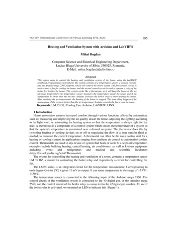
I2CMultiple devices can be connected to the I2C pins on the ArduinoMaster – Device that generates the clock and initiates communication with slavesSlave – Device that receives the clock and responds when addressed by the master.ArduinoI2C MasterSDASCLSDASCLI2C SlaveSDASCLI2C Slave ADC, DAC, Sensor, etc. with I2C Interface
I2C with ArduinoVDD – Power Supply InputGND – GroundSDA (A4 pin) - Serial Data – BidirectionalSCLK (A5 pin) - Serial Clock Input
https://www.halvorsen.blogTC74 TemperatureSensorHans-Petter HalvorsenTable of Contents
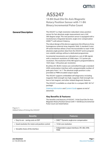
TC74 Temperature SensorSMBus/I2C InterfaceTC74A0-5.0VAT The TC74 acquires and convertstemperature information from its onboardsolid-state sensor with a resolution of 1 C. It stores the data in an internal registerwhich is then read through the serial port. The system interface is a slave SMBus/I2Cport, through which temperature data canbe read at any time. Device Address: 0x48Datasheet: 1462D.pdf
TC74 Example - WiringSDA - Serial Data – BidirectionalSCLK - Serial Clock InputVDD – Power Supply InputGND – GroundNC - Not in use (Not Connected)
LabVIEWBasic Example:
Slave AddressRight-click andSelect PropertiesThe TC74 Slave address isa Hexadecimal Number
LabVIEWContinuous Reading Example:
https://www.halvorsen.blogSPISerial Peripheral Interface (SPI)Hans-Petter HalvorsenTable of Contents
SPI Serial Peripheral Interface (SPI) 4–Wire Protocol (SCLK, CE, MOSI, MISO) SPI is an interface to communicate withdifferent types of electronic componentslike Sensors, Analog to Digital Converts(ADC), etc. that supports the SPI interface Thousands of different Components andSensors supports the SPI /hardware/raspberrypi/spi/
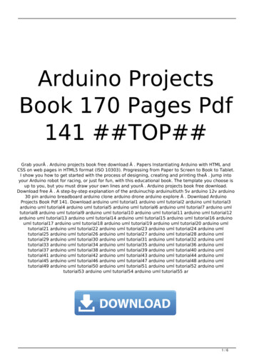
SPISPI devices communicate in full duplex mode using a master-slave architecture with asingle masterSPI ADC, SPI Sensor, etc.ArduinoSPI MasterSCLKMOSIMISOCESCLKMOSIMISOCESPI SlaveThe SPI bus specifies four logic signals: SCLK: Serial Clock (output from master) MOSI: Master Out Slave In (data output from master) MISO: Master In Slave Out (data output from slave) CE (often also called SS - Slave Select): Chip Select (often active low, output from master)
SPI with Arduino SCLK: Serial Clock (output from master) MISO: Master In Slave Out (data output fromslave) MOSI: Master Out Slave In (data output frommaster) CE (often also called SS - Slave Select): ChipSelect (often active low, output from master)
https://www.halvorsen.blogDAC - MCP4911DAC – Digital to Analog ConverterHans-Petter HalvorsenTable of Contents
DAC – MCP4911 DAC – Digital to Analog Converter Arduino UNO has no real Analog Out Channel –only Digital PWM channels We can use an external DAC in order to provide areal Analog Out MCP4911 is a single channel, 10-bit DAC with anexternal voltage reference and SPI interface
MCP49xxMCP49xx is a family of DAC ICs: MCP4901: 8-Bit Voltage Output DAC MCP4911: 10-Bit Voltage Output DAC MCP4921: 12-Bit Voltage Output DACThe different MCP49xx DACs work in the samemanner, the only difference is the resolution (8, 10,or 12 resolution)Datasheet: https://www.microchip.com/en-us/product/MCP4911
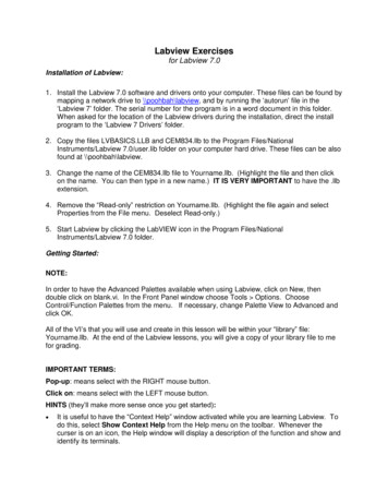
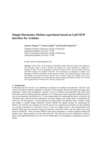
MCP4911 - Arduino WiringD13 (SCLK)𝐶𝑆𝑆𝐶𝐾D11 (MOSI)𝑆𝐷𝐼8 7 6 5D10 (SS)MCP4911𝑉!!1 2 3 45V𝑉"# 𝑉%%Analog Out (To Multimeter)𝑉&'(5V𝐿𝐷𝐴𝐶GNDGND
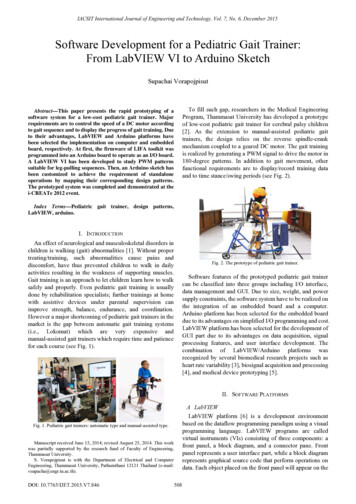
Test SetupMultimeterArduino UNOPCIn the LabVIEW Application 3V is writtento the MCP4911 DAC.Then we can use a Multimeter to see ifeverything works as expectedBreadboard withMCP4911 DA and somewires to the Arduino
MCP4911 – Write DataWrite Command 1D010-bit data2)* 1024 DAC Levels0𝑉 5𝑉 0 1023Datasheet: 0
SPI Write in LabVIEW LINX
MCP4911 – Write Data Examples0V DAC Value 010-bit data15141312111000110098070602)* 1024 DAC Levels504030202000000𝑉 5𝑉 0 102312288Need to Write Word 12288 to the MCP4911 Write Register divided into 2 ote! Word – 16Bits and Byte – 8 Bits
MCP4911 – Write Data Examples2.5V DAC Value 51210-bit data151413121110001110980702)* 1024 DAC Levels605040302020000512143360𝑉 5𝑉 0 1023Need to Write Word 14336 to the MCP4911 Write Register divided into 2 ote! Word – 16Bits and Byte – 8 Bits
MCP4911 – Write Data Examples5V DAC Value 102310-bit data15141312111000111198171612)* 1024 DAC Levels514131212100010230𝑉 5𝑉 0 102316380Need to Write Word 16380 to the MCP4911 Write Register divided into 2 252Note! Word – 16Bits and Byte – 8 Bits
Split Word into 2 Bytes in 00252Note! Word – 16Bbits and Byte – 8 Bits
LabVIEW
Convert from Voltage to Byte Array
Convert from Voltage to Byte Array
LabVIEWContinuous Writing Example:
https://www.halvorsen.blogCombined SystemTC74 MCP4911I2CSPIHans-Petter HalvorsenTable of Contents
TC74 (I2C) MCP4911 (SPI)Here is a basic example presentedwhere reading TC74 TemperatureData is combined with writingvalues to the MCP4911 DAC.It can easily be extended with, e.g.,a PID Control System
TC74 (I2C) MCP4911 (SPI)
TC74 (I2C) MCP4911 (SPI)
TC74 (I2C) MCP4911 (SPI)
TC74 (I2C) MCP4911 (SPI)
Summary TC74 Temperature Sensor with I2C Interface DAC MCP4911 – Digital to Analog Converter with SPI Interface Arduino is a cheap open-source Microcontroller platform withInput/Output pins that can be used for many purposes likereading Sensor data, Datalogging, Internet of ThingsApplications, etc. Arduino and LabVIEW/LabVIEW LINX is a powerfulcombination If you don’t have “LabVIEW Professional” Software, you mayuse the “LabVIEW Community Edition”, which is free for noncommercial use. You then get a very low-cost DAQ/Datalogging System!Table of Contents
Hans-Petter HalvorsenUniversity of South-Eastern Norwaywww.usn.noE-mail: hans.p.halvorsen@usn.noWeb: https://www.halvorsen.blog
LabVIEWis a popular Graphical Programming Environment LabVIEW LINX Toolkit is an add-on for LabVIEW which makes it possible to program the Arduino device using LabVIEW If you don't have "LabVIEW Professional" Software, you may use the "LabVIEW Community Edition", which is free for non-commercial use. You then get a very .