Transcription
Call 1(800)985-6929 for Salesdeltaacdrives.comsales@deltaacdrives.comCall 1(800)985-6929 for Salesdeltaacdrives.comsales@deltaacdrives.com
Call 1(800)985-6929 for Salesdeltaacdrives.comsales@deltaacdrives.comCall 1(800)985-6929 for Salesdeltaacdrives.comsales@deltaacdrives.com
Call 1(800)985-6929 for Salesdeltaacdrives.comsales@deltaacdrives.comCall 1(800)985-6929 for Salesdeltaacdrives.comsales@deltaacdrives.com
Call 1(800)985-6929 for ceThank you for choosing DELTA’s high-performance VFD-M Series. The VFD-M Series ismanufactured with high-quality components and materials and incorporate the latest microprocessortechnology available.This manual is to be used for the installation, parameter setting, troubleshooting, and dailymaintenance of the AC motor drive. To guarantee safe operation of the equipment, read the followingsafety guidelines before connecting power to the AC motor drive. Keep this operating manual athand and distribute to all users for reference.To ensure the safety of operators and equipment, only qualified personnel familiar with AC motordrive are to do installation, start-up and maintenance. Always read this manual thoroughly beforeusing VFD-M series AC Motor Drive, especially the WARNING, DANGER and CAUTION notes.Failure to comply may result in personal injury and equipment damage. If you have any questions,please contact your dealer.PLEASE READ PRIOR TO INSTALLATION FOR SAFETY.DANGER!1.2.AC input power must be disconnected before any wiring to the AC motor drive is made.A charge may still remain in the DC-link capacitors with hazardous voltages, even if the powerhas been turned off. To prevent personal injury, please ensure that power has turned off beforeopening the AC motor drive and wait ten minutes for the capacitors to discharge to safe voltagelevels.3.Never reassemble internal components or wiring.4.The AC motor drive may be destroyed beyond repair if incorrect cables are connected to theinput/output terminals. Never connect the AC motor drive output terminals U/T1, V/T2, andW/T3 directly to the AC mains circuit power supply.5.Ground the VFD-M using the ground terminal. The grounding method must comply with thelaws of the country where the AC motor drive is to be installed. Refer to the Basic WiringDiagram.6.VFD-M series is used only to control variable speed of 3-phase induction motors, NOT for 1phase motors or other purpose.7.VFD-M series shall NOT be used for life support equipment or any life safety situation.Call 1(800)985-6929 for Salesdeltaacdrives.comsales@deltaacdrives.com
Call 1(800)985-6929 for NG!1.DO NOT use Hi-pot test for internal components. The semi-conductor used in AC motor driveeasily damage by high-voltage.2.There are highly sensitive MOS components on the printed circuit boards. These componentsare especially sensitive to static electricity. To prevent damage to these components, do nottouch these components or the circuit boards with metal objects or your bare hands.3.Only qualified persons are allowed to install, wire and maintain AC motor drives.CAUTION!1.Some parameters settings can cause the motor to run immediately after applying power.2.DO NOT install the AC motor drive in a place subjected to high temperature, direct sunlight,high humidity, excessive vibration, corrosive gases or liquids, or airborne dust or metallicparticles.3.Only use AC motor drives within specification. Failure to comply may result in fire, explosion orelectric shock.4.To prevent personal injury, please keep children and unqualified people away from theequipment.5.When the motor cable between AC motor drive and motor is too long, the layer insulation of themotor may be damaged. Please use a frequency inverter duty motor or add an AC outputreactor to prevent damage to the motor. Refer to appendix B Reactor for details.6.The rated voltage for AC motor drive must be 240V for 230V models ( 120V for 115V models; 480V for 460V models; 600V for 575V models) and the mains supply current capacity mustbe 5000A RMS.Call 1(800)985-6929 for Salesdeltaacdrives.comsales@deltaacdrives.com
Call 1(800)985-6929 for Salesdeltaacdrives.comsales@deltaacdrives.comTable of ContentsPreface . iTable of Contents . iiiChapter 1 Introduction . 1-11.1 Receiving and Inspection.1-21.1.1 Nameplate Information. 1-21.1.2 Model Explanation . 1-21.1.3 Series Number Explanation . 1-21.1.4 External Parts and Labels . 1-31.1.5 Remove Instructions . 1-4Remove Keypad. 1-4Remove Front Cover. 1-41.2 Preparation for Installation and Wiring.1-51.2.1 Ambient Conditions. 1-51.2.2 Minimum Mounting Clearances. 1-51.3 Dimensions .1-7Chapter 2 Installation and Wiring . 2-12.1 Basic Wiring Diagram .2-22.2 External Wiring .2-52.3 Main Circuit.2-62.3.1 Main Circuit Connection. 2-6Call 1(800)985-6929 for Salesdeltaacdrives.comsales@deltaacdrives.com
Call 1(800)985-6929 for Salesdeltaacdrives.comsales@deltaacdrives.com2.3.2 Main Circuit Terminals. 2-82.4 Control Terminal Wiring (Factory Settings) . 2-9Chapter 3 Keypad and Start Up .3-13.1 Keypad. 3-13.1.1 Description of the Digital Keypad . 3-13.1.2 How to Operate the Digital Keypad LC-M02E . 3-23.1.3 LC-M02E . 3-33.2 Operation Method . 3-53.3 Trial Run . 3-5Chapter 4 Parameters.4-14.1 Summary of Parameter Settings . 4-24.2 Parameter Settings for Applications . 4-144.3 Description of Parameter Settings. 4-20Chapter 5 Troubleshooting .5-15.1 Over Current (OC). 5-15.2 Ground Fault . 5-25.3 Over Voltage (OV). 5-25.4 Low Voltage (Lv) . 5-35.5 Over Heat (OH1) . 5-45.6 Overload . 5-45.7 Keypad Display is Abnormal . 5-55.8 Phase Loss (PHL) . 5-55.9 Motor cannot Run. 5-65.10 Motor Speed cannot be Changed . 5-75.11 Motor Stalls during Acceleration. 5-8Call 1(800)985-6929 for Salesdeltaacdrives.comsales@deltaacdrives.com
Call 1(800)985-6929 for Salesdeltaacdrives.comsales@deltaacdrives.com5.12 The Motor does not Run as Expected .5-85.13 Electromagnetic/Induction Noise .5-95.14 Environmental Condition.5-95.15 Affecting Other Machines .5-10Chapter 6 Fault Code Information and Maintenance. 6-16.1 Fault Code Information .6-16.1.1 Common Problems and Solutions. 6-16.1.2 Reset . 6-56.2 Maintenance and Inspections .6-5Appendix A Specifications. A-1Appendix B Accessories. B-1B.1 All Brake Resistors & Brake Units Used in AC Motor Drives . B-1B.1.1 Dimensions and Weights for Brake Resistors& Brake Units. B-3B.2 Non-fuse Circuit Breaker Chart . B-5B.3 Fuse Specification Chart . B-6B.4 AC Reactor. B-7B.4.1 AC Input Reactor Recommended Value. B-7B.4.2 AC Output Reactor Recommended Value. B-7B.4.3 Applications . B-8B.5 Zero Phase Reactor (RF220X00A) . B-10B.6 Remote Controller RC-01 . B-11B.7 PU06 . B-12B.7.1 Description of the Digital Keypad VFD-PU06 . B-12B.7.2 Explanation of Display Message. B-12Call 1(800)985-6929 for Salesdeltaacdrives.comsales@deltaacdrives.com
Call 1(800)985-6929 for Salesdeltaacdrives.comsales@deltaacdrives.comB.7.3 Operation Flow Chart.B-13B.8 AMD - EMI Filter Cross Reference . B-14B.8.1 Dimensions .B-17B.9 Din Rail . B-19B.9.1 Din Rail-DR01 Adapter .B-19B.9.2 Din Rail-DR02 Adapter .B-20Appendix C How to Select the Right AC Motor Drive . C-1C.1 Capacity Formulas.C-2C.2 General Precaution.C-4C.3 How to Choose a Suitable Motor .C-5Call 1(800)985-6929 for Salesdeltaacdrives.comsales@deltaacdrives.com
Call 1(800)985-6929 for er 1 IntroductionThe AC motor drive should be kept in the shipping carton or crate before installation. In order toretain the warranty coverage, the AC motor drive should be stored properly when it is not to be usedfor an extended period of time. Storage conditions are:CAUTION!1.Store in a clean and dry location free from direct sunlight or corrosive fumes.2.Store within an ambient temperature range of -20 C to 60 C.3.Store within a relative humidity range of 0% to 90% and non-condensing environment.4.Store within an air pressure range of 86 kPA to 106kPA.5.DO NOT place on the ground directly. It should be stored properly. Moreover, if the surroundingenvironment is humid, you should put exsiccator in the package.6.DO NOT store in an area with rapid changes in temperature. It may cause condensation andfrost.7.If the AC motor drive is stored for more than 3 months, the temperature should not be higherthan 30 C. Storage longer than one year is not recommended, it could result in the degradationof the electrolytic capacitors.8.When the AC motor drive is not used for longer time after installation on building sites or placeswith humidity and dust, it’s best to move the AC motor drive to an environment as stated above.Revision May 2008, ME14, SW V3.04Call 1(800)985-6929 for Sales1-1deltaacdrives.comsales@deltaacdrives.com
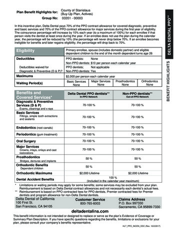
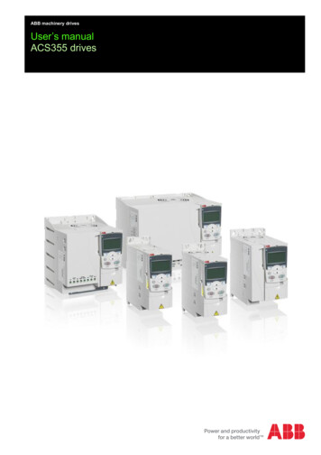
Call 1(800)985-6929 for er 1 Introduction 1.1 Receiving and InspectionThis VFD-M AC motor drive has gone through rigorous quality control tests at the factory beforeshipment. After receiving the AC motor drive, please check for the following: Check to make sure that the package includes an AC motor drive, the User Manual/Quick Start Inspect the unit to assure it was not damaged during shipment. Make sure that the part number indicated on the nameplate corresponds with the part numberand CD, and rubber bushings.of your order.1.1.1 Nameplate InformationExample of 1HP 230V AC motor driveAC Dr ive ModelInput Spec.Output Spec.Output F requenc y RangeBar CodeSeri al NumberSoftwar e Vers ionMODE: V FD00 7M23AINPUT: 3P H 200 -2 40V 50/6 0Hz 6.0AOUTPUT : 3P H 0-240 V 5. 0A 1. 9kVA 1HPFreq. Ra nge :0. 1 4 00Hz007 M23A0 T0 0112 3003. 041.1.2 Model ExplanationVFD 007 M 23 AVersion TypeInput Voltage11:Single phase 115V 21:Single phase 230V23:Three phase 230V43:Three phase 460V53:Three phase 575VM SeriesApplicable motor capacity004: 0.5 HP(0.4kW) 037: 5 HP(3.7kW)055: 7.5HP(5.5kW)007: 1 HP(0.7kW)075: 10HP(7.5kW)022: 3 HP(2.2kW)Series Name1.1.3 Series Number ExplanationD007M23A0 T 5 01230V 3-phase 1HP(0.75kW)Production numberProduction weekProduction year 2005Production factory(Taoyuan)ModelIf the nameplate information does not correspond to your purchase order or if there areany problems, please contact your distributor.1-2Call 1(800)985-6929 for Salesdeltaacdrives.comRevision May 2008, ME14, SW V3.04sales@deltaacdrives.com
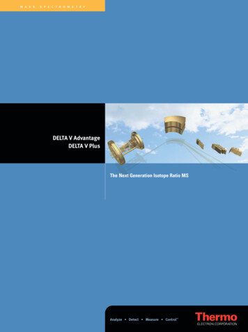
Call 1(800)985-6929 for er 1 Introduction 1.1.4 External Parts and LabelsRevision May 2008, ME14, SW V3.04Call 1(800)985-6929 for Salesdeltaacdrives.com1-3sales@deltaacdrives.com
Call 1(800)985-6929 for er 1 Introduction 1.1.5 Remove InstructionsRemove KeypadRemove Front CoverRST Side1-4Call 1(800)985-6929 for SalesUVW Sidedeltaacdrives.comRevision May 2008, ME14, SW V3.04sales@deltaacdrives.com
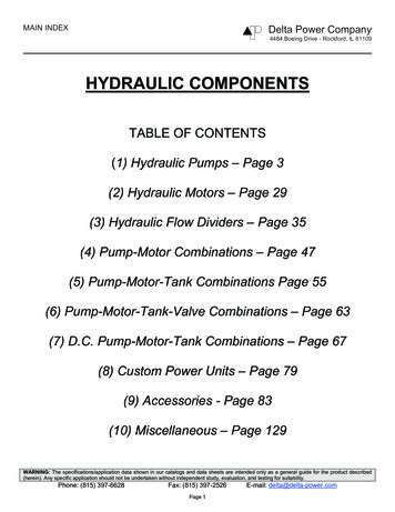
Call 1(800)985-6929 for er 1 Introduction 1.2 Preparation for Installation and Wiring1.2.1 Ambient ConditionsInstall the AC motor drive in an environment with the following conditions:-10 50 C (14 122 F) for UL & cULAir Temperature:-10 40 C (14 104 F) for 5.5kw models and aboveRelative Humidity:OperationAtmospherepressure:Installation SiteAltitude:86 106 kPa 1000mVibration: 20Hz: 9.80 m/s2 (1G) max20 50Hz: 5.88 m/s2 (0.6G) maxTemperature:-20 C 60 C (-4 F 140 F)Relative Humidity: 90%, no condensation allowedStorageTransportation Atmospherepressure:86 106 kPa 20Hz: 9.80 m/s2 (1G) max20 50Hz: 5.88 m/s2 (0.6G) maxVibration:PollutionDegree 90%, no condensation allowed2: good for a factory type environment.1.2.2 Minimum Mounting Clearances150mm50mm50mm150mmRevision May 2008, ME14, SW V3.04Call 1(800)985-6929 for Salesdeltaacdrives.comAir Flow1-5sales@deltaacdrives.com
Call 1(800)985-6929 for er 1 Introduction CAUTION!1.Operating, storing or transporting the AC motor drive outside these conditions may causedamage to the AC motor drive.2.Failure to observe these precautions may void the warranty!3.Mount the AC motor drive vertically on a flat vertical surface object by screws. Other directionsare not allowed.4.The AC motor drive will generate heat during operation. Allow sufficient space around the unitfor heat dissipation.5.The heat sink temperature may rise to 90 C when running. The material on which the AC motordrive is mounted must be noncombustible and be able to withstand this high temperature.6.When AC motor drive is installed in a confined space (e.g. cabinet), the surroundingtemperature must be within 10 40 C with good ventilation. DO NOT install the AC motor drivein a space with bad ventilation.7.Prevent fiber particles, scraps of paper, saw dust, metal particles, etc. from adhering to theheatsink.8.When installing multiple AC more drives in the same cabinet, they should be adjacent in a rowwith enough space in-between. When installing one AC motor drive below another one, use ametal separation between the AC motor drives to prevent mutual heating.Installation with Metal SeparationInstallation without Metal Separation1 50 mm1 50 mmB1 50 mmBAir Fl ow1 50 mm1 50 mm1 50 mmSide Vie w1-6Call 1(800)985-6929 for Salesdeltaacdrives.comRevision May 2008, ME14, SW V3.04sales@deltaacdrives.com
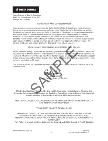
Call 1(800)985-6929 for er 1 Introduction 1.3 DimensionsDH2HD1H1WW1Unit: mm [inch]Model 1W1Unit: mm [inch]Model 2]Revision May 2008, ME14, SW V3.04Call 1(800)985-6929 for Salesdeltaacdrives.com1-7sales@deltaacdrives.com
Call 1(800)985-6929 for er 1 Introduction This page intentionally left blank1-8Call 1(800)985-6929 for Salesdeltaacdrives.comRevision May 2008, ME14, SW V3.04sales@deltaacdrives.com
Call 1(800)985-6929 for er 2 Installation and WiringAfter removing the front cover, check if the power and control terminals are clear. Be sure to observethe following precautions when wiring. General Wiring InformationApplicable CodesAll VFD-M series are Underwriters Laboratories, Inc. (UL) and Canadian UnderwritersLaboratories (cUL) listed, and therefore comply with the requirements of the National ElectricalCode (NEC) and the Canadian Electrical Code (CEC).Installation intended to meet the UL and cUL requirements must follow the instructions providedin “Wiring Notes” as a minimum standard. Follow all local codes that exceed UL and cULrequirements. Refer to the technical data label affixed to the AC motor drive and the motornameplate for electrical data.The "Line Fuse Specification" in Appendix B, lists the recommended fuse part number for eachVFD-M Series part number. These fuses (or equivalent) must be used on all installations wherecompliance with U.L. standards is a required.CAUTION!1.Make sure that power is only applied to the R/L1, S/L2, T/L3 terminals. Failure to comply mayresult in damage to the equipment. The voltage and current should lie within the range asindicated on the nameplate.2.All the units must be grounded directly to a common ground terminal to prevent lightning strikeor electric shock.3.Please make sure to fasten the screw of the main circuit terminals to prevent sparks which ismade by the loose screws due to vibration.4.Check following items after finishing the wiring:A. Are all connections correct?B. No loose wires?C. No short-circuits between terminals or to ground?Revision May 2008, ME14, SW V3.04Call 1(800)985-6929 for Salesdeltaacdrives.com2-1sales@deltaacdrives.com
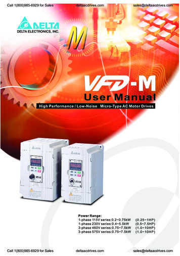
Call 1(800)985-6929 for er 2 Installation and Wiring DANGER!1.A charge may still remain in the DC bus capacitors with hazardous voltages even if the powerhas been turned off. To prevent personal injury, please ensure that the power is turned off andwait ten minutes for the capacitors to discharge to safe voltage levels before opening the ACmotor drive.2.Only qualified personnel familiar with AC motor drives is allowed to perform installation, wiringand commissioning.3.Make sure that the power is off before doing any wiring to prevent electric shock.2.1 Basic Wiring DiagramUsers must connect wires according to the following circuit diagram shown below.Brake Resistor (optional)Main Circuit PowerNFBR/L1S/L2T/L3Recommended Circuitwhen power supplyis turned OFF by afault outputR/L1 B1S/L2T/L3SAMCOFFONMCRBRCB2U/T1V/T2W/T3EThe spec. of main circuitterminal is M3.0RAFactory defaultForward/StopRBReverse/StopResetMulti-step 1Multi-step 2Multi-step 3Common signalMaster Frequency settingfactory default is VR which ison the digital keypad3Analog voltage0 10VDC VR 2VR:3K 5KΩM0AC MotorIM3 GroundingMulti-function indicationoutput contact120VAC/250VAC 5ARC24VDC less than 2.5AFactory default:indicates malfunctionMO1Multi-function Photocoupleroutput contact 48VDC 50mAM1M2M3Factory default: IndicatesMCM during operationVR(1KΩ)For adjustmentAFMM4M5GNDEPower for speed setting 10V 10mA(MAX)GNDERJ-11 -Analog outputDC 0 10VFactory default:output frequencyMain circuit (power)1:15Vterminals2:GNDControl circuit terminals3:SGAnalog currentACI4:SG GNDShielded leads5:ReservedE6:ReservedNOTE: Do not plug a Modem or telephone line to the RS-485 communicationport, permanent damage may result. Terminal 1& 2 are the powersources for the optional copy keypad and should not be used whileusing RS-485 communication.* If it is single phase model, please select any of the two input powerterminals in main circuit power.* Single phase model can be input 3-phase power.12-2Call 1(800)985-6929 for SalesAVIRS-485series interface6 1deltaacdrives.comRevision May 2008, ME14, SW V3.04sales@deltaacdrives.com
Call 1(800)985-6929 for er 2 Installation and Wiring CAUTION!1.2.The wiring of main circuit and control circuit should be separated to prevent erroneous actions.Please use shield wire for the control wiring and not to expose the peeled-off net in front of theterminal.3.Please use the shield wire or tube for the power wiring and ground the two ends of the shieldwire or tube.4.Damaged insulation of wiring may cause personal injury or damage to circuits/equipment if itcomes in contact with high voltage.5.The AC motor drive, motor and wiring may cause interference. To prevent the equipmentdamage, please take care of the erroneous actions of the surrounding sensors and theequipment.6.When the AC drive output terminals U/T1, V/T2, and W/T3 are connected to the motor terminalsU/T1, V/T2, and W/T3, respectively. To permanently reverse the direction of motor rotation,switch over any of the two motor leads.7.With long motor cables, high capacitive switching current peaks can cause over-current, highleakage current or lower current readout accuracy. To prevent this, the motor cable should beless than 20m for 3.7kW models and below. And the cable should be less than 50m for 5.5kWmodels and above. For longer motor cables use an AC output reactor.8.The AC motor drive, electric welding machine and the greater horsepower motor should begrounded separately.9.10.Use ground leads that comply with local regulations and keep them as short as possible.No brake resistor is built in the VFD-M series, it can install brake resistor for those occasionsthat use higher load inertia or frequent start/stop. Refer to Appendix B for details.11.Multiple VFD-M units can be installed in one location. All the units should be grounded directlyto a common ground terminal, as shown in the figure below. Ensure there are no groundloops.ExcellentRevision May 2008, ME14, SW V3.04Call 1(800)985-6929 for Salesdeltaacdrives.com2-3sales@deltaacdrives.com
Call 1(800)985-6929 for er 2 Installation and Wiring GoodNot allowed2-4Call 1(800)985-6929 for Salesdeltaacdrives.comRevision May 2008, ME14, SW V3.04sales@deltaacdrives.com
Call 1(800)985-6929 for er 2 Installation and Wiring 2.2 External WiringItemsPowersupplyPower agneticcontactor(Optional)Input ACLine ReactorInput ACLine ReactorZero-phaseReactor(Optional)EMI or(Ferrite actorOutput ACLine ReactorEMI filter(Optional)BrakeResistor(Optional)MotorOutput ACLine Reactor(Optional)Revision May 2008, ME14, SW V3.04Call 1(800)985-6929 for Salesdeltaacdrives.comExplanationsPlease follow the specific powersupply requirement shown inAPPENDIX A.There may be inrush current duringpower up. Please check the chart ofAPPENDIX B and select the correctfuse with rated current. NFB isoptional.Please do not use a Magneticcontactor as the I/O switch of the ACdrive, this will reduce the operatinglife cycle of the AC drive.Used to improve the input powerfactor, to reduce harmonics andprovide protection from AC linedisturbances. (Surge, switchingspike, power flick, etc.) AC linereactor should be installed when thepower supply capacity is 500kVAor phase lead reactor will beswitched. And the wiring distanceshould not exceed 10m. Please referto Appendix B for detail.Zero phase reactors are used toreduce radio noise especially whenaudio equipment installed near theinverter. Effective for noise reductionon both the input and output sides.Attenuation quality is good for a widerange from AM band to 10Mhz.Appendix B specifies zero phasereactors. (RF220X00A)To reduce electromagneticinterference. Please refer toAppendix B for detail.Used to reduce stopping time of themotor. Please refer to the chart onAppendix B for specific brakeresistors.Motor surge voltage amplitudesdepending on motor cable length. Forlong motor cable applications ( 20m),it is necessary to install on theinverter output side.2-5sales@deltaacdrives.com
Call 1(800)985-6929 for er 2 Installation and Wiring 2.3 Main Circuit2.3.1 Main Circuit ConnectionBrake Resistor(Optional)Non-fuse (T2)IM3 W(T3)ETerminal SymbolExplanation of Terminal FunctionR/L1, S/L2, T/L3AC line input terminals (three phase)U/T1, V/T2, W/T3Motor connectionsB1 – B2Connections for brake resistor (optional)Earth GroundCAUTION!Mains power terminals (R/L1, S/L2, T/L3) Connect these terminals (R/L1, S/L2, T/L3) via a non-fuse breaker or earth leakage breaker to3-phase AC power (some models to 1-phase AC power) for circuit protection. It is unnecessaryto consider phase-sequence. It is recommended to add a magnetic contactor (MC) in the power input wiring to cut off powerquickly and reduce malfunction when activating the protection function of AC motor drives. Bothends of the MC should have an R-C surge absorber. Please make sure to fasten the screw of the main circuit terminals to prevent sparks which ismade by the loose screws due to vibration.2-6Call 1(800)985-6929 for Salesdeltaacdrives.comRevision May 2008, ME14, SW V3.04sales@deltaacdrives.com
Call 1(800)985-6929 for er 2 Installation and Wiring Please use voltage and current within the regulation shown in Appendix A. When using a GFCI (Ground Fault Circuit Interrupter), select a current sensor with sensitivity of Do NOT run/stop AC motor drives by turning the power ON/OFF. Run/stop AC motor drives by200mA, and not less than 0.1-second detection time to avoid nuisance tripping.RUN/STOP command via control terminals or keypad. If you still need to run/stop AC drives byturning power ON/OFF, it is recommended to do so only ONCE per hour. Do NOT connect 3-phase models to a 1-phase power source.Output terminals for main circuit (U, V, W) When it needs to install the filter at the output side of terminals U/T1, V/T2, W/T3 on the ACmotor drive. Please use inductance filter. Do not use phase-compensation capacitors or L-C(Inductance-Capacitance) or R-C (Resistance-Capacitance), unless approved by Delta. DO NOT connect phase-compensation capacitors or surge absorbers at the output terminals of Use well-insulated motor, suitable for inverter operation.AC motor drives.Terminals [B1, B2] for connecting external brake unitBrake Resistor(optional)Refer to Appendix B for the use ofspecial brake resistorBR B2Connect a
5. Ground the VFD-M using the ground terminal. The grounding method must comply with the laws of the country where the AC motor drive is to be installed. Refer to the Basic Wiring Diagram. 6. VFD-M series is used only to control variable speed of 3-phase induction motors, NOT for 1-phase motors or other purpose. 7.