Transcription
United Launch Alliance Rideshare Capabilities forProviding Low-Cost Access to SpaceKeith KaruntzosUnited Launch AlliancePO Box 3788, MIS C4102Centennial, CO comAbstract-United Launch Alliance (ULA) has a long history ofproviding launch services to high-value payloads for a varietyof customers, including the US Department of Defense, theNational Reconnaissance Office, NASA, and commercialcustomers. These missions have deployed a wide variety ofcapabilities into Earth orbit and beyond, such as navigation,communication, R&D, observation, and science, all which haveprovided us with a tremendous amount of knowledge aboutEarth and our solar system. The majority of these spacecrafthas been launched as primary payloads, and used the fullcapability of the launch vehicle; yet there is a lower-costalternative for achieving similar mission objectives: rideshare.Rideshare is the approach of sharing available launch vehicleperformance and volume margins with two or more spacecraftthat would otherwise go underutilized by the spacecraftcommunity. This allows spacecraft customers the opportunityto get their spacecraft to orbit and beyond in an inexpensiveand reliable manner.This concept has been regularlydemonstrated since the 1960s, and these rideshare launcheshave proved that alternative ways to delivering importantpayloads to orbit in a cost-effective manner can be successfullyachieved.Rideshare missions will become even morecommonplace as newer launch service capabilities becomeavailable and the spacecraft customers choose to takeadvantage of them.The ULA family of launch vehicles - the Atlas V, the Delta II,and the Delta IV - all have rideshare capabilities that can beused by the community to launch payloads to orbit for a muchlower price than a dedicated single-manifest mission. Thesecapabilities support a wide range of spacecraft sizes, from thesmallest Cubesats, to the largest dual-manifest payloads. Thispresentation will provide a technical overview of current andfuture rideshare capabilities available, including Delta II P POD dispensers, the C-Adapter Platform (CAP), the Atlas VAft Bulkhead Carrier (ABC), the EELV Secondary PayloadAdapter (ESPA), the AQUILA, the eXternal Payload Carrier(XPC), and the Dual Spacecraft Systems (DSS-4 and DSS-5).Additionally, programmatic considerations for designing,manifesting, and integrating rideshare missions will bediscussed.T ABLE OF CONTENTS1. WHAT IS RIDESHARE?.2. RIDESHARE LAUNCH HISTORY 3. RIDESHARE CAPABILITY OVERVIEW 1234. MANIFESTING AND MISSION INTEGRATION OFRIDESHARE. . . . . . . . . . . . . . . . . . . . . . . . . . . . . .5. SUMMARY 978-1-4799-5380-6/151 31.00 2015 IEEE89REFERENCESBIOGRAPHY 9 91. VVHAT IS RIDESHARE?Since the dawn of the space age, spacecraft have oftenshared launch services with one another while beingdelivered into space. This approach has normally been doneto support spacecraft much smaller than the primary payloadit is launching with. By designing launch services in thismanner, spacecraft operators were able to deliver morepayloads to orbit for a fraction of the cost of a full-up launchservice.This method of launching multiple payloads into orbit on asingle launch vehicle is called rideshare. The use ofrideshare over the last 50 years has not always beenconsistent, but since the 1990s, with the development ofmore standardized mechanical interfaces for attaching thepayload to the launch vehicle, the number of ridesharemissions launched to orbit have increased. This continualimprovement in rideshare capabilities is allowing more andmore organizations to successfully design, produce, andlaunch payloads to orbit, increasing the amount ofoperational capability and scientific knowledge gained fromthese space-based payloads.Advantages of RideshareThe most obvious advantage to using the rideshare conceptfor launching payloads to orbit is the decreased cost to thecustomer. Instead of having to procure a dedicated launchvehicle to launch their single payload, the customer can getthe same delivery to orbit by launching as a secondary orco-manifest payload for a price much lower than a full-uplaunch service. The cost savings can then be applied to thepayload, or to other parts of the overall space mission'sarchitecture.In the case of dual manifest, the cost savings can beenormous. For example, for the GPS III program, bytransitioning from single-manifest to dual-manifest launchesfor the last 26 of 32 total spacecraft, the cost savings areanywhere from 750M to IB over the life of the program.Smaller constellations will not see as large a savings, buteven manifesting two spacecraft together onto a singlelaunch vehicle will provide almost 50M in savings.
Dual Manifest (DM)-Two primary payloads (of either adifferent design or the same design ) sharing a launch toorbit using dedicated dual manifest hardware.Rideshare DefinitionsThere are a numbercommunity to defineapproaches available.standardized across thethe tenns used byopportunities.of terms used within the spacethe various types of rideshareNot all tenns are completelyboard; however, the following areULA when discussing launch2. RIDESHARE LAUNCH HISTORYULA's launch systems have a long history of providingaccess to space to auxiliary, multi-manifest and dual manifest payloads through the Atlas and Delta families oflaunch vehicles. Since the 1960s, these rideshare launcheshave benefited customers of diverse mission areas includingcommercial communications, Earth science, militaryresearch and development and education.Auxiliary Payload (AP or APL)-A payload launched toorbit that is not a primary payload.Hosted I Piggyback Payload-An APL launched as part ofthe primary payload, and usually permanently attached.The approach of sharing available performance margin thatwould otherwise go unused by the primary payload hasprovided satellite customers the opportunity to get theirspacecraft to orbit in an inexpensive and reliable manner.ULA remains committed to the rideshare community bydeveloping new capabilities and solutions that allow for thelaunch of rideshare satellite customers for years to come. Alist of Atlas and Delta rideshare missions launched since2000 and scheduled out to 2016 are shown in Table 1.Secondary Payload (SP)-An APL launched as part of thelaunch vehicle, and usually designed to separate.Co-Manifest-General term for two or more primarypayloads manifested together.Multi-Manifest-Multiple spacecraft of the same designlaunched to orbit (This does not include multiple spacecraftlaunched as a single payload stack ).Table 1. ULA Rideshare History, SHAREHARDWARE USEDGlobalstar 7Delta II 74202/8/2000MultiPost DispenserEO-1ISAC-C/MuninDelta II 73201112112000Dual SecondaryDPAFJason-1ITIMEDDelta II 7920121712001DualDPAFIridium-12Delta II 7920211112002MultiPlatform DispenserICESatiCHIPSATDelta II 73201112/2003DualReduced-Height DPAFGPS IIR-8/XSS-10Delta II 7925112912003SecondaryDelta II Guidance SectionDelta IV Heavy DemolNanosat-2Delta IV Heavy12/20/2004PiggybackMission-unique bracketCALIPSOICloudSatDelta II 74204/28/2006DualDPAFSTP-1Atlas V 4013/8/2007SecondaryESPALRO/LCROSSAtlas V 4016118/2009SecondaryESPANPP/ELaNa IIIDelta II 792010/28/2011SecondaryDelta lI P-PODNROL-36/0UTSatAtlas V 4019113/2012SecondaryABCNROL-39/GEMSatAtlas V 50112/5/2013SecondaryABCAFSPC-41 ANGELSDelta IV M (4,2 )7/28/2014SecondaryESPASMAPIELaNa XDelta 11 73202015SecondaryDelta 11 P-PODAFSPC-5IULTRASatAtlas V 5012015SecondaryABCNROL-55IGRACEAtlas V 4012015SecondaryABC1CESat 11IEIaNaDelta 11 74202016SecondaryDelta 11 P-PODJPSS-1IELaNaDelta 11 79202016SecondaryDelta 11 P-POD2
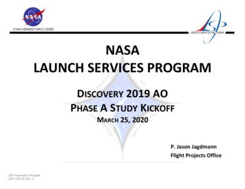
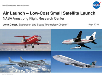
stages of development, but all are expected to be completedin order to support launch opportunities by the middle ofthis decade. An overview of the technical specifications anddevelopment status of each individual capability is shown inTable 2. Immediately following is a detailed technicaloverview of each one, and is provided to support futuremission planning for the entire rideshare community.3. RIDESHARE CAPABILITY OVERVIEWTo date, ULA has completed development or is continuingto develop a large number of rideshare capabilities andhardware, each with its own set of mass, volume, andinterface parameters that can support a multitude of payloadshapes and sizes. Each of the capabilities is at differentTable 2. ULA Rideshare Capability OverviewVolumePerPayloadCapabilityDelta II Second-StageMini-SkirtCAP (C-AdapterPlatform)ABC (AftBulkhead CarrierESPA (EELV SecondaryPayload Adapter)AQUILAP-PODOperational IXPC (eXternalPayload Carrier) II3 P-PODs8-inIn4 CAPsDevelopment Clampband15-inOperational1 ABCBolted15-inUp to 6 SCOperationalper ESPABoltedCDRUp to 3 SCVariable4/2012r.er AQUILAPDRVariable1 XPC1212010eDSS-4(Dual SpacecraftSystem, 4-m) 62-inBoltedCDR12120091.0 kg(2.2Ib)10 cm3(4 in3)45 kg(100 lb)80 kg(176Ib)181 kg(400Ib)1,000 kg(2,200Ib)1,810 kg(4,000Ib)23 cm x 31 cm x 33 cm(9 in x 12 in x 13 in)51 cm x 51 x 76 cm(20 in x 20 in x 30 in)61 cm x 71 cm x 96 cm(24 in x 28 in x 38 in142-cm dia. x 152 cm(56-in dia. x 60 in)21.2 m3(750 ft3)365-cm-dia. x 658 cm(144-in-dia. x 259 in)(3-plug)254-cm-dia. x 445 cm(100-in-dia. x 175 in)(3-plug)2,270 kg& (5,000Ib)1 DSS-4q:::9,000 kg (19,800Ib)eDSS-5(Dual SpacecraftSystem, 5-m) 62-inBoltedCDR12120141 DSS-55,440 kg& (12,000Ib)q:::9,000 kg (19,800Ib)II457-cm-dia. x 762 cm(180-in-dia. x 300 in)375-cm-dia. x 487 cm(148-in-dia. x 192 in)CubeSatslPoly Picosatellite Orbital Deployer (P-POD)Delta II Second-StageGuidance SectionCubeSats are the smallest spacecraft that can beaccommodated on ULA vehicles. The common dispenserfor this class of spacecraft is the Poly Picosatellite OrbitalDeployer (P-POD) developed by California PolytechnicUniversity, San Luis Obispo. An individual P-POD canaccommodate up to 3 CubeSats. ULA has pursued anumber of P-POD interface solutions for the Atlas and Deltavehicles. The first launch of P-PODs on a ULA vehicleoccurred on a Delta II in October 2011. Three P-PODswere attached around the circumference of the Delta IIsecond-stage, as shown in Figure 1.Mini-SkirtFigure 1. Delta II P-POD Interface3
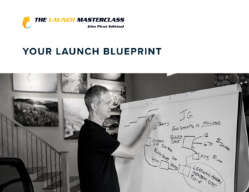
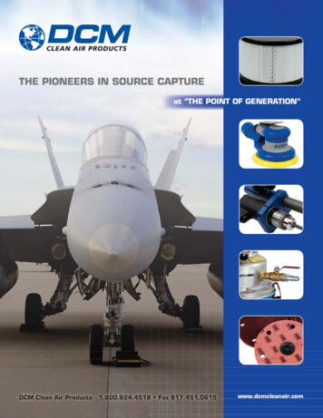
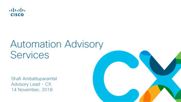
Another system for launching P-PODs is the Naval PostGraduate School (NPS) CubeSat Launcher (NPSCuL), asshown in Figure 2. The NPSCuL hosts eight P-PODs for atotal of 24 CubeSat slots. This launcher was first flown onan Atlas V in September 2012, with a second launch in2013, and two more scheduled in the coming years. TheNPSCuL is launched with an avionics box attached to itsside. This box receives the individual separation signalsfrom the Atlas Centaur second-stage Ordnance RemoteControl Assemblies (ORCA) and routes them to each P POD, allowing the CubeSats to be released on a pre determined schedule.C-AdapterPlatform (CAP)P-PODs (x 8)PayloadVolumeFigure 3. C-Adapter Platform (CAP)Aft Bulkhead Carrier (ABC)Avionics Box(Notional)The Aft Bulkhead Carrier (ABC) utilizes volume on theAtlas V Centaur aft bulkhead previously occupied by ahelium bottle that is no longer required. The ABC can carryan auxiliary payload with a mass of up to 80 kg (176 Ib).Located on the aft-end of the Centaur second-stage near theRLlO engine area, and using mounting attachment pointsthat use the existing tank doublers, the ABC provides ausable volume as shown in Figure 4. The ABC canaccommodate both separating and non-separating payloads,with a volume that is slightly larger for non-separatingpayloads. The ABC is large enough to accommodate a 15inch Motorized Lightband separation system.NPSCuLFigure 2. NPSCuL P-POD InterfaceC-Adapter Platform (CAP)The C-Adapter Platform (CAP) is a cantilevered platformthat is located within the payload fairing and is attached tothe side of a C-adapter. It can carry an auxiliary payloadwith a mass up to 45 kg (100 Ib).With additionalqualification, it may be possible to increase this mass limit.Figure 3 shows the basic configuration of a typical CAP.The number of CAPs and the positioning of the CAPsaround the circumference of the C-adapter are subject toavailable mission margins and mission requirements, but upto four CAPs could be accommodated on a single flight.The CAP can accommodate various deployment options,and it is large enough to accommodate an 8-inch MotorizedLightband, which can be mounted on either the base of theCAP or on the back wall. The CAP is compatible with boththe Atlas V and the Delta IV.Since the ABC is on the aft-end of the Centaur, it has theadvantage of not interfering with the primary payloadenvironment. It also has the ability to be deployed into low Earth orbit during the Centaur first-coast portion of themission, although the risk of doing so prior to primarypayload separation would need to be assessed.Theseparation plane of the ABC is tilted 17 degrees relative tothe longitudinal axis of the Centaur, providing clearance andno re-contact with the Centaur. To avoid contamination orplume impingement, the Centaur inhibits the normal settlingthrusters during the period of deployment.More information is available in the Aft Bulkhead CarrierAuxiliary Payload User's Guide, available for downloadfrom ULA [1].4
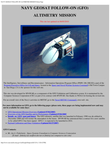
Atlas V CentaurSecond StageAft BulkheadCarrier (ABC)15-inch BoltedInterface (x 6)ESPAAtlas V CentaurForward Adapter (CFA)ABCPayloadVolumePayloadEnvelope (x 6)Figure 5. EELV Secondary Payload Adapter (ESPA)The ESPA can also be used as a separating spacecraft busstructure of the actual secondary payload. This was firstachieved on the NASA Lunar Crater Observation andSensing Satellite (LCROSS) mission (Figure 6), whichlaunched as a secondary payload on the LunarReconnaissance Orbiter (LRO) mission in 2009. After LROspacecraft separation, the ESPA-based LCROSS spacecraftstayed attached to the Centaur second stage, and shepardedit for three months, at which time it released the Centaurtowards the Moon to act as an impactor, LCROSS followingshortly afterward.Figure 4. Aft Bulkhead Carrier (ABC)EEL V Secondary Payload Adapter (ESPA)For missions with excess volume within the fairing, largerauxiliary payloads can be launched using the EELVSecondary Payload Adapter (ESPA), a 1.5-m-dia (62-indiameter), 61-cm-tall (24-in-tall) ring structure that cansupport up to six auxiliary payloads around itscircumference. Developed by Moog CSA Engineering, theESPA is mounted between the top of an Atlas V or Delta IVsecond-stage and the bottom of the primary payload'sspacecraft adapter, duplicating the EELV standard interfaceplane (SIP), and passing the electrical interfaces through tothe primary payload (Figure 5). The first launch of anESPA occurred on the Department of Defense Space TestProgram launch STP-l in March 2007.The auxiliary payload may be attached to the ESPA with aULA-supplied separation system or directly through acustomer-provided adapter. The ESPA ring includes six381-mm-dia (15-in-dia) bolt circle interfaces, with eachbeing able to accommodate a single auxiliary payload of upto 180 kg (400 Ib) in mass, and a volume of 61.0 cm x 71.1cm x 96.5 cm (24 in. x 28 in. x 38 in.). This total volumeincludes a 5.33 cm (2.l inch) separation system operationalenvelope.Only the separation system, its mountinghardware and its harness are permitted inside the separationsystem operational envelope. Detailed information on thestandard ESPA and its mission integration requirements aredocumented in the ESPA Rideshare User's Guide, availablefor download from ULA [2].Image courtesy of Northrop GrummanFigure 6.Lunar Crater Observation and SensingSatellite (LCROSS)5
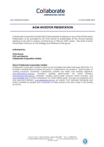
(SRB) (Figure 8), the XPC will attach to the first stage likeany other SRB, and ride with the first-stage booster upthrough booster separation. At this point in the ascent, theXPC would be flying at a velocity of Mach 14 at an altitudeof 700,000 ft. The XPC cover will jettison, allowing theinternal payloads to be released into a hypersonic suborbitaltrajectory.Other ESPA solutions, such as the 122-cm-tall (48-in-tall)ESPA Grande, with 60.9-cm-dia (24-in-dia) ports and anincreased capability of up to 318 kg (700 lb), can also beflown atop Atlas V and Delta IV launch vehicles.AQUILAThe AQUILA is a flexible stack of ring adapter segmentsthat provide an interior volume below the primary payload(Figure 7), and is designed to accommodate variousauxiliary payload types within its volume. The entire stackcan be configured to accommodate a variety of spacecraftvolumes, depending on the particular needs of the mission.It consists primarily of a mix of C-adapters of variousheights (l3, 24, or 25 inches). Additionally, a separationsystem can be added in order to separate the upper portionof the AQUILA from the lower portion. Also, an ESPAring can be added in place of a C-adapter in support ofmulti-manifest missions. The AQUILA has been developedby Adaptive Launch Solutions (ALS).The XPC will provide a 5 ft diameter and 750 cubic feet ofvolume. Technology development programs that wouldfmd the XPC beneficial may include Mars re-entry,Scramjet technology, or micro-gravity fluid dynamics andaerosols.Currently the XPC is under development by an industryteam led by Special Aerospace Services (SAS).XPCThe AQUILA uses an isogrid or aluminum flat-deck calledthe A-Deck at the bottom of the structure as the spacecraftinterface, which allows for the deployment of one ormultiple auxiliary payloads from within the internal volumeof the AQUILA. The internal envelope diameter of a C Adapter segment can accommodate auxiliary payloadsdiameters of up to approximately 56 inches. The heightavailable to the auxiliary payload can vary by the types andnumber of adapters used.Payload AQUILABoosterXPCCoverAtlas V CommonCore BoosterFigure 8. eXternal Payload CarrierDual Spacecraft System. 4-m (DSS-4)The Dual Spacecraft System, 4-m (DSS-4) is a capabilitydesigned and developed by ULA to enable the launch of twoindependent, small-to-medium class spacecraft within asingle Atlas V or Delta IV 4-m launch vehicle fairing, asshown in Figure 9. The DSS-4 makes extensive use ofexisting components with well-understood capabilities. Thelaunching of two similarly-sized dual spacecraft has alreadybeen demonstrated four times over the past decade on theDelta II Dual Payload Attach Fitting (DPAF). The launchprocessing and on-orbit concept of operations for the DSS-4is very similar to the DPAF.Atlas V Centaur ForwardAdapter (CFA)Figure 7. AQUILAeXternal Payload Carrier (XPC)An atypical approach to rideshare, the eXternal PayloadCarrier (XPC) is a payload carrier external to the Atlas Vfirst-stage. Appearing as an existing solid rocket boosterThe DSS-4 structure consists of two back-to-back CentaurForward Adapters (CFAs) with an optional addition of one,6
Dual Spacecraft System, 5-m (DSS-5)two, three, or four DSS-4 plug sections to provide flexibilityin the heights of the forward and aft spacecraft volumes.The CFA is an assembly of one cylindrical stub adapter anda conical adapter attached by a common ring. In the DSS-4application, the cylindrical parts of a lower, inverted CFAand an upper, non-inverted CFA mate together. This createsa canister which contains the lower spacecraft. The Atlas Vor Delta IV 4-m-diameter payload fairing completelyencloses the upper spacecraft and the DSS-4, while theDSS-4 itself encloses the lower spacecraft. The DSS-4supports the upper spacecraft and therefore all the lo dsfrom the upper spacecraft are carried by the DSS-4 dunngvehicle flight.Similar to the DSS-4, the DSS-5 is designed to dual-launchtwo medium-to-intermediate class payloads within an AtlasV or Delta IV 5-m payload fairing, as shown in Figure 10.The DSS-5 consists of a newly designed compositecylindrical canister and upper cone structure that enclosesthe lower payload and provides structural support for theupper payload. There is no change to the structural supportof the lower payload. The DSS-5 is being developed byULA and RUAG Space.The forward interface of the DSS-4 is the 62-inch StandardInterface Specification (SIS) payload interface, permittinguse of existing payload adapters. The aft interface attachesto the Atlas launch vehicle using a standard C-13 cylindricalpayload adapter. The DSS-4 can be flown within any AtlasV or Delta IV payload fairing as needed, based on thelengths of the two spacecraft and the Notional)AftPayload(Notional)DSS-4CanisterWith 3 sterSeparationPlaneFigure 10. Dual Spacecraft System, 5-m Fairing (DSS-5)A mission-unique adapter is used to attach the launchvehicle to the interface of the lower payload. The DSS-5provides support for the ULA-provided electrical harnessingto the upper payload, instrumentation, and upper payloadseparation system.AftPayload(Notional)The lower DSS-5 spacecraft volume is approximately 4-mdia. x 6.1 m (13.1-ft dia. x 20 ft), while the upper spacecraftvolume is slightly larger. The DSS-5 is designed to fly onboth the Atlas V and the Delta IV 5-m launch vehicles.Figure 9. Dual Spacecraft System, 4-m Fairing (DSS-4)7
spacecraft was unknown at that time. This allowed thelaunch service provider to appropriately plan for the missionahead of time. Once the standard NASA 30-month missionintegration effort began, the LCROSS payload had beenidentified, allowing both payloads to progress through theintegration cycle together, greatly reducing the amount ofadditional work to integrate the LCROSS rideshare. Thisapproach maximized mission capability and efficienciesbetween the primary payload and the rideshare payload.4. MANIFESTING AND MISSION INTEGRATION OFRIDESHAREDevelopment of mechanical interfaces for ridesharepayloads is only half the battle; mission integrationactivities on both the primary and rideshare spacecraft mustbe successfully completed to ensure that all payloads aresafely delivered to their orbit without damage to themselvesor the launch vehicle. Yet these activities cannot begin untila rideshare is manifested onto a launch service alongside aprimary payload. Rideshare missions can be manifestedonto a launch service in one of two ways. First, they can bemanifested as a rideshare onto an already-existing primarypayload mission.Second, they can be co-manifestedtogether with a companion rideshare payload early in thedevelopment process of both, allowing the payloads to bedesigned and integrated concurrently.Initial Assessment of Rideshare ManifestingFor either approach, there is a basic list of top-levelparameters that need to be assessed to determine if arideshare match is possible:Launch Date-Are the primary and rideshare payloadslaunching at the same time?Adding Rideshare Payloads to Existing MissionsOrbit-Are the primary and rideshare payloads going to thesame or similar orbits?The first approach is the historical way that the majority ofrideshare missions have been integrated and launched.However, this approach is more difficult to implement, asthe primary payload has already been matched up with aparticular launch vehicle configuration, including payloadfairing size and number of solid rocket motors. Dependingon the mass and volume of the rideshare payload, theseparameters might need to be changed to physicallyaccommodate the rideshare. If a change to the launchvehicle configuration is implemented, it could impact theschedule, as new hardware might need to be procured tomeet the new requirements. An impact to mission cost willalso occur, as the inclusion of a larger fairing or additionalsolid rocket motors will need to be paid for.Mass-Does the launch vehicle have enough mass marginto deliver all payloads to their respective orbits?Volume-Does the fairing volume provide enough room forall payloads?Schedule-Is there enough time to adequately integrate themission?Funding-Does the rideshare payload have enough budgetto support both early feasibility studies and missionintegration work?Once these parameters are assessed, and assuming a positiveresult, then the primary and rideshare payloads can moveforward on performing more detailed feasibility analyses tocompletely ensure rideshare compatibility with the primary.Upon successful verification of the feasibility, then therideshare mission can begin the normal mission integrationprocess with the launch service. ULA's standard missionintegration services are documented in the Atlas V LaunchServices User's Guide 2010 [3] and the Delta IV LaunchServices User's Guide 2013 [4].Additionally, depending on the complexity of the primarypayload mission, mission integration efforts may havealready begun at the time the rideshare payload is requestingto be co-manifested, meaning that a large portion ofintegration analyses may no longer be valid, causing theseanalyses to be performed again, and increasing overall costs.ULA has been very successful in performing rideshareintegration in this way. However, because of the potentialimpacts to the primary payload caused by the inclusion of arideshare mission, this approach frequently leads to therideshare not being able to be manifested onto the missionof its choice. More often than not, rideshare payloads havedifficulty in finding the appropriate match, leading toschedule delays going beyond their preferred launch date.Performance MarginMost primary payload mission parameters are set in stoneand cannot be changed. However, the most critical factorwhen determining if a rideshare mission is possible available launch vehicle performance margin - is one areawhere ULA has some flexibility. Missions already on theULA manifest usually have most of their margin spoken forto support the primary payload and orbital disposalcompliance requirements, but performance can usually beimproved via the addition of solid rocket motors. Sinceboth the Atlas V and Delta IV launch vehicles canaccommodate a number of solid rocket motors, the addingof a large rideshare payload is not always a limiting factor.For example, on the Atlas V, the addition of a single solidDesigning Rideshare Missions ConcurrentlyThe second approach of integrating rideshares is therecommended method. Concurrent rideshare mission designhas not occurred as often as the first method, but missionsthat have followed this approach have been very successful.The most recent example is NASA's LRO/LCROSSmission, described in Section 4. When the LRO launchservice was competed, NASA knew they were going tolaunch with a secondary payload, although the specific8
can provide up to an extra 1,000 kg (2,200 lb) to GTO, or2,000 kg (4,400 lb) to Polar LEO. The cost for flying withan extra solid would have to be covered by the ridesharepayload customer, but is still lower than procuring adedicated launch.BIOGRAPHYreceived a B.S.in Aerospace Engineering fromthe University of SouthernCalifornia, Los Angeles in 1992.He began his career as an off icerin the u.s. Air Force where heheld leadership and managementresponsibilities as an acquisitionprogrammanagerintheTraining Systems Program Off iceand the Delta 11 Program Off ice. In 2000, Keith joinedBoeing Launch Services as a customer engineer,assessing technical requirements for u.s. governmentand industry customers on new launch opportunities.With the formation of United Launch Alliance in 2006, hetransitioned to Business Development, responsible forgenerating DOD, NASA, NRO, and commercial customerlaunch service solutions on Atlas and Delta launchvehicles.Keith KaruntzosFor missions that still have available performance marginbeyond what is required for the primary and ridesharepayloads, various mission trajectories can be assessed toprovide flexibility in delivering the primary and ridesharepayloads to their respective orbits.5. SUMMARYRideshare is a flight-proven solution for achieving variousmission objectives at low-cost. Designing and launchingco-manifested missions is the best approach for maximizingmission capability to orbit, at a significant cost savings overa dedicated launch.Rideshare customers must plan ahead when designing theirmission concepts, and attempt to co-manifest their payloadswith similar spacecraft prior to the start of missionintegration activities. This maximizes their chances ofsuccessfully being delivered to orbit on schedule.Multiple rideshare interface capabilities offer solutions to allmission types, with a mass range from 1 kg to 5,000 kg, anda dimension range from 10 cm to 5 m. ULA stands ready toevaluate concepts and provide low-cost rideshare launchopportunities to the spacecraft community.REFERENCES[1] Aft Bulkhead Carrier Auxiliary Payload User's Guide,2014[2] EELV Secondary Payload (ESPA) Rideshare UsersGuide, 2009[3] Atlas V Launch Services User's Guide, 2010[4] Delta IV Launch Services User's Guide, 20149
Globalstar 7 Delta II 7420 EO-1ISAC-C/Munin Delta II 7320 J ason-1ITIMED Delta II 7920 Iridium-12 Delta II 7920 ICESatiCHIPSAT Delta II 7320 GPS IIR-8/XSS-10 Delta II 7925 Delta IV Heavy DemolNanosat-2 Delta IV Heavy CALIPSOICloudSat Delta II 7420 STP-1 Atlas V 401 LRO/LCROSS Atlas V 401 NPP/ELaNa III Delta II 7920