Transcription
v. 9.1WMS 9.1 TutorialWatershed Modeling – Time of ConcentrationCalculations and Computing a Composite CNCompute hydrologic parameters such as sub-basin time of concentration and curvenumberObjectivesThis tutorial shows you how to compute coverage overlay percentages, time of concentration, and curvenumbers for sub-basins and how to apply these parameters to a TR-55 model.Prerequisite Tutorials Watershed Modeling –DEM DelineationRequired Components DataDrainageMapHydrologyHydrologic ModelsPage 1 of 14Time 30-60 minutes Aquaveo 2012
1Contents12345Contents . 2Introduction . 2Opening the Drainage Basin. 2Prepare the Basin for Use with NSS . 3Calculating Percentage of Lake Cover . 45.1Opening the Land Use Coverage. 45.2Using the Compute Coverage Overlay Calculator . 56Running NSS . 66.1Exporting the Flow Data . 77Time Computation / Lag Time Calculation . 78Using TR-55 to Compute Tc and CN. 89Reading a TR-55 Project . 810 Assigning Equations to Time Computation Arcs . 911 Computing Time of Concentration for a TR-55 Simulation . 1112 Computing a Composite Curve Number . 1212.1Land Use Table . 1212.2Computing Composite Curve Numbers . 1213 More TR-55 . 1314 Conclusion. 142IntroductionThis exercise will discuss tools that are helpful in calculating the time of concentrationand in computing a composite curve number (CN). In particular, two models, the UnitedStates Geological Survey’s (USGS) National Streamflow Statistics (NSS), and theNational Resources Conservation Service’s (NRCS) TR-55, will be discussed.3Opening the Drainage BasinFirst we will open a WMS Project file (*.wms) that contains a DEM that was previouslydownloaded from the Internet. A single watershed basin has been delineated from theDEM data and converted to feature objects.1. Close all instances of WMS2. Open WMS3. Switch to the Drainage module4. Select File Open5. Locate the nss folder in your tutorial files. If you have used defaultinstallation settings in WMS, the tutorial files will be located in \Mydocuments\WMS 9.1\Tutorials\.6. Open “NSS FL.wms”Page 2 of 14 Aquaveo 2012
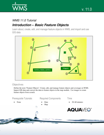
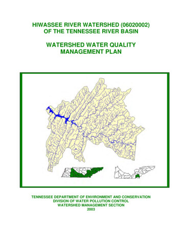
WMS TutorialsWatershed Modeling – Time of Concentration Calculations and Computing a Composite CN4Prepare the Basin for Use with NSSWe will now use WMS to calculate the basin area, basin slope, and other parameters thatcan be used in conjunction with NSS.1. Select DEM Compute Basin Data2. Select the Current Projection. button3. Set the Vertical units to Meters4. Select Set Projection5. Select METERS in the Planar Units Field6. Select OK7. Select OK8. Set the Basin Areas to Square miles9. Set the Distances to Feet10. Select OK to compute the parametersIn order to see the parameters that will be used with the NSS program, you can turn themon for display.11. Select Display Display Options12. Select Drainage Data13. Check the display toggle for Basin Slopes (Basin areas should already beon)14. Select OKBasin attributes are displayed at the centroid of the basin. In order to see the parametersmore clearly, turn off the display of the DEM15. If needed, expand the Terrain Data folder in the Project Explorer16. From the Project Explorer, toggle off the check box for the DEMYour screen should now look like Figure 4-1Page 3 of 14 Aquaveo 2012
WMS TutorialsWatershed Modeling – Time of Concentration Calculations and Computing a Composite CNFigure 4-1: Drainage basin with parameters computed5Calculating Percentage of Lake CoverThe regression equation for Region B of Florida includes a parameter (LK) to define theratio of the area of lakes in the basin to the total basin area (as a percent). We will use theCompute Coverage Overlay calculator in WMS to calculate the percentage of lake coverin our drainage basin. The only other parameter in the regression equation for Region Bof Florida is drainage area (DA), something that is automatically computed using theCompute Basin Data command.5.1Opening the Land Use CoverageIn order to compute the percentage of lake cover in our watershed, we will read in landuse data from a typical USGS land use file. Each polygon in the coverage is assigned aland use code that corresponds to a land use type. For this land use coverage, the codesfor water bodies (lakes, reservoirs, wetlands) include 52, 53, 61, and 62. We will look forthese codes to determine the value for LK.1. Right-click on the Coverages folder in the Project Explorer2. Select New Coverage3. Change the coverage type to Land Use4. Select OK5. Right-click on GIS layers and select Add Shapefile Data6. Open “valdosta.shp” and make it the active layerThis land use shapefile was obtained from www.webgis.com, but the EPA and otherwebsites contain similar information. Alternatively, we could have digitized land usepolygons from an image (discussed in Volume 1, Chapter 3: Basic Feature Objects).Page 4 of 14 Aquaveo 2012
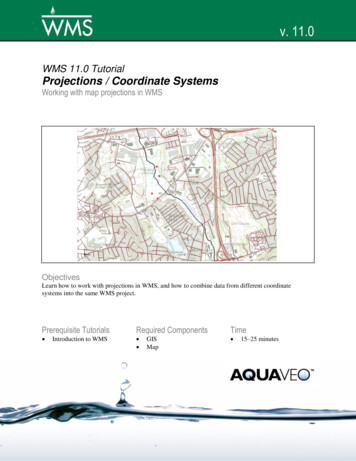
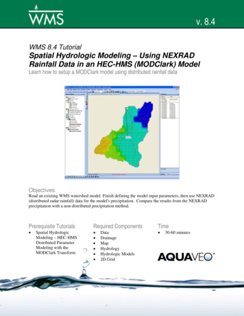
WMS TutorialsWatershed Modeling – Time of Concentration Calculations and Computing a Composite CN7. Choose the Select Shapes tool8. Drag a selection box around the drainage basin polygon9. Select Mapping Shapes - Feature Objects10. Select Next11. The LUCODE with the land use ID is automatically mapped so you cancontinue by selecting Next12. Select Finish13. Hide valdosta.shp by toggling off its check box in the Project Explorer(you may need to expand the GIS Layers folder to see it)Only the portion of the shapefile that was selected will be used to create polygons in theLand Use coverage. The following figure displays the resulting land use polygons andtheir respective land use codes. This land use classification is consistent among all of theUSGS land use data, where codes from 10-19 are urban, 20-29 agricultural, etc. Acomplete listing of code values can be found in the WMS Help file.Figure 5-1: Land use codes used in Valdosta.shp.5.2Using the Compute Coverage Overlay Calculator1. Switch to the Hydrologic Modeling module2. Select Calculators Compute Coverage Overlay3. Make sure that Drainage is chosen as the Input CoveragePage 5 of 14 Aquaveo 2012
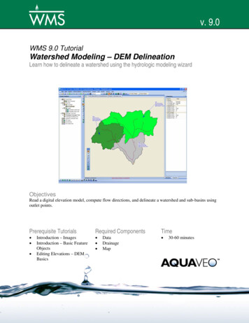
WMS TutorialsWatershed Modeling – Time of Concentration Calculations and Computing a Composite CN4. Make sure that Land Use is set as the Overlay Coverage5. Select the Compute buttonAccording to the USGS land use classification, code values in the 50’s and 60’s representwater bodies. To obtain the value for LK, we sum together the computed overlaypercentages for Land Uses 52, 53, 61, and 62, as shown in Figure 5-2.Figure 5-2: Summing the percentages of the codes representing water coverThe Coverage Overlay command can be used in a similar fashion to determine thepercentage of forested areas (codes in the 40’s), or any other classification type in a landuse file, or a soil file.6. Select Done6Running NSSThe geometric data computed from the DEM has automatically been stored with the NSSdata. You can now run a simulation using the derived data.1. Make sure that the Model combo box is set to NSS2. Select the Frame macro3. Select the Select Basin tool4. Double-click on the basin icon for Basin 1B5. Choose Florida from the list of states6. Highlight Region B from the list of Regional regression equations7. Select the Select- button to move Region B to the Selected Equationswindow8. Enter 10.8 for the Lake Area variable (you may have to scroll the VariableValues window in order to see the Lake Area variable)9. Select the Compute Results buttonThe peak flow (Q) values are displayed in the window at the bottom of the dialog.Page 6 of 14 Aquaveo 2012
WMS TutorialsWatershed Modeling – Time of Concentration Calculations and Computing a Composite CN6.1Exporting the Flow DataOnce flow data is computed it may be exported to a text file in the format shown in thewindow, along with pertinent information used in computing the peak flow values.1. Select the Export button2. Locate a directory, and define a name for the file3. Select SaveThe exported file can be viewed using any word processor, or inserted into a separatereport document.7Time Computation / Lag Time CalculationThe NSS program provides a way to determine an “average” hydrograph based on thecomputed peak flow and a basin lag time. A dimensionless hydrograph is used to define abasin hydrograph for the watershed based on the computed peak flow.1. Scroll down in the Results window if necessary, and select the line of textcorresponding to a Recurrence [years] of 502. Select the Compute Hydrograph button3. Select the Compute Lag Time - Basin Data button4. Change the Method combo box to the Custom Method (the very last one inthe list)5. Select OKThe computed lag time in minutes is shown in the lag time edit field. Time ofconcentration equations can also be used to calculate the basin lag time. WMS willconvert the time of concentration to lag time by the equation: Tlag 0.6*Tc6. Select the Compute Lag Time – Basin Data button7. Change the Computation type combo box to Compute Time ofConcentration8. Change the Method combo box to the Kerby Method for overland flow9. Select OKNote the difference in the calculated lag time between the two methods. These twoequations, along with the other available options in the Basin Time Computationcalculator, can be used to estimate the lag time of the basin. Compare the results of thedifferent equations available to best describe the characteristics of the basin.10. Select OK11. Select the Done buttonA hydrograph icon will appear next to the basin icon for Basin 1B. You can examine thehydrograph in more detail:12. Select the Select Hydrograph tool13. Double-click on the hydrograph iconPage 7 of 14 Aquaveo 2012
WMS TutorialsWatershed Modeling – Time of Concentration Calculations and Computing a Composite CNThe hydrograph is displayed in the Graphics window.14. Close the hydrograph plot window by clicking on the X in the upper rightcorner of the window15. Select File New16. Select No8Using TR-55 to Compute Tc and CNTravel times (time of concentration, lag time, and travel time along a routing reach) arecritical to performing analyses with any of the hydrologic models. You will learn of twodifferent ways WMS can be used to compute time of concentration for a TR-55simulation (lag times are computed in the same way): Runoff distances and slopes for each basin are automatically computedwhenever you create watershed models from TINs or DEMs andcompute basin data. These values can then be used in one of severalavailable equations in WMS to compute lag time or time ofconcentration If you want to have a little more control (and documentation) over thelag time or time of concentration, you will use a time computationcoverage to define critical flow paths. Time computation coveragescontain flow path arc(s) for each sub-basin. An equation to estimatetravel time is assigned to each arc and the time of concentration (or lagtime) is the sum of the travel times of all arcs within a basin. Lengths aretaken from the length of the arc and slopes derived if a TIN or DEM arepresent.In this exercise you will compute the time of concentration for the two sub-basins and thetravel time between outlet points in the watershed shown below. You will use the TR-55library of equations, but you could just as easily use one of the other pre-definedequations, or enter your own equation.9Reading a TR-55 ProjectYou will first read in a project file of an urban area that has been processed anddelineated as a single basin. The project includes a drainage coverage, a timecomputation coverage, and two shapefiles for the land use and soil type data.1. Switch to the Map module2. Select File Open3. Locate the folder \Tutorials\General WMS\tr-554. Open “suburbtr55.wms”Page 8 of 14 Aquaveo 2012
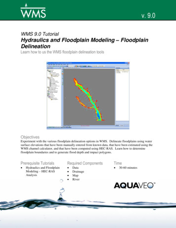
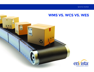
WMS TutorialsWatershed Modeling – Time of Concentration Calculations and Computing a Composite CN10Assigning Equations to Time Computation ArcsA flow path arc has already been defined for the basin. This arc represents the longestflow path for the urban area, starting from a sandy area at the top of the basin, followingalong the streets and down towards a detention pond at the bottom of the basin. The archas been split into four different segments to assign different equations to determine thetravel time for the arc. Use the following figure as a guide while defining the equations.Figure 10-1: Time Computation Arcs.1. Switch to the Time Computation coverage2. Choose the Select Feature Arc tool3. Double-click on the arc labeled A in Figure 10-1By default the arc will be a TR-55 sheet flow equation arc, so all you need to do is definethe overland Manning’s roughness coefficient and the 2yr-24hr rainfall. Length and slopewill already be entered (from the selected arc).4. Click on the Manning’s line in the Variables text window5. Enter a value of 0.03 in the Variable value edit window6. Click on the 2 yr - 24 hr rainfall line in the Variables text window7. Enter a value of 1.1Page 9 of 14 Aquaveo 2012
WMS TutorialsWatershed Modeling – Time of Concentration Calculations and Computing a Composite CNYou should notice in the Instructions/Results window that you are told what variablesneed to be defined before a travel time can be computed. Once you have entered all thenecessary values, this same window reports the travel time for this arc. In this way, youcan compute travel time for any arc segment no matter what the application is.8. Select OKYou have now defined an equation for the overland sheet flow segment in the basin andyou are ready to define the next segments as shallow concentrated flow.9. Double-click on the arc labeled B in Figure 10-110. Change the equation type to TR-55 shallow conc eqn11. Click on the Paved line in the Variables text window12. Enter ”yes” in the Variable value edit window13. Select OK14. Repeat for the arc labeled D, using the same equation type. In this case setthe Paved value to ”no”The remaining arc will be defined as an open channel flow arc.15. Double-click on the arc labeled C in Figure 10-116. Change the arc type to TR-55 Open channel eqn17. Click on the Manning’s n line18. Enter a value of 0.017 in the Variable value edit window19. Select the hydraulic radius line in the Variables windowPage 10 of 14 Aquaveo 2012
WMS TutorialsWatershed Modeling – Time of Concentration Calculations and Computing a Composite CN20. Select the Hydraulic Radius button to open up the WMS channelcalculations window so that the hydraulic radius can be computed fromestimates of the curb in the subdivision21. Select the Launch Channel Calculator button to launch the HydraulicToolbox Channel Calculator22. Change the Channel type to Triangular23. Enter a Side slope 1 (Z1) of 1024. Enter a Side slope 2 (Z2) of 0.0125. Enter a longitudinal slope of 0.010 ft/ft26. Choose the Enter depth option27. Enter a depth of 0.5 (an approximated depth since we do not know whatthe flow is at this point)28. Select the Calculate button29. Select OK for all three dialogsYou have now defined the necessary parameters for computing travel time using the TR55 open channel flow (Manning’s) equation. If you wish you can continue to experimentwith the channel calculator to compute the hydraulic radius rather than entering the givenvalues.You now have defined equations and variable values for each flow path segment. Youcan change these equations and variables, add new flow path segments, etc. in order todetermine the best flow paths and most appropriate equations for each basin. In otherwords, the process is subjective and it may take a few iterations to get the best value.11Computing Time of Concentration for a TR-55 SimulationBefore assigning time of concentrations to each basin you need to decide which modelyou want to use. For this exercise you will be running TR-55, but the same timecomputation tools you learn in this exercise could be used for any of the supported WMSmodels (such as in the TR-20 basin data dialog, the HEC-1 Unit Hydrograph methoddialog, and the Rational Method dialog).1. Select the Hydrologic Modeling module2. Change the Model drop-down list to TR-553. Select the Select Basin tool4. Select the basin5. Select TR-55 Run SimulationIn the TR-55 dialog, notice the two drop-down boxes at the top. These provide the abilityof changing TR-55 information for basins and outlets individually or collectively.6. Enter a Rainfall value of 1.57. Change the Rainfall distribution to Type IIPage 11 of 14 Aquaveo 2012
WMS TutorialsWatershed Modeling – Time of Concentration Calculations and Computing a Composite CN8. Select the Compute Tc - Map Data button. You will see the four timecomputation arcs that are in the basin9. You can create a detailed report as a text file if you want by selecting theExport Data or Copy to Clipboard buttons10. Select Done11. Select OKThe sum of the travel times for these arcs will be used as the time of concentrationfor this basinNote that you could bring up the time computation attributes dialog and change theequation or any of the equation variables by selecting the Edit Arcs button.12Computing a Composite Curve NumberIn this part of the exercise, you will learn how to overlay land use and soil coverages onyour delineated watershed in order to derive a curve number (CN).12.1Land Use TableNow you need to create a land use table with IDs and CNs for each type of land use onyour map. A table has been provided, but it is incomplete. To finish the table with all ofthe IDs and CNs for the shapefiles in the project, or just to edit the table in general,complete the following steps:1. Select File Edit File2. Open landuse.tbl3. If prompted, choose a text editor to edit the file with, by choosing Notepador another favorite editor in the Open With drop down list, and select OKIn the text editor, you will find three lines of text listing three IDs along with their CNvalues. The file format for this file is an ID value, followed by a comma, the name of theland use ID in quotation marks, followed by a comma, followed by the comma separatedCN values for soil types A, B, C, and D, respectively. This file includes CN values forlanduse types “Transportation, Communications”, “Other Urban or Built-Up Land”, and“Bare Ground”. The landuse shapefile in this project also contains landuse polygons forresidential areas, with an ID for 11. Complete the land use table by editing the file:4. Add the following line to the file: 11, "Residential", 61, 75, 83, 875. Save the file and close the editor12.2Computing Composite Curve NumbersIn order to compute composite curve numbers, WMS needs to know which type of soilunderlies each area of land. You will need either a landuse and soil type coverage, or alanduse and soil type shapefile with the appropriate fields. For this exercise, we will beusing landuse and soil type shapefiles.1. Select Calculators Compute GIS AttributesPage 12 of 14 Aquaveo 2012
WMS TutorialsWatershed Modeling – Time of Concentration Calculations and Computing a Composite CN2. Make sure the SCS Curve Numbers option is selected in the Computationsection of the dialog3. Select GIS Layers in the Using section of the dialog4. Select the Soil Layer Name to be soils poly.shp5. Make sure the Soil Group Field has been set to HYDGRP6. Select the Land Use Layer Name to be landuse poly.shp7. Make sure the Land Use ID Field has been set to LU CODEYou may have your land use and soil type tables stored in data files, such as the one youpreviously edited. Instead of manually assigning the data as you have here, you wouldread these tables in from this dialog using the Import button.Whether you have manually created tables or read them in from files, you should see theland use IDs and CNs for each soil type, and land use descriptions in the window of theMapping section.8. Select the Import button near the bottom of the dialog9. Find and open the mapping table “landuse.tbl”You should now see the assignment of CN values for the land use table previously edited.10. Select OK to compute the composite CNsA Runoff Curve Number Report is generated and opened automatically. The compositecurve number appears at the bottom of the report.11. Select the Select Basin tool12. Double-click on the basinNotice that the Curve number edit field has been updated with the calculated value fromthe Compute GIS Attributes dialog.13More TR-55While you were entering the data for the basin you may have noticed that instructions aregiven in the TR-55 data window to let you know what must be entered before a peak Qcan be determined. Once you enter all of the data the peak Q is computed and displayedin the same window. You can also get help for anything listed in the window.1. Notice that the TR-55 reference equation for computing peak flow isdisplayed next to Peak Discharge2. Select the Compute Hydrograph(s) button3. Select OK to close the TR-55 dialog4. Choose the Select Hydrograph tool5. Double-click on the hydrograph icon that is displayed by the upper basin toview the hydrograph in a separate windowPage 13 of 14 Aquaveo 2012
WMS TutorialsWatershed Modeling – Time of Concentration Calculations and Computing a Composite CN14ConclusionThis completes the chapter on using the time computation coverage to compute time ofconcentration and travel times and the land use and soil coverage to compute a compositeCN value. In the process you have also learned about the TR-55 interface.Page 14 of 14 Aquaveo 2012
First we will open a WMS Project file (*.wms) that contains a DEM that was previously downloaded from the Internet. A single watershed basin has been delineated from the DEM data and converted to feature objects. 1. Close all instances of WMS 2. Open WMS 3. Switch to the Drainage module 4. Select File Open 5.