Transcription
WMS TutorialsProjections / Coordinate Systemsv. 11.0WMS 11.0 TutorialProjections / Coordinate SystemsWorking with map projections in WMSObjectivesLearn how to work with projections in WMS, and how to combine data from different coordinatesystems into the same WMS project.Prerequisite Tutorials Introduction to WMSRequired Components GISMapPage 1 of 10Time 15–25 minutes Aquaveo 2019
WMS TutorialsProjections / Coordinate Systems123456781Introduction . 2Getting Started . 2Importing an Image . 33.1Setting the Projection . 33.2Setting Transparency . 4Importing a CAD File . 4Importing a Shapefile . 6Importing Elevation Data . 76.1Editing the Scatter Points . 9Creating a Coverage . 9Conclusion. 9IntroductionCoordinate systems and map projections provide information for locating data on theearth (georeferencing). There are two types of coordinate systems: geographic andprojected.A geographic coordinate system uses a three dimensional sphere to locate data on theEarth. Data in a geographic coordinate system is referenced using latitude and longitude.Latitude and longitude are angles measured from the Earth's center to a point on theEarth's surface.A projected coordinate system is two dimensional based on a sphere or spheroid. Unlikea geographic coordinate system, projected coordinate systems have constant lengths,angles, and areas across the two dimensions.1A PRJ file is a text file containing information describing the type coordinate system andother relevant data to position the related data on the Earth. This tutorial provides anoverview of working with projected data in WMS through the following steps:1. Importing a TIFF file and assigning a projection.2. Learning about the Display Projection.3. Importing a CAD file and assigning a different projection.4. Learning about “Project on the fly”.5. Importing a shapefile with an associated projection.6. Importing elevation data and edit points.7. Creating a coverage.2Getting StartedTo begin the tutorial, do the following:1. Launch WMS.1Information summarized from ex.cfm?TopicName projection basics the gis professional needs to knowPage 2 of 10 Aquaveo 2019
WMS TutorialIntroduction to WMS2. Select File New to restore program settings to the default state.3Importing an ImageStart by importing an image of an area where the model will be built. The image wasdownloaded from the state of Massachusetts.1. Click the Openbutton to bring up the Open dialog.2. Navigate to the Projections\Projections folder.3. Select “q233914.tif” and click Open to import the image and close the Opendialog.4. Move the mouse around in the Graphics Window.Notice that the lower right corner of the image is at x 233,000 and y 914,000 (which iswhere the file name “q233914” comes from). This image came with a TFW file (TIFFworld file); the world file gives the location and size of the pixels in the image file.No PRJ file was included with this image, so while WMS is able to read the world fileand position the image at the correct coordinates, WMS is not able to georeference thelocation of the image. The projection of the image must be specified in order togeoreferenced the image.3.1Setting the ProjectionTo set the projection in WMS:1. Right-click “ q233914.tif” in the Project Explorer and select Projection Projection to bring up the Projection dialog.2. In the Horizontal section, select the Global projection radio button to bring upthe Horizontal Projection dialog.This dialog is used to select a projection and can also be used to export or import PRJfiles.3. Enter “1983 Meters Massachusetts” in the Filter strings edit field.4. Select the “NAD1983 StatePlane Massachusetts FIPS 2001 (Meters)” item fromthe list.5. Click OK to exit the Horizontal Projection dialog.6. Click OK to exit the Projection dialog.7. Click OK at the warning that explains that a projection will be added to the file.8. Click Save from the Save As dialog to save the new TIFF file.9. Click OK if a warning dialog appears stating the display projection must be set.10. If the Display Projection appears, click OK.Projection data has now been added to the TIFF file. Any time this TIFF file is importedinto WMS (or any GIS application), it will use the set projection.Page 3 of 10 Aquaveo 2019
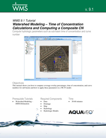
WMS TutorialIntroduction to WMSAny time the projection is set on an image, a new image will be exported fromGMS with the projection information stored in that image.11. Move the mouse around the Graphics Window.Notice that the coordinates are the same as before but now the latitude and longitude aredisplayed as the mouse movesWhen data which includes projection data is imported WMS, it will set the displayprojection. The display projection can be changed to any supported projection, thoughsome projections are not compatible. For example, data in State Plane, MassachusettsMainland will not display in the Philippines Grid.3.2Setting TransparencyThe transparency of the image must now be changed so that the other data brought intothe project will be easier to see.To do this:1. Right-click on “ q233814 exported.tif” in the Project Explorer and selectTransparency to bring up the Layer Transparency dialog.2. Use the slider to set Transparency to “60%”.3. Click OK to exit the Layer Transparency dialog.The project should appear similar to Figure 1.Figure 14Map image with 60% transparency appliedImporting a CAD FileTo import a CAD file with the roads in the study area, do the following:1. Select the Openbutton to bring up the Open dialog.Page 4 of 10 Aquaveo 2019
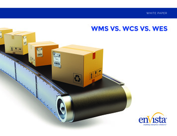
WMS TutorialIntroduction to WMS2. Select “roads.dwg” and click the Open button to import the file and close theOpen dialog.3. In the Project Explorer, right-click on “Extants.roads.dwg” and select Zoom toAfter importing the CAD file, the Graphics Window should appear as in Figure 2.Figure 2Imported CAD dataNotice that the background image has disappeared. By moving the mouse around in theGraphics Window, the displayed coordinates vary from (-71.15, 42.46) to (-71.09, 42.52),and the latitude/longitude values have changed.Because there was no PRJ file associated with this CAD file, the data is drawn at thecoordinates specified in the file. A projection for the CAD data must be specified so thatit will be drawn in the correct location. This particular file has coordinates inlatitude/longitude.To set the projection:4. Right-click on “ roads.dwg” in the Project Explorer and select Projection Projection to bring up the Projection dialog.5. In the Horizontal section, select Global projection and click the SetProjection button to bring up the Horizontal Projection dialog.Instead of searching the tree for the correct projection, enter the EPSG code to assign ageographic projection to the CAD data.6. Select the EPSG code button to open the Projection from EPSG code dialog7. Enter “4269” as the New EPSG code.8. Click OK to exit the Projection from EPSG code dialog.9. Click OK to exit the Horizonatal Projection dialog.10. Click OK to exit the Projection dialog.11. Click OK at the warning that explains that a projection will be added to the file.Page 5 of 10 Aquaveo 2019
WMS TutorialIntroduction to WMS12. Right-click on “Extents.roads.dwg” in the Project Explorer and select Zoom toThe image should now be visible behind the CAD data (Figure 3). Even though the CADdata is in a different projection from the display projection, it is positioned in the correctlocation. The CAD data is “projected on the fly”, which involves transforming thecoordinates of the CAD data from latitude and longitude to State Plane meters.Items with a projection different from the display projection are “projected onthe fly” so that they are positioned correctly.Figure 3CAD correctly positioned after specifying the projectionIf the CAD file had initially had an associated PRJ file, then the data would have alreadybeen correctly positioned in the current display projection.When opening the Horizontal Projection dialog, notice that a list of recently usedprojections is shown. This can be useful when assigning the same projections to multipleobjects. Likewise, frequently used projections can be saved by right-clicking on theprojection and selecting Add to Favorites which will then show the projection under thefavorite projections folder.5Importing a ShapefileA shapefile of the Aberjona River will now be imported. This shapefile uses a differentprojection than the display projection.To import the shapefile:Page 6 of 10 Aquaveo 2019
WMS TutorialIntroduction to WMS1. Click the Openbutton to bring up the Open dialog.2. Select “AberjonaRiver Clip.shp” and click Open to import the file and close theOpen dialog.The Graphics Window should appear as in Figure 4.Figure 4Aberjona River shapefile3. Right-click on “ AberjonaRiver Clip.shp” in the Project Explorer and selectProjection Projection to bring up the Projection dialog.Note the projection is “NAD 1983 UTM Zone 18N”, which was imported from thePRJ file associated with the shapefile. This allowed WMS to place the shapefile in thecorrect location.4. Select Cancel to exit the Projection dialog.If a file is imported imnto WMS, and the file has an associated PRJ, then theprojection is imported with the file.6Importing Elevation DataNext to import surface elevations into the project from a text file by doing the following:1. Select the Openbutton to bring up the Open dialog.2. Select “elev.txt” and click Open to close the Open dialog and open the TextImport Wizard – Step 1 of 2 dialog.Page 7 of 10 Aquaveo 2019
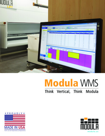
WMS TutorialIntroduction to WMS3. Below the File import options section, turn on Heading row.4. Click the Next button to bring up the Text Import Wizard – Step 2 of 2 dialog.5. Select “2D scatter points” for the WMS data type.6. Click the Finish button to close the Text Import Wizard – Step 2 of 2 dialog.To set the projection to make the scatter set display correctly, do the following7. Right-click on “ elev” in the Project Explorer and select Projection Projection to bring up the Projection dialog.8. In the Horizontal section, select Global projection and click on the SetProjection button to bring up the Horizontal Projection dialog.9. Click the .prj file button to bring up the Open dialog.10. Browse to the Projections\Projections directory and select “elev.prj”.11. Click Open to close the Open dialog.12. Click OK to close the Horizontal Projection dialog.13. Click OK to close the Projection dialog.14. Select “elev” in the Project Explorer and click the Framemacro.The Graphics Window should appear similar to Figure 5.Figure 5Imported elevation dataPage 8 of 10 Aquaveo 2019
WMS Tutorial6.1Introduction to WMSEditing the Scatter PointsThe elevations that are in the project can be edited as follows:1. Select “elev” in the Project Explorer to make it active.2. Using the Select Scatter Pointtool, select one of the scatter points in theGraphics Window by clicking on it.3. Press the Delete key to delete the selected point. A prompt appears that explainsthat the projection of the “elev” scatter set does not match the display projection.In order to edit the points, the scatter set’s projection must be the same as thedisplay projection.4. Select Yes at the prompt to change the display projection to match that of the“elev” scatter set projection.5. Framethe project.6. Press the Delete key again to delete the selected point.An item in a project can be edited only if its projection matches the displayprojection.7Creating a CoverageA coverage can be created by doing the following:1. Right-click on “ Coverages” in the Project Explorer and select NewCoverage to bring up a Properties dialog.2. Click OK to accept the default settings and exit the Properties dialog.3. Right-click on “ new coverage” and select Projection Projection to bringup the Projection dialog.4. Notice that the projection for this coverage is the same as the Display Projection.Click OK to exit the Projection dialog.When a new item is created in a WMS project, the projection of the new itemwill be set to match the Display Projection.8ConclusionThis concludes the “WMS Projections / Coordinates Systems” tutorial. The followingitems were discussed in the tutorial: WMS supports many different projections. WMS has a user-defined display projection. An item’s projection can be specified in WMS and the file will be overwritten. All georeferenced data in a WMS project is drawn in the display projection; thisrequires “Projecting on the fly”.Page 9 of 10 Aquaveo 2019
WMS TutorialIntroduction to WMS Newly created items in a WMS project are assigned the display projection bydefault. To edit an item in a WMS project, the item’s projection must match the displayprojection.Page 10 of 10 Aquaveo 2019
WMS 11.0 Tutorial Projections / Coordinate Systems Working with map projections in WMS Objectives Learn how to wor k with projections in WMS, and how to combine data from different coordinate systems into the same WMS project. Prerequisite Tutorials