Transcription
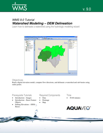
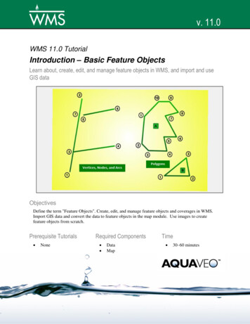
Introduction – Basic Feature ObjectsWMS Tutorialsv. 11.0WMS 11.0 TutorialIntroduction – Basic Feature ObjectsLearn about, create, edit, and manage feature objects in WMS, and import and useGIS dataObjectivesDefine the term "Feature Objects". Create, edit, and manage feature objects and coverages in WMS.Import GIS data and convert the data to feature objects in the map module. Use images to createfeature objects from scratch.Prerequisite Tutorials NoneRequired Components DataMapPage 1 of 15Time 30–60 minutes Aquaveo 2018
Introduction – Basic Feature ObjectsWMS 671Introduction . 2Getting Started . 3Creating and Editing Feature Objects . 3Creating Feature Arcs . 4Inserting Vertices and Snapping Arcs . 4Deleting an Arc . 5Converting Vertices to Nodes . 5Converting Nodes to Vertices . 6Building Polygons . 6Assigning Attributes . 7Using Shapefiles to Create Feature Objects . 8Importing a Shapefile and Mapping to Feature Objects . 9Using Background Images to Create Feature Objects . 10Create a New Coverage . 11Importing Images . 11Manually Digitizing Feature Objects . 11Assigning Feature Polygon Attributes . 13Display Options . 14Conclusion . 15IntroductionFeature objects are points, lines, and polygons organized in coverages by differentattribute sets such as drainage features, land use, soils, travel time paths, cross sections,and so on. The primary coverage in WMS is the drainage coverage, which holds drainageboundary polygons, stream lines, and outlet nodes. Most of the other coverages aresecondary to the drainage coverage and are used to “map” other hydrologic parameterssuch as travel time or curve numbers.Feature objects are equivalent to GIS vector data. Importing from GIS databases is oneway to create coverages in WMS. Feature object coverages can also be digitized directlyfrom the screen, using a georeferenced image in the background as a guide. This tutorialdemonstrates both methods, focusing on using various tools and assigning attributes.This tutorial teaches the basics of creating and importing feature objects and managingdifferent coverages. It discusses and demonstrates: Creating and editing feature objects Defining feature object attributes Creating coverages Specifying attribute sets Using shapefiles Using images to create feature objects Managing multiple coveragesPage 2 of 15 Aquaveo 2018
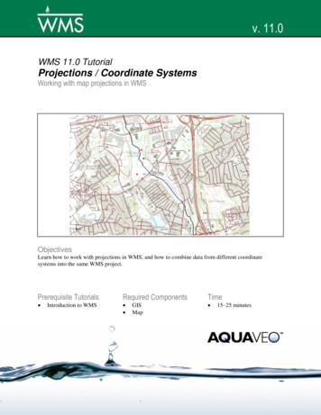
Introduction – Basic Feature ObjectsWMS Tutorials2Getting StartedLaunching WMS at the beginning of each tutorial is recommended. This resets the data,display options, and other WMS settings to their defaults. To do this:1. If necessary, launch WMS.2. If WMS is already running, press Ctrl-N or select File New to ensure that theprogram settings are restored to their default state.3. A dialog may appear asking to save changes. Click Don’t Save to clear all data.The graphics window of WMS should refresh to show an empty space.4. Switch to the Map5. Click Openmodule.to bring up the Open dialog.6. Browse to the feature\feature\ folder and select “FeatureObjects.jpg”.7. Click Open to import the image and exit the Open dialog.An image similar to Figure 1 will appear in the Main Graphics Window. This imagedepicts different examples of feature objects. This tutorial will use them to trace andcreate feature objects.Figure 13Example feature objects depicted in the imported imageCreating and Editing Feature ObjectsThe Terrain Data , Drainage , and Mapmodules are where the feature objectsare created and manipulated. All feature objects are made from a set of points and thelines (arcs) connecting the points. There are three main types of feature objects: points,arcs, and polygons. The following sections show how to create and edit the differenttypes of feature objects.Page 3 of 15 Aquaveo 2018
Introduction – Basic Feature ObjectsWMS Tutorials3.1Creating Feature ArcsUse the “Vertices, Nodes, and Arcs” section of Figure 1for sections 3.1 through 3.5.While creating a feature arc, press Esc to cancel, Backspace to back up one vertex, Enteror single-click to make a vertex, and double-click to end the arc. When WMS creates anarc, each end is a node and all points in the middle are vertices.1. Select “Drainage” in the Project Explorer to make the coverage active.2. Using the Create Feature Arctool, click on the image near point “1”.3. Double-click on the image near point “2” to end the arc.4. Click at point “3”, directly on top of the newly created arc.5. Double-click at point “4” to end the arc.Notice how WMS automatically links the new arc to the existing arc and creates a node atthe point of intersection, splitting the existing arc into two arcs.6. Click at point “5”.7. Double-click at point “6”.3.2Inserting Vertices and Snapping ArcsIf two arcs very close to each other should share a common node, WMS has a tool tosnap these nodes together.1. Click Display Optionsto bring up the Display Options dialog.2. Select “Map Data” from the list on the left.3. On the Map tab, turn on Vertices and click on the button to the right of the checkbox to bring up the Point Properties dialog.4. Enter “5” as the Radius.5. Click OK to close the Point Properties dialog.6. Click OK to close the Display Options dialog.7. Using the Create Feature Vertexis labeled “7”.tool, click on the first arc next to where itA vertex is inserted here, making it possible for the “5-6” arc to be “snapped” to thislocation.8. Using the Select Feature Point/Nodetool, right-click on node “5” and selectClean to bring up the Clean Options dialog.9. Turn on Snap selected nodes.10. Click OK to close the Clean Options dialog.At the bottom left of the WMS screen, notice the prompting to “Select a snappingpoint ” (Figure 2).11. Select the newly created vertex “7”.Page 4 of 15 Aquaveo 2018
Introduction – Basic Feature ObjectsWMS TutorialsFigure 2Select a snapping pointWMS snaps the two arcs together and changes vertex “7” to a node (Figure 3).Figure 33.3Vertex 7 becomes Node 7 after snapping Node 5 to itDeleting an ArcNow that the main arc has two nodes along its length, delete the center arc only.1. Using the Select Feature Arctool, select the arc between nodes “3” and “7”.Notice that WMS highlights the selected arc.2. Press the Delete key—or right-click and select Delete —to delete the arc.3. If asked to confirm deleting the arc, click OK .Arcs can be created between two existing nodes by doing the following:4. Using the Create Feature Arctool, click on node “3”.5. Click on node “7” to re-form the arc.3.4Converting Vertices to NodesWMS uses vertices and nodes for different purposes. For example, nodes can haveattributes while vertices simply define the shape or position of the arc. Changing a vertexto a node—or a node to a vertex—is sometimes necessary.1. Using the Create Feature Vertexbetween nodes “3” and “7”.tool, click on the 3–7 arc anywhereA dot should appear, indicating the location of the new vertex.2. Using the Select Feature VertexVertex Node.Page 5 of 15tool, right-click on the new vertex and select Aquaveo 2018
Introduction – Basic Feature ObjectsWMS TutorialsA red node should appear at this location (Figure 4). The 3–7 arc is now broken in half. Itis now possible to define attributes (e.g., a drainage outlet) at this location.Figure 43.5The new node appears as a red dot below Node 7Converting Nodes to VerticesJust as vertices can be changed to nodes, nodes can be changed to vertices. Doing so canleave the project with a cleaner representation of its feature arcs. For example, instead ofmanaging and assigning attributes to two arcs, converting a node to a vertex merges thetwo arcs together.1. Using the Select Feature Point/Nodeselect Node Vertex.tool, right-click on the new node andThe node has been changed back to a vertex.3.6Building PolygonsFor this section, use the “Polygons” section on the imported image.1. Using the Create Feature Arctool, click on point “1” of polygon “A”.2. Click on points “2” through “10” and then click again on point “1” to close thearc.3. Click Yes if a warning appears asking to convert the arc to a generic feature arc.4. Do the same for points “1” through “3” on polygon “B”.Now there are two closed arcs. To change them into polygons, do the following:5. Right-click on the “Build Polygon.Drainage” coverage in the Project Explorer and select6. Click OK when asked to use all arcs.The two polygons should now be drawn with a thicker line instead of the thinner arc lines(Figure 5). Polygons are built from their constituent arcs. The appropriate topology isestablished when the polygon is built.Page 6 of 15 Aquaveo 2018
Introduction – Basic Feature ObjectsWMS TutorialsFigure 53.7The polygons have thicker linesAssigning AttributesEach of the nodes, arcs, and polygons were created with default properties or attributes.WMS allows changing the attributes of feature objects.1. Using the Select Feature Arctool, hold down the Shift key and select all fivearcs in the “Vertices, Nodes, and Arcs” section of the image.2. Select Feature Objects Attributes to bring up the Feature Arc Type dialog.This dialog allows choosing the type of arc for the selected arc(s).3. Select Stream and click OK to close the Feature Arc Type dialog.4. Turn off “FeatureObjects.jpg” in the Project Explorer.5. Click anywhere outside of the feature objects to deselect all of them.6. Click Display Optionsto bring up the Display Options dialog.7. Select “Map Data” from the list on the left.8. On the Map tab, scroll to the bottom of the list below the Coverage type dropdown and turn on Stream Arrows.9. Click OK to close the Display Options dialog.Notice that the arcs are now colored blue. Each arc portion should have a blue arrowindicating flow direction for the stream. The original direction in which the arc wascreated determines the way the stream flows (though the flow direction can be reversed).It is best practice to create stream arcs from downstream to upstream.Notice that the lower node on the arc looks different now. WMS has automaticallychanged it to a drainage outlet instead of a generic node.Page 7 of 15 Aquaveo 2018
Introduction – Basic Feature ObjectsWMS Tutorials10. Using the Select Feature Point/Nodetool, double-click on the lower outletnode (Feature Point ID “2C”) to bring up the Drainage Feature Point Typedialog.Notice that in the Type section, Drainage outlet is selected. This dialog can be accessedby selecting any feature object (point, line, or arc) and then selecting Feature Objects Attributes or by double-clicking on the object.11. Click OK to close the Drainage Feature Point Type dialog.Just as the attributes of arcs and nodes can be changed, the attributes of polygons can bechanged.12. Using the Select Feature Polygontool, double-click anywhere insidepolygon “A” to bring up the Drainage Feature Polygon Type dialog.13. In the Type section, select “Drainage boundary” and click OK to close theDrainage Feature Polygon Type dialog.The boundary of polygon “A” should remain a thick colored line (Figure 6).14. Double-click anywhere inside polygon “B” (the triangle) to bring up theDrainage Feature Polygon Type dialog.15. In the Type section, select Lake/Reservoir and click OK to close the DrainageFeature Polygon Type dialog.16. Click outside either polygon to deselect all polygons.Polygon “B” should have a light blue border (Figure 6).Figure 64Polygons after the type attribute is setUsing Shapefiles to Create Feature ObjectsOne of the most important features of WMS is the ability to automatically create featureobjects using shapefiles. Importing shapefile data can be done in different ways.Page 8 of 15 Aquaveo 2018
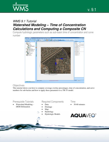
Introduction – Basic Feature ObjectsWMS TutorialsAdditional options may be available, depending on which external software (e.g.,ArcGIS) is installed.Before proceeding, reset to a blank project.1. Click New.2. Click Don’t Save when asked to save changes.4.1Importing a Shapefile and Mapping to Feature Objects1. Switch to the GISmodule.2. Right-click on “ GIS Data” in the Project Explorer and select Add ShapefileData. to bring up the Select shapefile dialog.3. Select “streams.shp” and click Open to import the shapefile and close the Selectshapefile dialog.The shapefile should appear similar to Figure 7. Note that the DBF and SHX files (in thiscase, “streams.dbf” and “streams.shx”) must always be in the same directory as the SHPfile or the shapefile will not work properly.Figure 7The imported shapefile showing the drainage basin4. Using the Select Shapesselect them all.tool, click and drag a box around all the shapes to5. Select Mapping Shapes Feature Objects to bring up the Step 1 of 3 page ofthe GIS to Feature Objects Wizard dialog.This dialog is used to map shapefile data to feature objects in WMS.6. Click Next to go to the Step 2 of 3 page of the GIS to Feature Objects Wizarddialog.The spreadsheet shows each shapefile attribute in capitalized letters (e.g., DRAINTYPE,LENGTH, SLOPE, and so on). Underneath each attribute is a drop-down containing theWMS attributes available to map to the shapefile attributes.Page 9 of 15 Aquaveo 2018
Introduction – Basic Feature ObjectsWMS Tutorials7. In the Mapping Preview section on the Mapping row of the spreadsheet, select“Drainage Arc type” from the drop-down in the DRAINTYPE column.8. Select “Stream Length” from the LENGTH drop-down.9. Select “Stream slope” from the SLOPE drop-down.10. Select “Not mapped” from the DMANNINGS drop-down.This attribute cannot be mapped because there is not a corresponding WMS attributeavailable to map it to because it is not an attribute of a feature object in WMS.11. Select “Stream basin id” from the BASINID drop-down.Review the values assigned to each attribute for each shape in the spreadsheet.12. Click Next to go to the Step 3 of 3 (Finished) page of the GIS to Feature ObjectsWizard dialog.13. Click Finish to close the GIS to Feature Objects Wizard dialog.14. Turn off “streams.shp” in the Project Explorer.The shapefile containing streams and basins has been imported, with all the shapesconverted to WMS feature objects. The data from the original shapefile has been mappedto WMS attributes (Figure 8).Figure 85Shapefile mapped to feature objectsUsing Background Images to Create Feature ObjectsWMS enables the creation of feature objects using background images as guides—forinstance, importing a soil use map into WMS.Before proceeding, reset to a blank project.1. Click New.2. Click Don’t Save when asked to save changes.Page 10 of 15 Aquaveo 2018
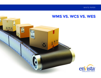
Introduction – Basic Feature ObjectsWMS Tutorials5.1Create a New CoverageNotice the default coverage, “ Drainage”, listed under the “ Map Data” folder in theProject Explorer. This is the default coverage automatically created in any new project inWMS. The Project Explorer enables management the default coverage, the ability tomake new coverages, delete coverages, edit coverage properties, and change the activecoverage.1. Right-click on “Drainage” and select Rename.2. Enter “PracticeDrainage” and press Enter to set the new name.3. Right-click on “ Coverages” and select New Coverage to bring up theProperties dialog.4. Select “Soil Type” from the drop-down on the Coverage type row in the Valuecolumn.Notice that the Coverage name in the field below automatically changes to “Soil Type”.5. Click OK to close the Properties dialog and create the new coverage.6. Select the “5.2Soil Type” coverage to make it active.Importing ImagesNow that a soil type coverage has been added, import the soils image.1. Click Opento bring up the Open dialog.2. Select “Image Files (*.img)” from the Files of type drop-down.3. Select “soils.img” and click Open to import the image and exit the Open dialog.A soils image similar to Figure 9 should appear.Figure 95.3Soils image showing different soil typesManually Digitizing Feature Objects1. Select the “Soil Type” coverage to make it active.Page 11 of 15 Aquaveo 2018
Introduction – Basic Feature ObjectsWMS Tutorials2. Using the Create Feature Arctool,3. Starting anywhere on the border of the large orange area (labeled “D”), outlinewith an arc the entire region.4. Create arcs for all the other soil type areas, being careful to not create arcs on topof previously defined borders.Zoomin to get a closer view of the image if needed. End an arc by double-clicking inorder to be able to select any other tools, such as Zoom , Pan , or show all. Whenoutlining each soil region, simply start on a previously created arc and proceed aroundeach border, ending when another previously created border is reached. When clickingnear an existing vertex or arc, WMS automatically snaps the new arc to the existing one.The resulting arcs should appear similar to Figure 10.Figure 10All of the soil areas defined with closed arcs5. Right-click on the “Soil Type” coverage and select Build Polygon.6. Click OK to use all the arcs.Check to make sure that each soil use polygon is completely outlined. If one or morepolygons do not build correctly, check to be sure that the arcs surrounding the polygonsare completely closed. The resulting polygons should appear similar to Figure 11. Noticehow the polygon borders are thicker than the closed arcs.Page 12 of 15 Aquaveo 2018
Introduction – Basic Feature ObjectsWMS TutorialsFigure 115.4After the polygons are builtAssigning Feature Polygon AttributesNow that the soil use polygons have been created, assign the soil use attributes to thecorrect polygons.1. Using the Select Feature Polygontool, double-click on the largest yellowpolygon labeled “B” to bring up the Soil type mapping dialog.Double-clicking on a feature object brings up a dialog allowing the selection or editing ofits attributes. Because a “Soil Type” coverage is being used, the automatic attribute for apolygon is “Soil Type”.2. In the WMS soil ID section, click Add soil ID to list to create a new entry in thelist above the button.3. Repeat step 2 until there are four entries in the list above the button.Now assign soil types to the WMS Soil IDs.4. In the Soil type properties section, select “Type A” from the drop-down in theSoil ID 1 column.5. Select “Type B” from the drop-down in the Soil ID 2 column.6. Select “Type C” from the drop-down in the Soil ID 3 column.7. Select “Type D” from the drop-down in the Soil ID 4 column.8. Since the polygon selected was Type B (and was therefore labeled “B” on theimported image), select “Soil ID 2” from the WMS soil ID list and click Apply.9. Double-click on the smaller yellow polygon on the right edge of the image andrepeat steps1 and 8.10. Double-click on the polygon labeled “A” and repeat steps1 and 8, insteadassigning “Soil ID 1”.11. Repeat steps1 and 8 for the three polygons labeled “C”, assigning “Soil ID 3”.12. Repeat steps1 and 8 for the two polygons labeled “D”, assigning “Soil ID 4”.Page 13 of 15 Aquaveo 2018
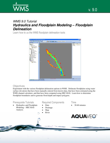
Introduction – Basic Feature ObjectsWMS TutorialsIt is recommended to recheck the soil types to make sure they have been entered correctly,especially on larger projects with many different types.6Display OptionsWMS has many display options to help tailor the look of a project. It is possible tochange options such as polygon colors, presence of nodes and vertices, and legends usingthe Display Options command.1. Right-click on the “ Soil Type” coverage and select Display Options tobring up the Display Options dialog.2. Select “Map Data” from the list on the left.3. On the Map tab, turn on Color Fill Polygons and Soil Type Legends.4. Turn off Points/Nodes and Vertices.5. Click Soil Type Display Options to bring up the Soil Type Display Optionsdialog.6. Select “Soil ID 1” from the list on the left and click the Patternbutton.7. Select “Red” from the list of colors.8. Repeat steps 6–7 for “Soil ID 2”, “Soil ID 3”, and “Soil ID 4”, setting them to“Blue”, “Green”, and Yellow”, respectively.9. Click OK to close the Soil Type Display Options dialog.10. Click OK to exit the Display Options dialog.11. Turn off “soils.tif” in the Project Explorer.The Graphics Window should appear similar to Figure 12.Figure 12Soil types with new display colorsPage 14 of 15 Aquaveo 2018
Introduction – Basic Feature ObjectsWMS TutorialsFeel free to continue to exploring the display options. To assign new colors to the landuses, select the “ Land Use” coverage before opening the Display Options dialog, orselect “Land Use” from the Coverage type drop-down on the Map tab of the DisplayOptions dialog.7ConclusionThis concludes the “Introduction – Basic Feature Objects” tutorial. The basics forcreating and importing feature objects and managing different coverages were covered.Both these concepts are central to an understanding of WMS.The following key concepts were also discussed and demonstrated: Create and edit feature objects Set feature object attributes Create coverages and specify coverage attribute sets Import shapefiles Use images to create feature objects Manage multiple coveragesPage 15 of 15 Aquaveo 2018
Launching WMS at the beginning of each tutorial is recommended. This resets the data, display options, and other WMS settings to their defaults. To do this: 1. If necessary, launch WMS. 2. If WMS is already running, press Ctrl-N or select File New to ensure that the program settings are restored to their default state. 3.