Transcription
Machine Monitoring SystemsDigital Overspeed Protection Systemwith PROFIBUS -DP interfaceDOPS, DOPS AS, DOPS TS Systems DOPS and DOPS AS SIL3-certified PROFIBUS-DP Interface: (optional) Microcontroller based 3-channelmeasuring system High safety level due to passwordprotection at each of the monitors Up to 6 limit values per channel Two current outputs per channel with zoom and dual current function, oneof them electrically isolatedMutual comparison of pulses andoutput signals between all channelsRedundant power supplies formonitors and backplaneSelf-test functions for electroniccircuits and sensorsSimplified fault detection by displaymessages in plaintextElectrical isolation of binary input andoutput signalsWiring by means of preformed cablesand converters in the control cubicleRS 232 interface for input ofparametersRS 485 interface for data exchangewith the host computerHot swap of boards during operationApplication:The speed measurement andoverspeedprotectionsystemsDOPS and DOPS AS serve themeasurement of speeds and theprotectionofinadmissibleoverspeeds at rotating machines.The DOPS systems in combination with safety shut-off valvesare suitable to replace oldermechanical overspeed protectionsystems.With the consistent three channeldesign, starting with the signaldetection via signal processing upto the evaluation of the measuredspeed, the system offers themaximum safety for the machinesto be monitored.Safety relevant limit values (e.g.overspeed limits) are submitted tothepost-connectedfail-safetechnique.Thus it can be ensured that besideoperational safety, the protectionfunction on a high level standard ismet as well.The integrated peak value memorypermits reading out the maximumspeed value that has occurredbefore the machine was switchedoff. This function provides importantinformation for evaluating themechanical machine load causedby the overspeed.Alarmoutputsanderrormessages are output as potentialfree relay outputs and as shortcircuit proof 24 V voltage outputs.The alarm outputs, combined in 2out of 3 logic, are also available aspotential free relay contacts.The system includes an extendedfault detection function. The threespeed sensors are continuouslychecked on operating within thepermitted limits.Moreover, the channels mutuallycheck and supervise the outputsignals of each other. If the internalfault detection circuit detects an error,this will be indicated via the outputcontacts and shown on the display asplaintext.By means of the the PROFIBUS DPinterface the recorded data can bepassed on to host computers.By using prefabricated connectioncables and screw terminals, thesystemsmaybeintegratedeconomically in 19“ cabinets.Page 1 of 8
Machine Monitoring SystemsSystem lines of the DOPS system:For the measurement of speed andfor the protection from overspeeds,epro offers three system variants.System DOPSThis system offers a maximum infunctionalityandiscertifiedaccording to SIL3 – DIN EN 61508in combination with epro MMSeddy current measuring chains. Itrequires the following components:-3 x monitor MMS 6350 (/DP)(incl. firmware applic. no. 0)Profibus-interface (optional)or alternatively3 x monitor MMS 6350D (/DP)(incl. firmware applic. no. 0)with speed displayProfibus-interface (optional)In addition:1 x Backplane MMS 6351/001 x 19“ frame MMS 63526 x screw terminals MMS 63616 x cable 0.5 m MMS 6362alternativelycable 3 m MMS 63601 configuration kit MMS 69503 x blind plate BLE 008, for theinstallation of monitors withoutdisplayWhen using this system line, thereareadditionalcombinationsavailable via relay outputs besidethe normal outputs of the alarmsOUT1.OUT6 and the systemsupervision Channel Clear:2 v 3 combination output OUT12 v 3 combination output OUT22 v 3 combination output OUT32 v 3 combination Channel Clear1 v 3 combination Channel ClearSystem DOPS ASIn addition:1 x Backplane MMS 6351/101 x 19“ frame MMS 63526 x screw terminal MMS 63616 x cable 0.5 m MMS 6362alternativelycable 3 m MMS 63601 configuration kit MMS 69503 x blind plates BLE 008, forthe installation of monitors without displayModule supervisionSensor supervisionAll three DOPS system lines offer thesame extensive system supervisionfunctions.Reasons for module disturbancescan be read out in detail via thecommunication interface or, atmodules with a display, directly onthe display.When using this system line,there are additional combinationsThis permits the technicians toavailable via relay outputs besiderecognize the reason for the faultthe normal outputs of the alarmsimmediately.OUT1.OUT6 and the systemDuring the change from the error tosupervision Channel Clear:the ok-state and after power-on of the2 v 3 combination output OUT2module, all functions of the module2 v 3 combination output OUT4are blocked for a delay time of 5 sec.OUT5 ( TRIP CC) channel ADepending on the backplane usedOUT5 ( TRIP CC) channel Bor the installed firmware, theOUT5 ( TRIP CC) channel Cindication of faults or overspeeds ismade via function-outputs and besidethis via relay outputs with 2 out of 3combinations of the alarm outputs.System DOPS TSThis system line is used to replaceAEG-Turloop systems.For the redesign on this system, thespeed monitors MMG 1222 TS areremoved from the slots andreplaced by MMS 6350 MMS 6353each.The old, existent Turloop frameremains in the rack, it is notnecessary to change the wiring.The followingrequired:componentsThe systems DOPS and DOPS ASoffer the following supervisionfunctions:Pulse comparisonAnalog comparisonGap supervision(Not for DOPS TS)are Sensor supervision:(Short-circuit, interruption)-3 x monitor MMS 6350 (incl.firmware appl. no. 1)In addition:3 x adapter MMS 6353 TS1 configuration kit MMS 69501 set of blind plates MMS 6354Sensor signal levelSensor supply currentSystem supply voltagesThis system offers a specialfunctionality for Astom applicationsand is certified according to SIL3 –DIN EN 61508 in combination withepro MMS eddy-current measuringchains. This system line requiresthe following components:System Watch-DogThe DOPS TS system replacesthe functions of the old Turloop Internal temperaturesystem. With this system line notall functions of DOPS or DOPSAS are at disposal.-The DOPS TS system is notcertified according to SIL3, DINEN 61508.-3 x monitor MMS 6350 (/DP)(incl. firmware appl. no. 2)Profibus interface: (optional)alternatively3 x monitor MMS 6350D (/DP)(incl. firmware appl. no. 2)with speed displayProfibus interface (optional)The Profibus-interface is notavailable for system line DOPSTS.Page 2 of 8
Machine Monitoring SystemsTechnical Data:Signal input:Max. speed:diff. input, non-reactive, open65.535 rpmMax. number of teeth:circuit and short-circuit proofInput voltage range:255 (with Nmax 4700 rpm)0.30 VdcCurrent outputs –Input resistance:Characteristical values: 100 kOhmCalculation of characteristicalSensor signal output:values and evaluation deFront socket SENS.pend on the functions definedduring the configurationdecoupled, open circuit and shortCurrent output 1 (Iout1):circuit proof, non-reactive, not0/4.20 mA / 20.4/0 mAcalibrated, in phase with sensorelectrically isolatedsignalMeasuring error:Voltage range: 0.4,1VppAmplitude 0,1% of full scale,16 bit resolutionSensor signal x (-0,15)Accuracy:Current output (Iout2): 1% of full scale(Not available for DOPS TS)Frequency range:0/4.20 mA / 20.4/0 mA0.16 kHz (-3 dB) 20 %Permissible load resistance:with reference to internalGND, with feed back of this 1 MΩInternal resistance:output signal for internal comparison of analog values10 kOhmAccuracy:Dynamic outputs: 0,1% of full scaleFront socket pulses16 Bit resolutionSpeed zoom function:The processed input pulses areprogrammable speed zoomoutput as TTL – pulses.function for each of theopen circuit and short-circuitcurrent outputsproof, non-reactiveNominal range:ChannelsupervisionandTTL – level, 5 VSSvisualization:Frequency range:Every channel permanently0 Hz.20 kHzPermissible load resistance:checks the signal of the speedsensor and compares signal 1 MΩInternal resistance:pulses and current output withthe signals of the other5,1 kΩchannels. Thus a maximum inPulse outputsafety can be ensured.Pulse-C, Pulse-EFaults are indicated with two(Not available for DOPS TS)green LEDs at the monitor front.Signalling of the channelThe processed input pulses aresupervision is carried out viaoutput via potential-free optoopto-decoupled voltage outputscoupler outputs. The pulses are(function outputs).in phase with the input signalMax. voltage (DC7):Output „Channel Clear“ 48 Vdc on collectorMax. current with C-E conOperating mode open circuit orducting:closed circuit mode freelyselectable.Current limitation on 25 mAVoltage outputSignalconditioningofthe 24 VDC High statecharacteristic values:0 VDC Low stateMax. CurrentBefore processing by theprocessor, the input signals are25 mA (current limitation)standardized. The characteristicvalue is proportional to the Binary ,commonMax. measuring range::reference point.limited o 20 kHz by the max.24 V - Voltage inputsinput signal frequencySignal level:“Low”:0. 3 V“High”: 13. 32 VMax. input voltage: /- 35 VInput resistance: 6.8 kOhmExternal blocking:To disable the function-/ alarmoutputs, e.g. for service andmaintenance works etc.Reset Latch:To reset the latched function andalarm outputsTest inputs:For testing the monitoring functions with internally simulatedtest values.Limit setting:by configuration, depending on theassigned function. Visualization ofthe state with a yellow LED foreach of the function-/ alarm outputs.Binary outputs:Altogether six function outputswith separate function or limitsetting. The functions of the binaryoutputs as well as the switchingcharacteristics are defined duringconfiguration. The outputs aredesigned as 24V voltage outputs.Voltage range binary outputs:Supply of the binary outputs viabackplane, electrically isolatedfrom system ground,terminals DC3, DC4 and DC5 atthe analog terminal blocks,decoupled via diodes.Supply voltage range:Uout „High“ 18 .32 VUout „Low“ 0 3.5 VIout max 25 mACurrent consumption backplane:max. 280 mARelay outputs backplane:(additional board)2 out of 3 combinations offunction outputs andChannel ClearUmax 48 VDC, 20 Vrms ACImax 4 AAC, DCmax. cable cross-cut2at screw terminals: 1,5 mmPage 3 of 8
Machine Monitoring SystemsTechnical Data:Sensor supply:Communication interfacesPermissible voltage range:RS 232:Decoupledandelectrically18.32 VDCisolated to the system voltagesFront socket to connect a laptopaccording to IEC 60654-2for configuration and visualizaand the module supply voltage.Open circuit and short-circuit Mechanical design of the printedtioncircuit board:proofSupply voltage:RS 485:Euro- Format (100 x 160 mm)Bus interface for communication26,75 VDCaccording to DIN 41 494Width:Max. current:with external systemsNo RS 485 bus connectionwith display:14 TE38 mAResidual ripple: 20 mVSSat the Turloop backplane(approx. 71 mm)for DOPS TS.(at nominal current 20 mA)without display: 6 TEModule supply:(approx. 30 mm)SUB-D plug on front plateConnector:Tworedundantinputs,for PROFIBUS-DP connectionDIN 41 612, type F 48 Mdecoupled via diodes, for(optional)nominal 24V with commonDimension of the total system:not for DOPS TSground.DOPS, DOPS AS, DOPS TSCurrent consumption:42 TE (approx. 213 mm)max. 250mA per card (withdisplay)Measuring modes:The speed measurements arebased on time measurementsbetween pulses generated by thetrigger wheel. There are twodifferent measuring modes:1.X * per rotationWith this measuring mode theperiod time of the pulses from 2.the pulse wheel are measuredwithin a variable time windowof 5 10 ms and the speedcalculated from it. Thus themeasuring time with this modeis between 5.10 ms.Since at this measurementmode the measuring resultdirectly depends on the accuracy of the signal pulses, theuse of a precisely manufactured pulse wheel is essentialfor a correct measurement.The measuring time for thismode depends on the actualspeed, e.g. 20 ms at 3000 rpm.The higher the speed of themachine,theshorterthemeasuring time.Thismeasuringmodeisparticularly suitable to measurethe speed very exactly sincemechanical influences caused bydifferences between the teeth ofthe pulse wheel are eliminatedover a complete shaft revolution.1 * per rotationThe time for one revolution ofthe machine shaft is measured.From the result of thismeasurement the speed valueis calculated.Programmable measuring parameters:-Measuring rangeSpeed zoom function:Gear transmission factorAnalog differenceNumber of trigger wheel teethWarning and alarm limitsPrinciple of actionAlarm functionsTest value 1--Test value 2HysteresisChannel identification bymeans of KKS numbers orfreely selectable designationsCurrent outputsCurrent calibrationCurrent suppressionCurrent smoothingDuty cycle-Stand still detectionGap limit valuesTrigger levelsChannel clear limitsPreferred direction of rotationMeasuring modePeak value latchPulse comparisonRamp testComparison of measuring results:The three DOPS monitors perma- nently compare their measurementresults as well as the status information.The following signals are compared with each other:Signal PulsesEach card permanently compares the own signal pulseswith those of the two othercards. If an error is detected atthis comparison, the card willindicate a pulse error. At thesystems DOPS and DOPS TSthe pulse comparison functioncan be deactivated.Analog output (Iout2)Each card permanently compares the own signal currentoutput with those of the two othercards. If the configured analogdifference is exceeded, the cardswill indicate an analog error.Page 4 of 8
Machine Monitoring SystemsLimit value-/ function supervision:The MMS 6350 speed monitorprovides altogether 6functionoutputs. These function outputsmay be used as alarm outputs aswell as for indication of individualmeasuring states.Moreover, the sixth functionoutput offers the possibility toprovide a digital signal for anexternal digital speed indicator or tooutput speed pulses.The function outputs 1 to 6 can beassigned to the following functions:off GW GW GW latch GW latchStandstillDirection of rotationDual current Out 1Dual current Out 2Pulse comparisonSensor faultGAP-warningTest value 1 activeTest value 2 activeAnalog error GW window GW windowTest value 1 active GW LatchIf the test-value is activated, thisSame as GW but with latchingwill be indicated.function.Test value 2 active GW LatchIf the test-value is activated, thisSame as GW but with latchingwill be indicated.function.Analog errorStandstillWhen the monitor recognizes anStandstill of the machine is indianalog error, a warning will becated via the function output.indicated.Direction of rotationThe function output shows the Limit windowIf this limit-function is activated,direction of rotation.the alarm output will be set activeDual current Out 1as long as the speed is outsidethe configurable range. SwitchingIf current output 1 is operated asdirection is increasing.dual current output, the functionoutput indicates the switchingHys.Hys.over from the lower to the uppercurrent range.SchaltcharakteristikDual current Out 2AuslaufIf current output 2 is operated as Hochlaufdual current output, the functionoutput indicates the switchingover from the lower to the upper Limit windowcurrent range.If this limit-function is activated,the alarm output will be set activePulse comparisonas long as the speed is within aIn case of differences betweenconfigurable range. The switchingthe pulse outputs, this will beBeside this, function output 6 offersdirection is decreasing.indicated via this functionthe following functions:Hys.Hys.output.Ext. displayPulse outputSensor faultSchaltcharakteristikWhen the monitor recognizes asensor fault, a warning will beAuslaufHochlaufindicated at standstill.Description of the function outputs:GAP- warning GWIf a tooth is just in front of theSpeed limit, the output switchessensor head, the distancewhen this limit was exceeded.between sensor and tooth willThe output will be reset to itsbe measured.initial state after the measuringIf the GAP voltage exceeds thevalue has fallen below limitwindow defined before, avalue minus hysteresis.warning message will be output.For the activation of this super GWvision function the trigger wheelSpeed limit, the output willhas to be moved and the DOPSswitch when the speed hasmonitors must have received atfallen below the limit value. Theleast two pulses.output will be reset to its initialstate after the measuring valuehas exceeded the limit valueplus hysteresis.Ext. Display(Only function output 6)If this function has been chosen,an external display (MMG 418) toindicate the speed value may beconnected to this output.Pulse output(Only function output 6)When this function has beenactivated, digital pulses can betransmitted to external systems.The pulses of the trigger wheelare prepared, buffered andtransmitted via this output. Eachpulse at the signal input effectsthe output of one pulse at thisoutput.Page 5 of 8
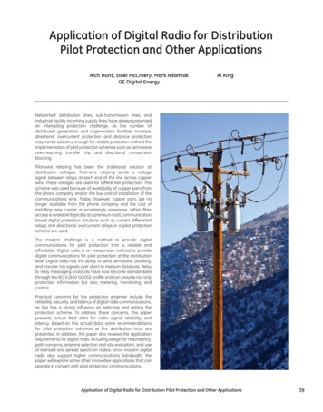
Machine Monitoring SystemsTransmission data Profibus DP:There are 5 analog, 13 binary and6 set/reset functions at disposal forthe output via the optional ProfibusDP.The following functions arepossible:Current speedScaled speedMachine accelerationMaximum speed-Direction of rotationControl inputs to reset individualSensor breaklatched messages and alarmSensor short-circuitoutputs as well as three controlGap – valueinputs to activate the test values.Switching state of functionoutputs 1 to 6The baud rates of the Profibus DPLive signal to indicate sub- data transmission is between 9600sequent electronic circuits that and 12000 KBit/s.the function of the electronic isOK.Test functions:To test the overspeed protectionsystem and the signal lines duringcommissioning in a way as simpleas possible, the speed monitors areequipped with a ramp test.The ramp test can be started andcontrolled via the configurationsoftware. The following parametershave to be entered for the test:- Start speed- End speed- Ramp time- Stop time- Analog output active or notThe ramps can be programmedfor increasing or decreasing runs.After the ramp test was started,the monitor runs from the startspeed up to the configured endspeed. When reaching the definedspeeds, the configured alarm limitswill switch and the current outputswill follow the predefined speedvalues (if activated).Safety logic:In case the ramp test is activatedwhen the machine is alreadyrunning, the safety logic checks,whether the machine speed is higherthan the predefined speed of theramp test. As long as the measuredspeed is higher than the simulatedspeed of the ramp test, the currentoutputs and the alarm outputs willreflect on the machine speed. Whenthe simulated speed of the ramp testhas exceeded the measured speed,the binary outputs and the analogoutput will show the state of thesimulated ramp speed.Dual current function:On activating this function, aselectable range, e.g. 0.300 rpm(see fig. 1) is output as currentrange 0/4.20 mA.When exceeding the limit of 300rpm, the module switches over andwill then output the completemeasuring range as current range0/4.20 mA.The switching between the twocurrent ranges is indicated via therelevant function output.Fig. 1 shows an example for adualcurrentoutputwith0.300.3000 rpm on a currentoutput 0.20 mA.When using this function with athree channel DOPS system, onlythe electrically isolated currentoutput IOUT1 should be used.Otherwise, analog error messages(with IOUT2) could arise whenswitching between the ranges.Iout20mA2mAn3003000Fig. 1Speed zoom function:By means of this function, acertain speed range to be definedwith start and end speed can bespread to the current output range0/4.20 mA.When using this function with athree channel DOPS system, onlythe electrically isolated currentoutput IOUT1 should be used.When using the current outputIOUT2, no analog comparison ofthe channels will be performedbelow the start value of the zoomrange.Fig. 2 shows an example for aspeed zoom with a range of 2750 to3250 rpm scaled on 4.20 00350020161284Fig. 2n275028502950305031503250Page 6 of 8
Machine Monitoring SystemsDisplay- and operating elements at the module front:One non-reactive output SENS 6 yellow LEDs:1 Mini DIN diode socket:(SMB socket):One LED for each of theRS232 interface for connection ofRange:0.4,1 Vppfunction- /limit valuesa computer for configuration and2 green LEDs: 10 kOhmdata interchange with the module.Load resistance:Internal resistance: 10 kOhmLED 1Supervision for the channel 1 SUB-D socket (9-pole).One non-reactive output PULSEFor connection of the Profibus DPassigned to this card(SMB socket):LED 2,3system cableRange:0.5 VIndication of the state of theLoad resistance: 10 kOhmtwo adjacent system chan- Handle:To pull out and insert the moduleInternal resistance: 5,1 kOhmnels. If one of the adjacentMMS 6350D/DPand for labelling purposes.channels fails (analog compa8-digit alphanumerical LEDrison), it will be indicated viamatrix, greenthe relevant LED.Power supply speed monitors:Redundant supply input via two Current consumption:supply inputs, decoupled viamax. approx. 250 mA per carddiodes.(with display and Profibus)Supply voltage: 18.24.32 VDCaccording to IEC 60654-2Other supply voltages can be realizedwithadditionalsystempowersupplies.Power consumption systemmax. 20 W(max. 840 mA at 24 V)Environmental conditions:Protection class:Module: IP 00 according toDIN 40050Front plate: IP21 according toDIN 40050Climatic conditions:according to DIN 40040 classKTFOperating temperature range:0. 55 C (131 F)max. 65 C (149 F)Temperature range for storageand transport:-40. 70 C (-40. 158 F)Permissible relative humidity:5.95%, non condensingPermissible vibration:according to IEC- 68-2 part 6Vibration amplitude:0.15 mm in range 10.55 HzReference temperature: 23 C (73,4 F)Vibration acceleration:219.6 m/s in range 55.150 HzPermissible shock:according to IEC- 68-2 part 29peak value of acceleration:298 m/snominal shock duration:16 msEMC resistance:according to EN 50081-1/EN50082-2Requirements on configuration PC:Configuration of modules is made Processor:via the RS 232 interface on thePentium II, 266 MHz or bettermodule front or via the RS 485 busby means of a computer (laptop) Interfaces:withthefollowingminimumOne free RS 232 interfacespecifications:Capacity of hard disk:min. 50 MBRequired working memory:min. 500 MB (in accordance withrequest of the operating system)Operating system: Windows 2000 and XPBackplane MMS 6351/x0:ScrewterminaladapterMMS 6361:Page 7 of 8
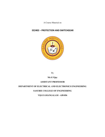
Machine Monitoring SystemsTrigger wheel and mounting angle of sensors:The more precise the triggerwheel has been fabricated, the moreexact the speed measurement canbe performed.PR 6423/.A tooth depth of at least 1 mm hasproved to be advantageous whenusing the PR 6423/. sensor with ameasuring range of 1 mm. With thistooth depth a continuous distancesupervision (Channel Clear) of thesensor is possible.The mounting angles of thesensors result from the geometricalspecification of the trigger wheel andthe minimum distances between thesensors.PR 6423/.These angles are important for acorrect detection of the signal pulsesand to detect the direction of rotation.--thetriggerRectangle 1 mm SensorModule of trigger wheel **PR 6422 2PR 6423 3PR 9376 1DistanceSensor - toothRadial run out:PR 6423/.Fig. 4 0.5.1 mm 0.05 mm** Module P[mm] / πMMS 6350/DPMMS 6350D/DPMMS 6351/00MMS 6351/10MMS 6352MMS 6360MMS 6362MMS 6363MMS 6361MMS 6950MMS 6354BLE 008Speed measurement card with PROFIBUS DP. 9100 – 00065Speed monitor with digital display and PROFIBUS DP . . 9100 – 00066Backplane for System DOPS. 9100 – 00047Backplane for System DOPS AS. 9100 – 0004919“ rack / 3HE . 9100 – 00053Connection cable 25 pol. SUB D 3 m. 9510 – 00006Connection cable 25 pol. SUB D 0,5 m. 9510 – 00015Profibus connection cable 4 m .9510 – 00024Screw terminal 25 pol. SUB D. 9100 – 00052Configuration Kit. 9510 – 00005Set of blind plates . 9501 – 00005Blind plate 8 TE . 9501 – 00003 epro GmbHJöbkesweg 3 D-48599 GronauTel. 49 (0) 2562/709-245Fax 49 (0) 2562/709-255Further information:Internet: www.epro.deE-Mail: info@epro.dePage 8 of 86010 – 00031 04/08 V1.03Order numbers:Printed in Germany. Due to continuous research and product development epro reserves the right to change the specificationwithout notice.Requirements onwheel:- Tooth form- Tooth depth- Tooth width
epro offers three system variants. System DOPS This system offers a maximum in functionality and is certified according to SIL3 - DIN EN 61508 in combination with epro MMS eddy current measuring chains. It requires the following components: - 3 x monitor MMS 6350 (/DP) (incl. firmware applic. no. 0) Profibus-interface (optional)