Transcription
View metadata, citation and similar papers at core.ac.ukbrought to you byCOREprovided by International Journal on Advanced Science, Engineering and Information TechnologyVol.7 (2017) No. 6ISSN: 2088-5334Implementation of Robot Operating System in Beaglebone Blackbased Mobile Robot for Obstacle Avoidance ApplicationMohamad Fauzi Zakaria#, Joo Chin Shing#, Mohd Razali Md Tomari##Advanced Mechatronics Research Group (AdMiRe) Faculty of Electrical and Electronic Engineering Universiti Tun Hussein Onn Malaysia(UTHM), 86400 Batu Pahat, Johor, MalaysiaE-mail: mfauzi@uthm.edu.my, franciscs125@gmail.com, mdrazali@uthm.edu.myAbstract— The Robot Operating System (ROS) is a collection of tools, libraries, and conventions that focus on simplifying the task ofcreating a complex and advanced robotics system. Its standard framework can be shared with another robotics system that has asimilar platform and suitable for being introduced as an educational tool in robotics. However, the problems found out in the currentrobot platform available in the market are expensive and encapsulated. The development of an open source robot platform isencouraged. Therefore, this research is carried out to design and develop an ROS based obstacle avoidance system for existingdifferential-wheeled mobile robot. The ROS was installed under Ubuntu 14.04 on a Beaglebone Black embedded computer system.Then, the ROS was implemented together with the obstacle avoidance system to establish the communication between programnodes. The mobile robot was then designed and developed to examine the obstacle avoidance application. The debugging process wascarried out to check the obstacle avoidance system application based on the communication between nodes. This process is importantin examining the message publishing and subscribing from all nodes. The obstacle avoidance mobile robot has been successfully testedwhere the communication between nodes was running without any problem.Keywords— robot operating system; differential-wheeled mobile robot; beaglebone black; obstacle avoidanceI. INTRODUCTIONMobile robotics in education is a pedagogical tool thatpromoting active learning and involve multi-disciplinaryknowledge [1], [2]. Educators in Science, Technology,Engineering and Math (STEM) frequently choose roboticssystem as a subject STEM-focused problem-based learning(PBL)[3]. Therefore, the ideal features of an educationalrobot for a group of students are a small physical size forminimum workspace area, low power consumption, highpower computational and modular configuration.Most mobile robotics systems have similar functionalitiesthat can be shared and used in other robots when using thesame standard software framework. The current frameworkwidely used is Robot Operating System (ROS). ROSprovides standard operating system facilities such mentation of commonly used functionalities, messagepassing between processes and package management [4], [5].It is based on graph architecture with a centralized topologywhere processing takes place in nodes that may receive orpost, such as multiplex sensor, actuator, control, state,planning, and navigation [6], [7].The current implementation of ROS in mobile roboticssystem is using a laptop computer integrated with an2213embedded controller. Their dimension is more than 30 cm x15 cm, consequently not suitable for academic purposeespecially when the testing area is limited [8]–[13].Therefore, there is a need a small size robot to be designedthat uses an embedded Linux single-board computer. Thisembedded Linux board is low power consumption and opensource in hardware and software capabilities which fulfil theideal features of the educational robot.The specific objectives of this paper are to implement theROS on embedded Linux system and to design and developan obstacle avoidance application for the differentialwheeled mobile robot. This robot would be a teaching toolfor a course of Mobile Robotics at the Faculty of Electricaland Electronic Engineering, Universiti Tun Hussein OnnMalaysia. This course covers robot perception, localization,planning and navigation that would be relied on thesuccessful projects done by ROS community.II. MATERIAL AND METHODThe mobile robot is a differential wheeled configurationthat developed based on 2WD miniQ robot chassis. Thechassis diameter is 12.2 cm, and the wheel diameter is 4.2cm. Two DC micro gear motors are used for the movementof the robot. An Infrared rangefinder sensor is used to detectthe obstacle in front to stop the robot from moving. A servo
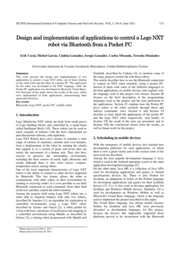
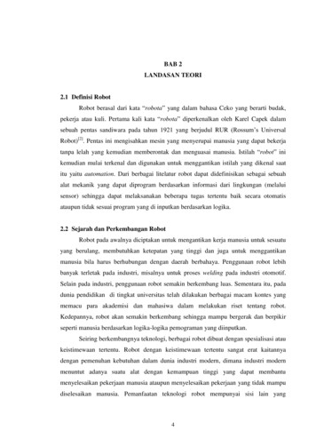
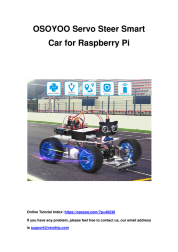
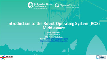
motor is attached to the infrared sensor to detect the obstaclein three angles. (45 , 90 , and 135 ). The main controllerboard is a Beaglebone Black Revision C, and its baseoperating system is Ubuntu ARM 14.04 LTS. Under thisoperating system, the ROS Jade version is installed.A. System ArchitectureThe overall system architecture of this research is shownin Fig. 1. This system consists of three major applicationsthat are obstacle avoidance system and motor control system.The obstacle avoidance system will continuously receivedata from the infrared sensor and servo motor. These datawill further be processed by the obstacle avoidancealgorithm. After that, the processed information will betransferred to the motor control system to trigger the dcmotors to turn to the desired direction. The motor controlsystem is implemented to move the robot by trigger the DCmotor in the forward direction or left, and right directiondepends on the obstacle detected. ifconfig eth1 192.168.7.1 iptables –table nat –append POSTROUTING –outinterface wlan0 –j MASQUERADE iptables –append FORWARD –in-interface eth1 –jACCEPT echo 1 /proc/sys/net/ipv4/ip forwardFig. 1 Block diagram of system architectureB. HardwareFig. 2 shows the circuit connection of the electronicshardware interface. The infrared sensor that attached to RCServo Motor is connected to an analog pin, AIN0 ofBeaglebone Black. The position control of Servo Motor isbased on pulse width modulation (PWM) signal from pinP9-P13. The Beaglebone Black control the speed anddirection of two DC motors via an L293D motor driver. Thepower supply system has relied on a 5VDC power bankbattery with maximum 2A current.C. ROS Installation on Beaglebone BlackThe Beaglebone Black is communicated through SecureShell (SSH) in a Linux system. The command to access SSHis: ssh ubuntu@192.168.7.2After that, the system will prompt the user to enter theusername and password. The default username is ubuntu,and the default password is temppwd. In order to install ROSon Beaglebone Black, the network access is necessary. Thenetwork of main OS can be shared with the OS onBeaglebone Black with the following command:On the Beaglebone Black:Fig. 2 Schematic diagram of electronics circuit sudo ifconfig usb0 192.168.7.2 sudo route add default gw 192.168.7.1The following installation guideline is based on [6].Step 1:Before the installation of ROS, the system locale needs to beset with the command:On the main OS:#wlan0 is the main OS internet facing interface, eth1 is theBeaglebone USB connection. sudo su2214
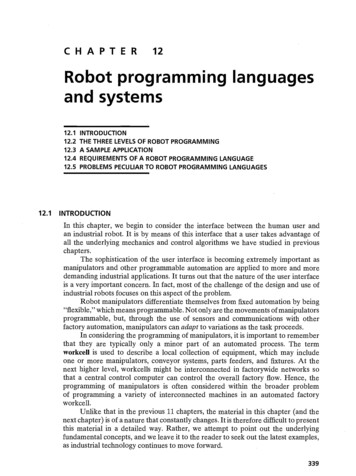
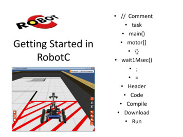
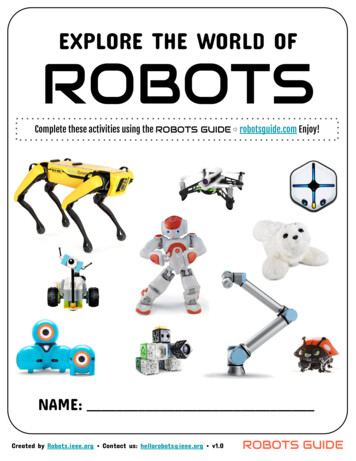
will stop moving, and the servo motor will turn to 0 and180 to detect the distance at 0 and 180 . If the distance at0 is more than the distance at 180 , the motor will turn tothe right (0 ). On the other hand, the motor will turn to theleft (180 ) if the distance at 180 is more than the distance at0 . If the distance at left and right is less than 30cm, therobot will turn backward. After that, the robot will continueto move in the forward direction until an obstacle is detected.In Fig. 4, the motor control node consists of a programthat is used to control the rotation direction of the motor.This node will continuously subscribe to the stop movingmessage and turn direction message from the sensor nodeand compare distance node. Normally, if no obstacle isdetected, the motor control node will control the rotation ofthe motor in the forward direction. If the stop movingmessage is received means obstacle is detected, the motorswill be stopped from rotating to stop the robot from moving.If turn direction message is received, motors are triggeredto move the robot in left or right direction depends on themessage received. After the robot finished the move in adirection, the motor control node will then control therotation of the motor to rotate in the forward direction. Tostart with, the node should register with the ROS Master tolocate the message passing path to the destination node. sudo update-locale LANG C LANGUAGE C LC ALL CLC MESSAGES POSIXStep 2:The sources.list is set up with the following command toaccept software from ARM mirror on packages.ros.org: sudo sh –c ‘echo “deb http://packages.ros.org/ros/ubuntutrusty main” /etc/apt/sources.list.d/ros-latest.list’Step 3:Set up the keys with the command: o/master/ros.key -O - sudo apt-key add –Step 4:The ROS packages is installed with the following command: sudo apt-get install ros-indgo-ros-baseStep 5:rosdep need to be installed first to enable the installation ofsystem dependencies with the command: sudo apt-get install python-rosdep sudo rosdep init rosdep updateStep 6:The ROS environment is setup with the command: echo “source /opt/ros/indigo/setup.bash” /.bashrc source /.bashrcStep 7:Finally, after all, the requirements are set up, the ROS can beinstalled with the following command: sudo apt-get install python-rosintallD. ROS System SetupFirst, a workspace is created as the project folder of ROS.In ROS, the developer standardizes the project folder ofROS as catkin workspace. The user can create the catkinworkspace with the following command: mkdir –p /catkin ws/src cd /catkin ws/src catkin init workspaceAfter the workspace is created, it must be built first to insertthe project folder into ROS system. This can be enabled bythe following command: cd /catkin ws/ catkin makeE. Application SoftwareThe programming language for software development isin Python. Before the coding was written, the overallsoftware flow-chart should be designed. As in Fig. 3, oncethe program is running, the robot will start moving in aforward direction when no obstacle is detected. The infraredsensor attached to the servo motor will repeatedly detect thedistance in front from angle 90 45 90 135 . Whenthe distance of obstacle detected is less than 15 cm, the robotFig. 3 Obstacle-avoidance software flow-chart2215
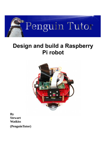
turn right message is published. Otherwise, a turn leftmessage is sent. Fig. 7 shows the block diagram for comparedistance node.Fig. 4 Motor control systemThe sensor node continuously receives data from theinfrared sensor and the data received is converted intocentimeter to indicate the distance detected in the currentmoment as shown in Fig. 5. The sensor node is alwayssubscribed to the check message. When the check messageis received, the sensor node will run the program to detectthe distance obstacle in front. The distance detected ispublished as a distance detected message to the servo motornode. The distance detected message will be subscribed byservo motor node to receive current distance detected by therobot; this data will be further processed by servo motornode.Fig. 6 Servomotor block diagramFig. 7 Compare distance block diagramFig. 5 Infra-red sensor block diagramIII. RESULT AND DISCUSSIONThe implementation of ROS in obstacle avoidancesystem is debugged based on the communication betweennodes. In a ROS system, many nodes are communicatingwith each other for an application. roscore is a collection ofnodes and programs that are pre-requisites of a ROS system.To enable communication of all the nodes, roscore must belaunched. Once the roscore is launched, it will start up: aROS Master; a ROS Parameter Server; and a rosout loggingnode. All the systems above are required to start up thecommunication between nodes. It can be terminated withkeyboard interrupt to shut down the ROS system.In Fig. 6, the servo motor node is responsible for controlthe motion of servo motor. This node will always subscribeto the distance detected topic. Due to the limitation of theinfrared sensor that is unable to detect object notperpendicular to the sensor, thus the servo motor is usedtogether with the sensor. The sensor will always check thedistance in front from the distance detected topic in 45 to135 with the use of servo motor; once an obstacle isdetected, the sensor will check the distance of left and right.The distance detected in the direction of left and right is thenpublished to compare distance node as a distance rightmessage and distance left message. Then compare distancenode will further process these two messages to decidewhich direction to be moved to. Moreover, this node willalso publish an obstacle detected message when an obstacleis detected in front.The compare distance node is constructed to compare thedistance at 0 and 180 . This node is continuouslysubscribed to two messages, distance left message anddistance right message. Two of this message is sent byservo motor node when an obstacle is detected. Themessages received are the distance detected at 0 and 180 which is an Int16 data type. The program of comparedistance node will compare the distance received andpublish a message called direction to DC motor node. If thedistance at 180 is more than the distance at 0 , theA. ROS GraphThe ROS graph provides a visualization graph for theROS computation graph. It is used to visualize thecommunication between different nodes [14]. Each of thenodes initializes a specific topic to communicate with thespecific node. As a result, the sensor node initialized a topiccalled distance detect; this topic was subscribed by servomotor node by connecting to the same topic. This means thatonce the topic is subscribed by a node, communication canbe stabilized by publishing and subscribing to a message.2216
Fig. 8 ROS graphFig. 8 shows the ROS graph for communication betweenfour nodes. The topic distance detect is initialized by sensornode and subscribed by servo motor node to detect theobstacle distance. Besides, the servo motor initializing threetopics call dist detect right, dist detect left, and dist detect.The topics of dist detect right and dist detect left aresubscribed by compare distance node to compare thedistance of left and right, and then publish a message to DCmotor by through direction topic. Whereas, the dist detecttopic is subscribed by DC motor node to stop the robot frommoving. The DC motor node also initializes a topic calledforward to publish a move message to servo motor node.B. Execution of ROS NodesIn a ROS system, many nodes are communicating witheach other for an application. roscore is a collection of nodesand programs that are pre-requisites of a ROS system. Toenable communication of all the nodes, roscore must belaunched. Once the roscore is launched, it will start up: a ROS Master a ROS Parameter Server a rosout logging nodeFig. 10 Execution of roscoreC. Execution of Application NodesAfter the roscore is launched, the application’s programcan be run by using rosrun command. In a ROS system, theprogram is called as a node. Most of the nodes in ROSsystem are required to communicate with another node tosend and receive a message at that instance. Thus, all thenodes must be run so that all the features of an applicationcan be executed. The command to run the program is:In terminal 1: rosrun ultra class ultra class.pyAll the systems above are required to start up thecommunication between nodes. It can be terminated withkeyboard interrupt to shut down the ROS system. Beforerunning a roscore, the ROS must be source first to enable theaccess to the ROS commands and build into the workspace:In terminal 2: rosrun servo class servo class.py cd /catkin workspace source /opt/ros/jade/setup.bash source devel/setup.bashIn terminal 3: rosrun compare distance compare distance.pyFig. 9 and 10 show the source and roscore are run in theterminal.In terminal 4: rosrun dc motor dc motor.pyThe sensor node and servo motor needed to be executedtogether to establish the communication between these twoFig. 9 Source of ROS setup bash file2217
nodes. When the sensor node was executed, the programwould not be run if the servo motor node was not executed.This is because the sensor node was always waiting for themessage from the servo motor to detect the distance.Once the servo motor was executed, communication wasestablished, message publishing and subscribing wereinitiated. The programs of the sensor node and servo motornode would be executed. Figs. 11 and 12 show thecommunication between the sensor node and servo motornode.Moreover, compare distance node, and DC motor nodecould be executed after the sensor node, and servo motornode was executed. The compare distance node wouldalways wait for the message published by a servo motor.Thus, the program of this node would not be run if the servomotor node was not executed. Once the compare distancenode received a message from servo motor node, thedirection message would be published after the distancereceived was compared. Thus, the DC motor node wouldcontrol the DC motors depended on the message receivedfrom compare distance node. Figs. 13 and 14 show thecommunication between compare distance node and DCmotor node. The complete prototype of mobile robot systemwas successfully built and tested as shown in Fig. 15.Fig. 14 Execution of DC motor nodeFig. 15 Side view of complete prototypeIV. CONCLUSIONSAs a conclusion, Robot Operating System (ROS) is asystem designed for the development of a robotic system.The system is an open source where the robotic researchersor engineers can share their idea or system to the public interms of source code, system design or hardware design.Moreover, the information shared was kept on maintained bythe engineer which the engineer will continuously updatetheir system. The objective of the research is achieved byintegrating the ROS on the mobile robot designed. Theobstacle avoidance mobile robot is successfully designedbased on the ROS where the communication between theprograms is successfully integrated. Besides, the performanceof the robot is fast and smooth which the delay ofcommunication between programs is approximately in amillisecond. Thus, the Beaglebone Black based mobile robotthat equipped with ROS is recommended as a teaching toolfor mobile robotics course.Some improvement could be made in the future. Thepossible improvement found out is to reduce the wobblingduring navigation. Thus, two encoders are recommended toattach with DC motors for the implementation ofproportional, integral, and differential (PID) control system.With PID control system, the speed of the two DC motorscan be altered to obtain the same speed in both DC motors.Another possible improvement of the mobile robot is todetect a small and thin object due to the limitation ofdetection on the infrared sensor. Implementation of visiontechnique can solve this limitation to detect the small andFig. 11 Execution of sensor nodeFig. 12 Execution of servomotor nodeFig. 13 Execution of distance comparison node2218
thin object. Thus, a webcam is attached to the mobile robotso that the current image can be processed by a visionsystem.[6]ACKNOWLEDGMENT[8]The authors would like to thank the Office of Research,Innovation, Commercialization and Consultancy (ORICC),Universiti Tun Hussein Onn Malaysia (UTHM) for thefunding of this paper publication.[9]REFERENCES[10][1][2][3][4][5][7]S. F. R. Alves, H. F. Filho, R. Pegoraro, M. A. C. Caldeira, J. M.Rosário, and W. M. Yonezawa, “Proposal of educationalenvironments with mobile robots,” in 2011 IEEE 5th InternationalConference on Robotics, Automation and Mechatronics (RAM), 2011,pp. 264–269.M. Beschi, R. Adamini, A. Marini, and A. Visioli, “Using of theRobotic Operating System for PID control education,” IFAC-Pap.,vol. 48, no. 29, pp. 87–92, Jan. 2015.C. Vandevelde, F. Wyffels, M.-C. Ciocci, B. Vanderborght, and J.Saldien, “Design and evaluation of a DIY construction system foreducational robot kits,” Int. J. Technol. Des. Educ., vol. 26, no. 4, pp.521–540, Nov. 2016.“About ROS.” [Online]. Available: http://www.ros.org/about-ros/.[Accessed: 26-Mar-2017].A. Koubaa, Robot Operating System (ROS): The Complete Reference.Springer, 2016.[11][12][13][14]2219Enrique Fernández, L. Sánchez Crespo, A. Mahtani, and A. Martinez,Learning ROS for Robotics Programming. Packt Publishing Ltd,2015.L. Garber, “Robot OS: A New Day for Robot Design,” Computer,vol. 46, no. 12, pp. 16–20, Dec. 2013.E. Ruiz, R. Acuña, N. Certad, A. Terrones, and M. E. Cabrera,“Development of a Control Platform for the Mobile Robot RoombaUsing ROS and a Kinect Sensor,” in 2013 Latin American RoboticsSymposium and Competition, 2013, pp. 55–60.E. M. H. Zahugi, A. M. Shabani, and T. V. Prasad, “Libot: Design ofa low cost mobile robot for outdoor swarm robotics,” in 2012 IEEEInternational Conference on Cyber Technology in Automation,Control, and Intelligent Systems (CYBER), 2012, pp. 342–347.V. Bayar, B. Akar, U. Yayan, H. S. Yavuz, and A. Yazici, “Fuzzylogic based design of classical behaviors for mobile robots in ROSmiddleware,” in 2014 IEEE International Symposium on Innovationsin Intelligent Systems and Applications (INISTA) Proceedings, 2014,pp. 162–169.A. Araújo, D. Portugal, M. S. Couceiro, and R. P. Rocha,“Integrating Arduino-Based Educational Mobile Robots in ROS,” J.Intell. Robot. Syst., pp. 1–18, Feb. 2014.G. Fu and X. Zhang, “ROSBOT: A low-cost autonomous socialrobot,” in 2015 IEEE International Conference on AdvancedIntelligent Mechatronics (AIM), 2015, pp. 1789–1794.H. I. M. A. Omara and K. S. M. Sahari, “Indoor mapping usingkinect and ROS,” in 2015 International Symposium on Agents, MultiAgent Systems and Robotics (ISAMSR), 2015, pp. 110–116.M. Quigley, B. Gerkey, and W. D. Smart, Programming Robots withROS: A Practical Introduction to the Robot Operating System.O’Reilly Media, Inc., 2015.
on Beaglebone Black, the network access is necessary. The network of main OS can be shared with the OS on Beaglebone Black with the following command: On the Beaglebone Black: sudo ifconfig usb0 192.168.7.2 sudo route add default gw 192.168.7.1 On the main OS: #wlan0 is the main OS internet facing interface, eth1 is the Beaglebone USB .