Transcription
Design and build a RaspberryPi robotByStewartWatkiss(PenguinTutor)
About this guideThis is a guide to creating Ruby Robot. An inexpensive robot vehicle controlled by a Raspberry Picomputer.CopyrightThis guide is provided through a creative commons license - Attribution-ShareAlike 3.0 Unported.License details: t the authorStewart Watkiss graduated from The University of Hull, UK, with a masters degree in electronicengineering. Since then he has been working in the IT industry, including Linux and networking.Linux has been his passion for many years and he has gained certification at LPIC-2. He runs thewebsite PenguinTutor.com providing information on learning Linux, electronics and the RaspberryPi. After working on several projects with the Raspberry Pi, both on his own or with his children, hesigned up as a STEM ambassador to pass some of his knowledge on to school children helping outat local schools.He has also been technical reviewer of the book “Learning Raspberry Pi with Linux”, published byApress, and a volunteer guest writer for The MagPi free magazine.
DRAFT VersionContentsTable of ContentsContents.1Introduction.3How to use this guide.3Knowledge required.4Design decisions.4Creating a design specification.4Design specification for robot vehicle.5Deciding on main components.5Magician chassis kit.7Raspberry Pi.8Raspbian Linux operating system.9Initial configuration of the Raspberry Pi.10Download the NOOBS image.10Connect the Raspberry Pi for first time install.11A basic introduction to the Linux command line.13Connect the robot to an existing Wi-Fi network.15Installing additional software on Linux.16Create a Wi-Fi hotspot for the Raspberry Pi.17Check the dongle supports Wireless Access Point mode.17Configure the static IP address.18Configure the DHCP server.18Configure the Wireless Access Point software.20Logging on to the Raspberry Pi using SSH.21Adding the Raspberry Pi to the robot chassis.25Power for the Raspberry Pi and motors.25Shared or separate power supplies.26Pre-supplied power supply.27Connecting the power.27Connecting the breadboard to the Raspberry Pi GPIO.27Electronic circuit.30H-Bridge motor controller.30H-Bridge using relays / transistors / FETS / ICs.32SN754410 quad half-H driver IC.33GPIO ports.35Circuit diagram.37Breadboard design.38Creating a more permanent circuit (stripboard vs PCB).40Printed Circuit Board - RyanTeck PCB kit RTK-000-001.40With diodes or without diodes.42Heatsink.43Controlling the speed of the motors with PWM.43Writing the software to make it work.441
DRAFT VersionBasic software design points.45Using the design to provide implementation details.45Choosing the programming language.46Getting started with Python.46Learning to program in Python.49Programming the GPIO with Python.50Remote control Python program.51Testing the robot.53Adding a camera.53Using the camera.55Developing the robot vehicle further.56Remote control vs. autonomous robots.56Adding additional sensors.57What is I2C and SPI?.57What's next?.58Appendix A – Shopping list.59Appendix B – Software requirements specification.60Software requirements specification for Ruby Robot v1.60Appendix C – Program listing robotcontrol.py.62Appendix D – Key codes for remote control program.65Glossary.662
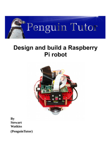
DRAFT VersionIntroductionThis project is designed as a way of learning physical computing (the combination of computerprogramming with electronic circuits) in a fun way.When first starting out with electronics then getting a LED to flash can be quite exciting, andgetting it to respond to programming done on a computer is another big leap, but once you havemastered those skills then it can be easy to lose interest. What we need is something that is exciting,fun to make, something you can show off to friends. The next challenge is that it needs to beaffordable. It needs to be within a reasonable price that children (or their parents) can pay for aneducational toy; unfortunately for most of us this rules out Lego Mindstorms and many commercialrobots.I therefore started looking for an inexpensive robot vehicle kit that could be used for others learningabout robotics. The result was the Ruby Robot shown on the front cover. The reactions I have hadwhen taking the robot out in public has shown that children do indeed get excited when they see arobot, especially when you let them have a go at controlling it using a mobile phone or tablet.This guide is a detailed guide intended for young makers, teachers, computing or STEM clubleaders, or parents.How to use this guideThe guide is designed to be worked through page by page following the instructions on your ownRaspberry Pi and robot chassis. The commands are shown with a grey background that should beentered in to the Raspberry Pi, or that represent what the completed code should look like. Youshould also consider the different options highlighted (see the chapter on Design decisions) foropportunities to personalise your own robot vehicle.If you are already familiar with a particular topic or are more interested in other parts then it is fineto skip that section or to just focus on the actions in that section.At the end you will have a robot vehicle which is similar to the one described, but with your ownpersonal characteristics. Hopefully you will also learn about the various aspects involved in thedesign and build of the robot and most importantly have fun in doing it.If you are going to create the robot then you are going to need some parts. I've created a parts list inAppendix A which should be enough to get started. You may want to add other things later, but thisis enough to be starting with.3
DRAFT VersionKnowledge requiredThis project is designed for secondary school children or those studying further education. Somebasic knowledge of the Raspberry Pi will be useful (http://www.penguintutor.com/raspberrypi/) orsome experience of running Linux and the command line interface on another computer. I haveincluded some more links to related websites within this guide, or you could learn from a Linux orRaspberry Pi book such as Learn Linux with Raspberry Pi published by Apress or through theMagPi magazine (http://www.themagpi.com/) . A very basic understanding of electronic circuittheory would also be useful. More advanced topics are explained in detail in this guide.An understanding of Python programming would also be an advantage. You don't need to knowPython programming to create the robot, although will help with understanding the code works. Youwill need to know some programming if you want to make most of the suggested improvements soit is worth taking the time to learn Python.The robot can also be a used with younger children by skipping some of the theory and justconfiguring as per the guide. For example it is possible to build the robot and then program itwithout needing to understand any of the electronic circuitry.Design decisionsWhilst it's possible to follow the exact same design as I put down here there are lots of opportunitiesto do things differently. The design of the robot should become part of the learning experience. Thisallows the designer, or engineer to use the correct term, to create a unique robot that is individual tothem and perhaps one that is more appropriate to specific tasks.One of the reasons for using the magician robot chassis is that this is a versatile base that allowscomponents to be mounted in any number of different ways. This allows a unique robot to becreated. Some of the things to consider are direction of the robot, and the position of the RaspberryPi, the electronic circuit and the batteries. There are no right and wrong ways to locate these, butthere are often pros and cons depending upon the specific use. Some of these advantages anddisadvantages may not become apparent until later in the project, but this is all part of the learningexperience.I will explain some of the pros and cons in the relevant sections. Look out for the lightbulb sign as an opportunity to customise the design.Creating a design specificationBefore starting on any project then you need to know what you are going to make. This may seemobvious, but turning this into a written specification can help with decisions that need to be made4
DRAFT Versionlater on. The design specification should describe the aims of the project rather than the actual partsand devices to be used. You may already have an idea of how you will make the project, but as youlist the specification you may think of other ideas. There is no need to include the software design atthis stage, that will be covered later.The amount of detail you include in the design specification will depend upon the complexity of theproject and who the intended audience is. If it's just for a simple project for a hobby then you cankeep it fairly brief, but if you are going to be asking for someone to fund your project or will beproviding a write-up as part of a school or college project then you may need to provide a moredetailed specification. I have created a simple design specification for this project as it's an informalproject that I created for myself. I have started with a brief summary and then provided a list ofrequirements. In some cases I have given some flexibility within the requirements (such as referringto a computing devices rather than a specific computer or model of phone that it should becontrolled by), whereas some are more specific (such as maximum budget). Each specificationshould be something that can be tested to test that it is met. Most of the specification is mandatory,but I have also included a “nice to have” feature.Design specification for robot vehicleThis aim of the project is to create a robot vehicle that can be controlled from a computer or mobilephone. This is being made as a fun project that can help demonstrate the principles involved indesigning and building a project. The vehicle should be relatively cheap and simple to build so thatit can be replicated by a school or college student. It should be simple to make using tools available in a standard workshop. Vehicle should be able to move around on an even floor (such as carpet or wooden floor). It should be possible to control the vehicle using a computer or other computing device. Maximum cost is 100 (excluding batteries and optional camera). It should be able to have a camera mounted to take photos of the environment. Live view or video recording would be an advantage (not required). It should provide some flexibility for adding additional features. It should be self powered. Communication should be wireless so that no cables are required connecting to the vehicle. The vehicle should be small enough so that it can be taken to events to give demonstrations.Deciding on main componentsThe decision for the main components can now be made based upon whether they meet thespecification. Although all the factors were considered the two main requirements for determining5
DRAFT Versionthe main components were cost and that is should be simple to make with standard tools.Whilst I haven't included a list of available tools within the specification I have referred to toolsused in a standard workshop, which means that standard screwdriver may be required, but it shouldnot require a laser cutter or 3D printer which whilst becoming more popular is not found in yourtypical workshop. There is potentially a grey area in between, such as whether a solder iron isavailable, which is an example of something you may need to clarify when working on a design.You may need to go back to the project sponsor to ask them to confirm whether it is required (whichin the case of a hobby project may be yourself). As you will see later for this project a soldering ironis not actually required although it can be useful, particularly when looking at expanding the projectin future.Without a laser cutter then this is going to mean using a robot kit or creating one from hobbycomponents. Of course if you do have access to some more specialist tools then you have moreflexibility in your design which would allow you to make a truly custom robot.The two main components that were decided upon were the Magician Robot Chassis for the bodyand wheels, with a Raspberry Pi to control it.Before finalising the design it is a good idea to consider alternatives. I was not able to find analternative robot chassis that would fit in with the specification (mainly because of the cost aspect),although since starting there are some clones of the magician robot and at the time of writing thereis a simpler single layer design looking for funding through Indiegogo. I also considered an Arduinocompared with a Raspberry Pi for the processor. The decision to use the Raspberry Pi came down tosupporting wireless control (it is possible with Arduino, but adds significant additional cost) andthat programming a Raspberry Pi is generally considered easier than programming an Arduino.Having decided on the Raspberry Pi another decision to be made was what wireless method to use.The two most common ways of communicating using wireless are Wi-Fi (wireless networking) orBluetooth. Neither of these are included in the Raspberry Pi, but can be added easily with a low costUSB adapter. Wi-Fi was chosen because of it's flexibility (it can also be used to configure theRaspberry Pi) and flexibility for sending images from the camera.In use I have found one disadvantage to using Wi-Fi, which is that it is prone to interference fromother Wi-Fi networks. The robot uses a small USB dongle which does not have the signal strengthto compete with strong wireless access points (WAP) if they are in the same room. I found that I hadto keep the tablet I was connecting with close to the robot if it was using the same channel as anearby WAP. The Wi-Fi configuration can be changed to use a different channel, which may need tobe changed when taking the robot to a different site.More detailed decisions needed to be made later on in the design process, but having decided onthis main components made the remaining decisions easier later on.6
DRAFT VersionMagician chassis kitThe magician chassis is a commercial robot vehicle kit available from several electronic and robotsuppliers. The chassis appears to have been created with the Arduino in mind as the powerconnector from the battery pack matches with the Arduino power supply. This is something we willaddress later when we look at connecting the power supply to the Raspberry Pi.Instructions for assembling the kit are provided and are fairly easy to follow. When complete itshould look like the photo below.If you follow the instructions provided with the magician robot chassis then the batteryholder will be installed on the lower platform. The advantage of this is that it leavesplenty of space on the top to create the electronic circuits, but does mean having tounscrew the top of the robot chassis to be able to change the battery. You may prefer tohave the battery on the top of the chassis so it is easier to swap batteries. An alternative is to swapthe batteries for a rechargeable unit that can be charged when installed on the robot; this willhowever increase the cost so it has not been considered at this stage. For now I suggest you installthe batteries on the bottom so that it is easier to create / modify the electronic circuit on the top ofthe chassis.Looking at the underside we can see how the robot vehicle will move around. There are two maindrives wheels each of which is connected to it's own motor. There is then caster which is effectivelya large ball-bearing which can move in any direction.Note that there are two discs on the motor shafts. These are not used at the moment, but are usefulfor being able to determine how far the vehicle has travelled. We will look at this later in the guide,for now take care not to lose these discs.7
DRAFT VersionNow is a good idea to decide which direction is forward. The motors can be driven ineither direction controlled by the electronic circuit and whilst there are advantages tohaving the driving wheels towards the front, particularly when travelling uphill, themotors provided are not going to be able to climb more than a very gentle slope so thisis not much of an issue. In my initial version of the robot I have chosen the square end with thecaster as the front, as the Raspberry Pi camera mount fits well on the straight edge. If you arelooking to install sensors to determine if the robot reaches a wall you may instead prefer to use thecurved edge as the front as there are more holes and space for mounting other sensors. If youchange your mind then it's only a software change and it can drive in the opposite direction, butmoving the position of the camera and Raspberry Pi is a little harder later.Raspberry PiThe robot chassis appears to have been designed for use with the Arduino, which is an open sourceprogrammable controller. Whilst the Arduino can control the motors and make simple decisionsbased on input sensors it does not have the processing capability as the Raspberry Pi, which is whatwe are using in this project. The Raspberry Pi is a small low cost computer designed specifically foreducation. It is based around an ARM processor which can run the open source Linux operatingsystem and includes a GPIO (General Purpose Input Output) connector which can be used tointerface to electronic circuits that can control the robot. The Raspberry Pi can also be connected toa camera which gives the robot the ability to see it's surroundings, or can be used to send imagesback to the operator.There are currently two different models of the Raspberry Pi. The model A is more basic with onlyone USB port, no wired Ethernet port and only 256Mb of memory, the model B includes additionalfeatures including an additional USB port, ethernet port and an increase to the amount of memory to512MB. The model A is also less expensive.8
DRAFT VersionThe Raspberry Pi model A is recommended for this project as we won't be using a wired Ethernetport and the model A uses less power than the model B. The fact that the model A uses less power isuseful when running on batteries. It can still run on a Raspberry Pi model B if you have one already,but you may need to consider a different power supply (see later).It's not possible for the Raspberry Pi to control the motors directly, so we are also going to need anelectronic circuit. When designing a circuit it's a good idea to start by using a prototypingbreadboard so we'll be adding a breadboard onto the robot chassis.The Raspberry Pi and breadboard can be installed in various different positions on therobot chassis. These can be installed on either the top or bottom plates of the chassis.For now I recommend using the top layer for the breadboard as it will make it easier tomake any changes to the electronic circuit.You will need to consider the length of the cables required as well as any connectors on theRaspberry Pi that you would like to connect to. For example the camera comes with only a shortribbon cable to connect it to the Raspberry Pi, which is the reason I placed the Raspberry Pi close tothe camera. I also put the Raspberry Pi with the GPIO connector closest to the breadboard so thatonly a short lead is required to connect to the breadboard. If you are going to be using a Wi-Fidongle you need to ensure there is space near the USB ports for the dongle (such as by having theUSB port point towards the side or the chassis) and if you want to add a speaker (so the robot canspeak) then you should ensure that there is space by the 3.5mm audio socket to plug in a speakercable. Finally whilst you won't be connecting the robot directly to a TV or monitor when it's in useit may be a good idea to leave space near the HDMI connector to be able to connect a screen whendoing the initial set-up. Access to the HDMI port is not actually required as the set-up can be doneon a different Raspberry Pi / computer or the Raspberry Pi could be temporarily disconnected whena new image is created.Raspbian Linux operating systemThe recommended operating system to run on the Raspberry Pi is Raspbian Linux. This is adistribution specifically created for the Raspberry Pi based upon Debian Linux. It can be purchasedpre-installed on a SD card from the main suppliers (look for recent version of NOOBs SD cards), orcan be downloaded from the Raspberry Pi website for install onto an SD cardhttp://www.raspberrypi.org/downloads .Linux is a free open source operating system. It is free for anyone to use and its source code isavailable. Much of the software within the distribution is provided under the GPL (GNU GeneralPublic License) which means that if you modify and share the code then you need to make yourmodifications available under the same conditions.If you are familiar with other operating systems such as Windows, then you will find the Linuxgraphical desktop (sometimes referred to as a GUI – Graphical User Interface) familiar. It has a9
DRAFT Versionlook and feel more reminiscent of older versions, which is due to the low specification processorneeding a leaner operating system. Modern Linux distributions running on a powerful computerprovide a more feature rich experience.One thing that is different to some other operating systems is that you can run the full operatingsystem without needing to have a graphical environment loaded and you can run commands on thecomputer remotely using the command line. This may be a little strange for those used to clickingon icons, but provides a lot of control and is very powerful. It is particularly useful in projects suchas this robot where we can control and program the robot without needing to connect it to a monitoror TV.It may be useful to spend some time getting familiar with Linux before embarking on the rest of thisproject. To find out more about the Linux operating system seehttp://www.penguintutor.com/linux/about-linux or one of the many guides on Linux or theRaspberry Pi.Initial configuration of the Raspberry PiWe will need to make some configuration changes to the Raspberry Pi configuration to allow us touse certain features.Download the NOOBS imageIn this section we will set-up the Raspberry Pi with the Raspbian operating system. If you arealready familiar with the Raspberry Pi and have set-up the operating system then you can skip thissection, but ensure you read the section on creating a Wi-Fi hotspot if you would like to be able tocontrol the robot outside of the range of your home wireless network.For this project we will be using the Raspbian operating system. This is easiest to install using theNOOBS software image. You can purchase an SD card with the operating system pre-loaded or youcan download the software for free and install it onto a standard SD card. I assume you have anexisting SD card and will be downloading the image from the Internet.You will need a 4GB SD card (or micro-SD card in an SD adapter). If it is a new pre-formatted cardthen you should be able to use it as it is, but otherwise you should format the card using the SD cardassociation's formatting tool: https://www.sdcard.org/downloads/formatter 4/Formatting the card and running the NOOBs initial configuration will delete allthe data on the SD card. Make sure you have made a copy of any data you want tokeep before formatting the card.10
DRAFT VersionDownload the NOOBS image from the Raspberry Pi website:http://www.raspberrypi.org/downloadsYou need to select the standard NOOBS image rather than the Lite version (especially if you areusing a model A which has no
The result was the Ruby Robot shown on the front cover. The reactions I have had when taking the robot out in public has shown that children do indeed get excited when they see a robot, especially when you let them ha