Transcription
WarmWire Installation ManualSeriesWB & WRPlease be aware local codes may require this product and/or the thermostatic controlto be installed or connected by an electrician.
Read this Manual BEFORE using this equipment.Failure to read and follow all safety and use information can resultin death, serious personal injury, property damage, or damageto the equipment.Keep this Manual for future reference.WarmWire is a simple, economical way to warm any floor, and provide years of lasting comfort. Thisinstruction manual provides complete details, suggestions, and safety precautions for installing thisfloor-warming system. Fasten the cables to the floor. Then, depending on the floor coverings to beused, put down a layer of thin-set, thick-set, or self-leveling mortar on top of the cables. Finally, installthe floor coverings. It’s that simple!Specifications for WarmWire:WarmWire is a complete heating cable consisting of a series resistance heating cable and apower lead for connection to the electric power supply. The heating cable cannot be cut to fit.Voltages: 120 VAC, 240 VAC, 1-phaseWatts: 3 W/linear foot. Approximately 10.3 W/ft2 (34 Btu/h/ft2) for 3.5" spacing, 12 W/ft2(41 Btu/h/ft2) for 3" spacing. and 14.4 W/ft2 (51 Btu/h/ft2) for 2.5" spacing. (See Table 2)2.5" spacing may only be used under masonry surfaces with a maximum floor covering R-valueof R-1.5 as indicated in this manual. 3" or 3.5" spacing may be used under floor covering typeswith a maximum R-value of R-2.5.Maximum circuit load: 15 ampsMaximum circuit overload protection: 20 amp breakerGFCI: (Ground Fault Circuit Interrupter) required for each circuit (included in the SunStat control)Listing: UL Listed for U.S. and Canada under UL 1673 and CAN/CSA C22.2 No. 130.2-93,File No. E185866Application: Indoor floor heating only (-X on the nameplate label indicates CUL Listing for thisapplication). Suitable for installation in a shower area (see pg 18 for restrictions) (-W on thenameplate label indicates CUL Listing for Wet Location in Canada per Canadian ElectricalCode, Part I (CEC)).End SpliceEmbedded in cement basedmortar only, polymer-modifiedFactorypreferred (see Appendix 1).SpliceMinimum bend radius: 1 inchMaximum exposure temperature:Heating(continuous and storage) 194ºF (90ºC)WireMinimum installation temperature: 50ºF (10ºC)Power LeadInstallation must be performed by qualified persons, in accordance with local codes, ANSI/NFPA 70 (NEC Article 424) and CEC Part 1 Section 62 where applicable. Prior to installation,please consult the local codes in order to understand what is acceptable. To the extent thisinformation is not consistent with local codes, the local codes should be followed. However,electrical wiring is required from a circuit breaker or other electrical circuit to the control.It is recommended that an electrician perform these installation steps. Please be awarelocal codes may require this product and/or the control to be installed by an electrician.IOM-WYF-WW 16162 of 36
Expected floor temperatureHeating performance is never guaranteed. The floor temperature attainable is dependent onhow well the floor is insulated, the temperature of the floor before start up, and the overallthermal drain of the floor mass. Insulation is required for best performance. Refer to Phase9 for important design considerations.These are the three most common installations:1. Wood framing: With the cable installed on a well-insulated wood subfloor, and thin-setmortar and tile on top, most floors can be heated up to 20 F warmer than they wouldotherwise be.2. Insulated concrete slab: With the cables installed on an insulated concrete slab, andthin-set mortar and tile on top, most floors can be heated up to perhaps 15 F warmerthan they would otherwise be.3. Uninsulated concrete slab: With the cables installed on an uninsulated concrete slab,and thin-set mortar and tile on top, most floors can be heated up to perhaps 10 –15 Fwarmer than they would otherwise be.Please consult a designer or the factory if questions remain about the surface temperaturethat can be expected from the cables in any particular construction. Please see “Phase 10:Install Insulation” on page 22.Table of ContentsImportant Safety Information.31 - Preparations.52 - Electrical Rough-in.93 - HeatMatrix Cable Install. 114 - CableStrap / Cable Install.145 - Shower Area Installation.186 - Final Steps.197 - Finish Wiring.208 - Control Installation.219 - Install the Floor Coverings.2110 - Install ty.35Important Safety InformationThis is a safety-alert symbol. The safety alert symbol is shown alone or usedwith a signal word (DANGER, WARNING, or CAUTION), a pictorial and/or asafety message to identify hazards.When you see this symbol alone or with a signal word on your equipment or inthis Manual, be alert to the potential for death or serious personal injury.This pictorial alerts you to electricity, electrocution, and shock hazards.This symbol identifies hazards which, if not avoided, could result in deathor serious injury.This symbol identifies hazards which, if not avoided, could result in minoror moderate injury.This symbol identifies practices, actions, or failure to act which couldresult in property damage or damage to the equipment.3 of 36 2016 Watts Water Technologies
Table 1As with any electrical product, care should be taken to guard against thepotential risk of fire, electric shock, and injury to persons. The followingcautions must be observed:NEVER install WarmWire under carpet, wood, vinyl, or other non-masonry flooring withoutembedding it in thin-set, thick-set, or self-leveling mortar.NEVER install WarmWire in adhesives or glues intended for vinyl tile or other laminate flooring,or in pre-mix mortars. It must be embedded in cement based mortar.NEVER cut the heating wire. Doing so will cause dangerous overheating and will void thewarranty. The power lead may be cut shorter if necessary, but never remove completely fromthe heating wire.NEVER bang a trowel or other tool on the heating wire. Be carefulnot to nick, cut, or pinch the wire causing it to be damaged.NEVER use nails, staples, or similar to fasten the heating wire tothe floor.NEVER attempt to repair a damaged heating wire, splice, or powerlead using unauthorized parts. Use only factory authorized repair NEVER bang a trowel or othertool on the heating cable.parts and methods.NO!NEVER splice one heating wire to another heating wire to make it longer. Multiple WarmWirepower leads must be connected in parallel in a junction box or to the thermostat.NEVER install one wire on top of another or overlap the heating wire on itself. This will causedangerous overheating.NEVER forget to install the floor sensor included with the thermostat.NEVER install WarmWire in any walls, or over walls or partitions that extend to the ceiling.NEVER install wires under cabinets or other built-ins having no floor clearance, or in small closets.Excessive heat will build up in these confined spaces, and the wire can be damaged by fasteners(nails, screws, etc.) used to install built-ins.NEVER remove the nameplate label from the power leads. Makesure it is viewable for inspection later.NEVER extend the heating wire beyond the room or area in whichit originates.NEVER allow a power lead or sensor wire to cross over or undera heating cable. Damage could result.completely embed theNEVER put the system into full operation until the tile or flooring ALWAYSfactory splice and all heatinginstaller verifies all cement materials are fully cured (typically two wire in mortar. NEVER bend thesplice or place any part of it into four weeks).the wall or through the floor.NEVER energize WamWire while it is on the spool. Damage will result.ALWAYS!ALWAYS completely embed the heating wire and factory splicesin the floor mortar.ALWAYS maintain a minimum of 2" spacing between heating wires.ALWAYS pay close attention to voltage and amperage requirementsof the breaker, the thermostat, and the WarmWire. For instance,do not supply 240 VAC power to 120 VAC WarmWire as damagewill result.IOM-WYF-WW 16164 of 36ALWAYS!ALWAYS test the wire beforeand after installation.
ALWAYS make sure all electrical work is done by qualified persons in accordance with localbuilding and electrical codes, Section 62 of the Canadian Electrical Code (CEC) Part I, andthe National Electrical Code (NEC), especially Article 424.ALWAYS use copper only as supply conductors to the thermostat. Do not use aluminum.ALWAYS seek help if a problem arises. If ever in doubt about the correct installation procedure to follow, or if the product appears to be damaged, the factory must be called beforeproceeding with the installation.Installation must be performed by qualified personnel, in accordance with local codesand standards. A licensed electrician is recommended.Phase 1 - PreparationsBefore installing WarmWire, make sure to fully inspect the products and carefully plan thesite. All electrical components selected must be certified for use in your location.Items NeededMaterials: WarmWire system CableStrap or HeatMatrix crack-isolation membrane (purchased separately or as partof a kit from SunTouch). SunStat Thermostat with floor sensor (SunStat thermostats are UL Listed) SunStat Relay control if required (SunStat relays are UL Listed) Control electrical box (UL Listed, extra deep, see control instructions for size and typerequired) Junction electrical box (if required, must be UL Listed and proper size) Wire nuts (if required, must be UL Listed and proper size) Flexible or rigid conduit (if required, see Step 2.4, must be UL Listed and proper size) 12-guage or 14-guage electrical wiring cable (UL Listed, see Step 2.1) Nail plateTools: Digital multi-meter (for ohms testing; must read up to 20,000 ohms (Ω) to measure sensor) Drill with 1/2" and 3/4" bits Hammer and chisel Hot glue gun and hot glue (craft grade) Wire strippers Phillips screwdriver Fish tape Hole saw Floor covering installation toolsFloor sensoris included inthe thermostatpackaging. This mustbe installed in thefloor with the cable.5 of 36 2016 Watts Water Technologies
Table 2 - Cable sizes (all Models with suffix WB & WR)Please check the product label for exact ratings. This table is for reference only.The coverage areas below are for CableStrap or HeatMatrix installation. Contact the factoryif using alternate attachment materials that may require different wire spacing. The areacoverages shown are approximate and may vary due to installation pattern variations.Also, the heating cable is designed to operate 3 W/linear foot. Values for heat output persquare foot may vary depending on installation variations.120 tal Sq. ft.2.5" Spacing14.4 watts/ft2813172125293438425159677684Total Sq. ft.3" Spacing12 watts/ft210152025303540455060708090100Total Sq. ft.3.5" Spacing10.3 09.010.0108 - 13472 - 8953 - 6642 - 5233 - 4229 - 3725 - 3222 - 2820 - 2616 - 2114 - 1912 - 1611 - 1410 - 13Total Sq. ft.2.5" Spacing14.4 watts/ft2172534425159677684101118135151168Total Sq. ft.3" Spacing12 watts/ft22030405060708090100120140160180200Total Sq. ft.3.5" Spacing10.3 6.07.08.09.010.0217 - 267143 - 176107 - 13284 - 10467 - 8359 - 7350 - 6345 - 5640 - 5033 - 4229 - 3724 - 3122 - 2820 - 26240 240080240090240100240120240140240160240180240200It is important to select the proper size cable for the given area. WarmWire cannot be cutshorter in order to fit a given area. Doing so will damage the heating wire and prevent thesystem from working.IOM-WYF-WW 16166 of 36
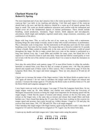
To prevent the risk of personal injury and/or death, make sure power is notapplied to the product until it is fully installed and ready for final testing. Allwork must be done with power turned off to the circuit being worked on.STEP 1.1Remove the WarmWire, SunStat thermostat, and SunStat sensor from their packages. Inspectthem for any visible damage. Verify everything is the correct size and type according to theplan and the order. Do not attempt to install a damaged product.STEP 1.2Record the product information. There is a factory-applied nameplate label on the powerleads. Do not remove this label. Record the cable serial number, model number, voltage,and cable resistance range in the Cable and Sensor Resistance Log (Table 4). If installingmore than one cable, do this for each of them.STEP 1.3Use a digital multi-meter set to the 200Ω or 2000Ω(2kΩ) range to measure the resistance betweenthe conductors of the cable power leads. Recordthese resistances in Table 4 under “Out of thebox before installation”. The resistance shouldmeasure within the resistance range on thenameplate label. If it is a little high or low, it maybe due to air temperatures or meter calibration.Consult the factory if in doubt.GroundLeadBlackLeadMeasure the resistance between either of thewhite or black leads and ground lead. Thismeasurement should be “open”, usually indicatedby an “OL” or a “I”. This is the same as displayedwhen the test leads are not touching anything.If there is any change in the reading, recordthis information and contact the factory beforecontinuing. This could indicate damage, testlead problems, or a number of other issues.Try “pinning” the test leads to the cable leadwires against a hard non-metal surface if thereadings continue to fluctuate.Change the meter to the 20,000 ohms (20 kΩ)range. Measure between the lead wires of theSunStat sensor. This resistance varies accordingto the temperature sensed. Table 3 providesapproximate resistance-to-temperature valuesfor reference.Whiteor BlueLead200 ohmsettingGroundLeadWhite orBlue LeadBlackLeadWhite orBlue LeadGroundLeadTable 3 - Floor Sensor Resistance ValuesTemperature55 F (13 C)65 F (18 C)75 F (24 C)85 F (29 C)Typical Values17,000 ohms13,000 ohms10,000 ohms8,000 ohmsBlackLead7 of 36 2016 Watts Water Technologies
Table 4 - Cable and Sensor Resistance LogCable 1Cable 2Cable serial numberCable modelCable voltageFactory cable resistance rangeOUT OF THE BOX BEFORE INSTALLATION (OHMS)Cable black to white (black to blue for 240VAC)Cable black to groundCable white to ground (blue to ground for 240VAC)Sensor wireAFTER CABLE AND SENSOR ARE FASTENED TO FLOOR (OHMS)Cable black to white (black to blue for 240VAC)Cable black to groundCable white to ground (blue to ground for 240VAC)Sensor wireAFTER FLOOR COVERINGS ARE INSTALLED (OHMS)Cable black to white (black to blue for 240VAC)Cable black to groundCable white to ground (blue to ground for 240VAC)Sensor wireRetain this log to retain the warranty! Do not discard!INSTALLATION NOTESIOM-WYF-WW 16168 of 36Cable 3
Phase 2 - Electrical Rough-inTo prevent the risk of personal injury and/or death, make sure power is notapplied to the product until it is fully installed and ready for final testing. Allwork must be done with power turned off to the circuit being worked on.STEP 2.1:Circuit Breaker (Overcurrent Protection)WarmWire must be protected against overload by a circuit breaker. GFCI type (ground faultcircuit interrupter) or AFCI type (arc-fault circuit interrupter) breakers may be used if desired,but are not necessary when using SunStat controls with integral GFCI.The rating of the breaker (see Table 5) is determined by the amp draw of the heating cables.Add the amp ratings of all cables to be connected to the SunStat control (see Table 2 or theNameplate Label on the cable). If the total is less than 12 amps, use a 15 or 20 Amp breaker(preference is 15 A). If the total is between 12 and 15 amps, use a 20 Amp breaker. If the totalis over 15 A, another circuit will be required with its own breaker and SunStat control.It may be possible to tap into anexisting circuit as long as thereis adequate capacity for thecables(s) and any additional appliance, such as a hair dryer orvacuum cleaner. Avoid circuitswhich have lighting, motors,exhaust fans, or hot tub pumpsdue to possible interference.STEP 2.2:Install Electrical BoxesTable 5Circuit Breakers and Supply WireCable(s)Supply WireBreakerVACtotal amps(AWG)*qty type**rating120 up to 12 amps141SP 15 or 20 A120 up to 15 amps121SP20 A240 up to 12 amps141DP 15 or 20 A240 up to 15 amps121DP20 A* Recommended only. Follow local codes for wire gauge size.** SP single-pole, DP double-poleSunStat Thermostat:Install an extra-deep electrical box for the SunStat Thermostat. Follow the instructionsincluded with the thermostat for complete information on location and wiring.SunStat Relay:Install an extra-deep electrical box for any SunStat Relay(s). The SunStat Relay is used whenmore than 15 amps must be controlled by one SunStat Thermostat. Follow the instructionsincluded with the SunStat Relay for complete information on location and wiring.Junction Boxes:I f a cable is to be located so its power lead is not long enough to reach the SunStat thermostator SunStat Relay directly, a junction box must be installed. Do not attempt to make a connectionto other wiring without a junction box. Use a standard junction box with a cover, mountingit below the subfloor, in the attic, in the wall, or in another location easily accessible after allcoverings are complete. If the SunStat sensor wire is not long enough to reach the SunStatthermostat directly, it may be extended. A junction box may be required by local code tomake this connection. Follow the installation instructions included with the SunStat for details.For construction with an existing wall or where the wall is covered, cut the necessary openingsto mount the electrical boxes listed above. Wait to install the boxes until all wiring is fed intothese locations to make it easier to pull the wire.9 of 36 2016 Watts Water Technologies
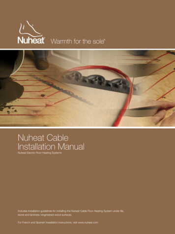
STEP 2.3:Bottom Plate WorkDrill or chisel holes at the bottom plate as indicated. One hole is for routing the power leadconduit and the other is for the thermostat sensor. These holes should be directly belowthe electrical box(es).Power leadconduitWireClipSensor wireIf going in to an existing wall, cut outdry wall and chisel out bottom plateto route wires to control.PowerleadSensor wireSTEP 2.4:Install Power Lead Conduit and Thermostat SensorPower Lead Conduit:The shielded power lead can be installed with or without electrical conduit (recommendedfor added protection against nails or screws) depending on code requirements. Removeone of the knock-outs in the electrical box to route the power lead. If electrical conduit is notrequired by code, install a wire collar to secure the power leads where they enter the box. Ifconduit is required by code, install 1/2" (minimum) conduit from the bottom plate up to theelectrical box. For multiple power leads (multiple cables) install 3/4" conduit.SunStat Thermostat Sensor:The SunStat sensor can be installed with or without electrical conduit depending on coderequirements. Conduit is recommended for added protection against nails or screws. Do notplace the sensor in the same conduit as the power leads to avoid possible interference. Opena separate knock-out in the bottom of the thermostat box. Feed the sensor (and conduit,if used) through the knock-out, down through the cut-out in the bottom plate, and out intothe floor where the heating cable will be installed. If the sensor wire needs to be securedto the wall stud, wait until after the cable and sensor are completely installed on the floor.STEP 2.5:Rough-in Wiring:Install appropriate 12 or 14 AWG electrical wire from the circuit breaker or branch circuitsource to the SunStat Thermostat electrical box (and SunStat Relay box(es) if needed)following all codes, see Table 5.If SunStat Relay(s) are used, feed appropriate wire (see SunStat Relay installation manualfor size and type) between the SunStat Relay(s) and the SunStat thermostat.See SunStat Relay instructions for details of wire size and type.IOM-WYF-WW 161610 of 36
There are 2 installation methods for securing WarmWire: HeatMatrix offers an easy way to install WarmWire while providing crack-isolation, vapormanagement and waterproofing for installations with tile or stone. To install, WarmWireis simply pressed into the HeatMatrix channels at a selected spacing. With HeatMatrix,the space between rows can be easily adjusted to accommodate additional wire orprovide more or less heat in defined areas. CableStrap is used for installations where crack-isolation and waterproofing are notrequired, or in areas that need a lower profile. CableStrap be covered with a smoothmortar finish for use under hardwood, laminate or resilient flooring. For CableStrapinstallation instructions, refer to Phase 4.Phase 3 - Cable Installation with HeatMatrixSTEP 3.1:Determine the area for HeatMatrixHeatMatrix is installed in both unheated and heated areas to provide crack-isolation andwaterproofing. Order a quantity that will cover the full square footage of the area to be tiled.STEP 3.2:Substrate preparationThe substrate must be flat, clean, dry, structurally sound, adequately load bearing and freefrom material which may prevent bonding with the cement mortar.STEP 3.3:Cut lengths of HeatMatrix to fit the installation areaMeasure and cut HeatMatrix to the required length for each row. Mark the boundary edgeon the subfloor to use as a guide for mortar application.STEP 3.4:Secure HeatMatrix to the substrate with mortarThe type of mortar used to secure the membrane to the subfloor depends on the typeof substrate. For most substrates, a premium modified thinset mortar is recommended.Apply the mortar for the first row using a 1/4" x 1/4" notched trowel. Place the cut lengthof HeatMatrix over the mortar. Position membrane, then readjust alignment if necessaryby lifting one end, and pulling lightly. Do not leave gaps between sections of HeatMatrixand ensure the pattern is aligned. Work HeatMatrix in using a float or flat trowel. The entiresurface of the fleece on the underside of the membrane should be securely bonded to themortar. Observe the mortar open time while working. Trim out any rough drain openings orother obstructions if necessary. Repeat the application process for each row until the spaceto be tiled is completely covered.STEP 3.5:Outline the heated areaMark the areas where the WarmWire cable will be installed. WarmWire should not be installed: Within 3" of the wall perimeter, door jamb, tub or shower base Within 6" of toilet flanges Under cabinets or fixtures that have no clearance under them Within confined spaces like closets or pantries where the heat cannot disperse, particularlywhen objects are left on the floor.Wire may be omitted from areas with no foot traffic. Refer to Appendix 1 for a table ofrecommended clearances.11 of 36 2016 Watts Water Technologies
STEP 3.6:Make sure the cable fitsCheck the cable size to ensure it will fit inside the Heated Area at the selected wire spacing(see Table 2)The heating cable CANNOT be cut to fit. It must be kept its original length and fullyembedded in the mortar in the floor. Any modification or mis‐use of the heating cable willvoid the warranty and cause potential shock or fire hazard.STEP 3.7:Decide the cable layoutDecide which direction the cables will run on the floor for the easiest coverage. Refer to thesample layouts in this manual for assistance. Depending on the shape of the area, it mayhelp to think of it in terms of several smaller areas.If more than one heating cable is to be installed in the area, all Power Leads must come backto the control or to a junction box and then to the control. Ensure there is sufficient spaceto allow this when planning the wire layout.NEVER run Power Leads across heating cables, under baseboard areas, or other potentiallydamaging areas.NEVER place heating cables closer than 2" from other heating cables.NEVER place heating cables closer than 1" from Power Leads.STEP 3.8:Position the Power Leads & Factory SpliceCarefully cut the tie binding the power lead coil. Do not nick the braid covering the powerlead. Locate the Factory Splice to ensure the power lead will reach the SunStat electricalbox or junction box location. It is acceptable to run the power leads several feet in the floorarea embedded in mortar if needed.Draw an outline around the Factory Splice and move it aside. Cut a shallow channel in theHeatMatrix to allow the Factory Splice to lay flat with the rest of the heating cable in the channel.Pull the Power Leads up into the wall or conduit.Add hot glue in the channel and set the Factory Splice and Power Lead in place.Completely embed the Factory Splice and heating cable in the floor mortar. Never bendthe factory splice. Never allow any part of the Factory Splice or heating cable to enter awall or cabinet or drop through the subfloor. Damage to the product will result.STEP 3.9:Install CablePress the heating cable into the HeatMatrix channels at the determined spacing. A handroller or grout float may be used to aid in installation.IOM-WYF-WW 161612 of 36
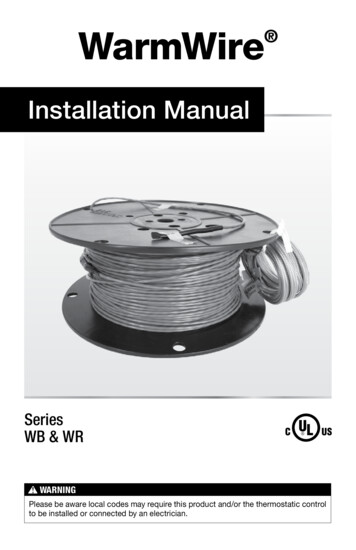
WarmWire spacing in HeatMatrix: Install WarmWire with 3-shapes in-between each row for approx. 12.3 W/ft2 heat output(standard spacing) Alternate between 3-shapes and 2 for a higher heat output of 14.8 W/ft2 Alternate between 3-shapes and 4 for a lower heat output of 10.6 W/ft23332 12.3 W/ft23 14.8 W/ft23 10.6 W/ft2343STEP 3.10Bench seatIf covering a bench seat or step area (not in a shower area), place a single run of cable upthe riser. Use a section of HeatMatrix to secure the cable to the seat at the desired spacing,then install a single run down the riser. Use an "s-shaped" curve to avoid sharp bends inthe cable at corners and help the cable to lay flat. The cable MUST be fully embedded inmortar and have approved floor coverings. Use hot glue where necessary to secure thecable flat against the riser.NEVER space the cables less than 2" apart at any point, and never less than 2.5" average.Never space more than 3.5" average.13 of 36 2016 Watts Water Technologies
Phase 4 - Cable Installation with CableStrap STEP 4.1:Floor CleaningThe floor must be completely swept of all debris including all nails, dirt, wood, and otherconstruction debris. Make absolutely sure there are no objects on the floor which mightdamage the wire.Wet mop the floor at least twice to ensure there is no dirt or dust. This will allow properbonding of the mortar and proper stick of any adhesives or double-sided tape used later.STEP 4.2:Outline the Heated AreaUse a marker to outline the area where the heating cable will be installed. Refer to theAppendix for a table of recommended clearances.Cabinet vanities: Draw the border right up to the toe-kick. The wire can be installed up to1" away from the vanity toe-kick.Tubs and shower entries: Draw the border about 3" from the edge of the tub or shower.Walls: Draw the border about 3" from the wall. If required to help the cable fit better, it maybe drawn 4" to 6" from the wall since people do not generally stand this close to a wallanyway. It may also be drawn closer, but be careful that the cable will not be placed underany trimwork. Keep the cable at least 6" from toilet flanges Do not run the cable under cabinets or fixtures that have no clearance under them. Avoid running the cable into a small closet or pantry. The heat cannot escape and thingscan be laid on the floor, blocking the heat and potentially overheating and causing afire hazard.STEP 4.3Make Sure the Cable FitsCheck the cable size to ensure it will fit inside the Heated Area at the selected wire spacing.See Table 2.Remember the heating cable length CANNOT be cut to fit. It must be kept its originallength and fully embedded in the mortar in the floor. Any modification or mis-use of theheating cable will void the warranty and cause potential shock or fire hazard.STEP 4.4Decide the LayoutDecide which direction the cables will run on the floor for the easiest coverage. Refer to thesample layouts in this manual for assistance. Depending on the shape of the area, it mayhelp to think of it in terms of several smaller areas.IOM-WYF-WW 161614 of 36
Install CableStrapSTEP 4.5Measure the edge of the Heated Area whereCableStrap will be installed.STEP 4.6Cut the CableStrap to length using metalshears.Concrete, self-level, or similar: Double-sidedtape (if included with your cable), hot glue, orstrong spray adhesive may be used if the flooris well cleaned and the strap is wiped free ofany oils. However, it is highly recommendedto also place screws at each end of the strap,and every 4 to 5 feet, to ensure it does notcome loose. If using a strong spray adhesive,apply to both the back of the strap and thefloor where it will be placed, and carefullyfollow all spray manufacturer’s instructionsand cautions.STEP 4.7Double-sided tapeSecure the strap to the floor. Depending onthe floor type, different methods may be used.ORHot gluePlywood, cement board, or similar: Galvanizednails or screws may be used to secure thestrap every 6" to 10".ORGalvanized nailsORSpray adhesiveScrewsCut another piece of strap for the other endof the area and secure to the floor.15 of 36 2016 Watts Water Technologies
Completely embed the
Keep this Manual for future reference. WarmWire is a simple, economical way to warm any floor, and provide years of lasting comfort. This instruction manual provides complete details, suggestions, and safety precautions for installing this floor-warming system. Fasten the cables to the floor. Then, depending on the floor coverings to be