Transcription
Product Data SheetPS-001885, Rev GNovember 2017Micro Motion Model 5700 Transmitters with MVD TechnologyRepeatable, reliable, accurate measurements Faster processing speed delivers the best response even in the most challenging applications such asmeter proving, filling & dosing, and batching Smart Meter Verification provides you with the confidence you need in your meter performance Zero verification confirms the calibration and indicates when it’s time to re-zero the meter Approved for custody transfer and certified for SIL2 and SIL3, which provides measurement confidenceand reliabilityA window into your process Easy access to detailed measurement history gives you valuable insight into your process for bettertroubleshooting and optimization Real-time indication of multi-phase flow events allow for greater process control High-accuracy density measurement reduces or eliminates waste in your process while the embeddedhistorian records upsets and process deviationsProductivity through simplified solutions Designed to minimize the time and expertise needed to install and operate the flowmeterUp to five fully configurable input/output channels that can be easily upgraded with changing needsEthernet version includes multiple protocols on dual channels, plus a configurable I/O channelFOUNDATION Fieldbus version includes IEC-61158-2 FOUNDATION Fieldbus output, a fixed mA outputchannel, and a configurable frequency / discrete output channel. Offline configuration and auditing through new file shuttling capability
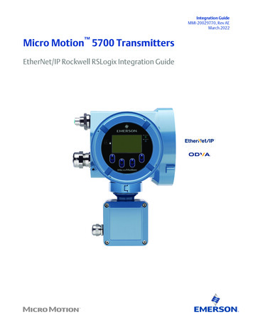
Model 5700 TransmittersNovember 2017Micro Motion Model 5700 transmittersModel 5700 transmitters deliver the best measurement technology and offer unparalleled support – ensuring total measurementconfidence, valuable process insight and greater operational efficiency. These transmitters provide the scalability, compatibility andperformance that your application demands.Simplified installation and commissioningAn intuitive interface, spacious side-access wiring compartment and convenient mounting brackets.Smart Meter Verification: advanced diagnostics for your entire systemOur online tool verifies that your meter performs as well as the day it was installed, giving you assurance in less than 90 seconds.Measurement history for easier troubleshooting and optimizationDetailed history files deliver key time-stamped information about your process from configuration changes and alerts to processevents and statistics.2www.micromotion.com
Model 5700 TransmittersNovember 2017Unmatched system connectivity and services interfacesConfigurable I/O versionUp to five fully configurable I/O channels with multiple mA, discrete and frequencyoutputs, and several powerful service interfaces.Ethernet versionTwo Ethernet outputs with EtherNet/IP, Modbus TCP, or PROFINET — plus one configurable output.Discrete input2 Ethernet ports1 configurableI/O channel formA, frequency,or discrete outputFieldbus versionFieldbus output, mA output, and a configurable channel for frequency or discreteoutput.Fieldbus outputmA outputConfigurable channelfor frequency ordiscrete outputwww.micromotion.com3
Model 5700 TransmittersNovember 2017Model 5700 enhancementsInternal memoryThe Model 5700 transmitter provides a backup of: Transmitter configurations Meter verification baseline and history Data log Licensing keyIf you need to replace your transmitter, move your old memory to the new transmitter without losing any data or licensinginformation.Software licensingSoftware licensing makes it possible to: Purchase permanent features and add them later Trial features, such as concentration measurement, for 60 days before buying Order up to five input/output channels through the licenseLarge graphical display Supports multiple languages Supports full configuration capabilities directly from the display Provides understandable alert codesTwo-phase flow detectionTwo-phase flow detection provides clear, concise information about fluid conditions, including notification about the followingthree fluid regimes: Single phase Moderate two-phase flow Severe two-phase flowPhysical design Conduit and terminal compartments are accessible from the sidesModular board stack designSpacious wiring compartmentsRemote mounting bracketA Universal Service Port (USP) connects and transfers data using standard, easily available equipmentTroubleshooting toolsThe Model 5700 transmitter stores data in non volatile memory with Real Time Clock, including: Meter fingerprint Audit trail Alert log Long term data historian: 5-minute Min, Max, Avg, Std Dev (10 years) Short term data historian: 1-second data (30 days)The Model 5700 transmitter contains descriptive alerts describing the issue and recommended steps for resolution. Follows NE 107 Standard4www.micromotion.com
November 2017Model 5700 TransmittersApplicationsApplications are custom designed programs and software that offer additional functionality andperformance to transmitters. These applications are available through options in the transmitter modelcode, see the ordering information section for details.Smart Meter VerificationProvides a quick, complete assessment of a Micro Motion Coriolis meter, determining whether the meterhas been affected by erosion, corrosion, or other influences affecting meter calibration. No secondaryreferences are required to perform this operation, and the meter can continue normal processmeasurement while the test is in progress.Smart Meter Verification Professional on the Model 5700 transmitter also offers coating detection,installation verification, detection of optimal flow range, and two-phase flow detection. A 90-day trialversion is included with all Model 5700 transmitters with enhanced core processors. After the 90-day trial, abasic version of Smart Meter Verification will provide simple pass/fail results, and simple diagnostics thatrun without interrupting your processes.Discrete batch control Simple batch control based on totalizer valuesFrequency output configured as discrete output for transmitters with analog or intrinsically safe outputsAutomatic overshoot compensationSingle and dual stage batching available on the configurable I/O version when ordered with the BatchingSoftware (BS) package option Batch ticket printing available if Channel E is enabled (supports Terminal Window, Generic, Epson TM88v,Epson TMU-295 and Digitec 6610A printers)NoteDiscrete batch control is not available with Model 5700 FOUNDATION Fieldbus models.Petroleum measurement and API correction option Accepts inputs from temperature and pressure devices Calculates values as per May, 2004 API Chapter 11.1- Relative density (specific gravity and API gravity) at reference temperature from observed density andtemperature- Volume corrected to reference temperature and pressure Calculates flow-weighted average temperature and flow-weighted average observed density (specificgravity and API gravity)www.micromotion.com5
Model 5700 TransmittersNovember 2017Concentration measurementProvides concentration measurement based on either industry-specific or liquid-specific units andrelationships. Standard measurement options include: Industry-specific:- Brix- Plato- Balling- Baumé at SG60/60- Specific gravity Liquid-specific:- %HFCS- Concentration derived from reference density- Concentration derived from specific gravityAdditionally, the application can be customized for site-specific concentration measurement (such as%HNO3, %NaOH).Advanced Phase Measurement Accurately measures liquid or gas flow in limited multiple-phase conditions- Immediate and continuous access to production or process data- Real time reporting of Gas Void Fraction (GVF) Facilitates reliable measurement at a fraction of the cost of true multi-phase meters- Historian automatically captures all production data- Little to no maintenance or calibration Combines with Net Oil Computer (NOC) or Concentration Measurement to measure two liquids in thepresence of gas- Provides single well real-time Net Oil and Net Water measurements- Improves Concentration Measurement in processes with intermittent entrained gasElectrical connectionsConfigurable I/O versionConnectionDescriptionInput/OutputUp to five pairs of wiring terminals for transmitter I/O and communicationsPower One pair of wiring terminals accepts AC or DC power One internal ground lug for power-supply ground wiringSensor 4-wire remote mount – 4 terminals for connection to 4-wire sensor 9-wire remote mount – 9 terminals for connection to 9-wire sensorService port (HART)Two clips for temporary connection to the service portUniversal Service Port (USP)A USP connected to commercially-available USB equipment and cables6www.micromotion.com
Model 5700 TransmittersNovember 2017Ethernet versionConnectionDescriptionEthernet portsTwo Ethernet ports for EtherNet/IP, Modbus TCP, PROFINET, and web server connectionsInput/OutputOne configurable channel for mA output, frequency output, discrete output, or discrete inputPower One pair of wiring terminals accepts AC or DC power One internal ground lug for power-supply ground wiringSensor 4-wire remote mount – 4 terminals for connection to 4-wire sensor 9-wire remote mount – 9 terminals for connection to 9-wire sensorUniversal Service Port (USP)A USP connected to commercially-available USB equipment and cablesEmbedded web serverConnect to embedded web server via Ethernet connection for on-board configurationor data transferFOUNDATION Fieldbus versionConnectionDescriptionInput/Output One fixed channel for mA output One configurable channel for frequency output or discrete outputThese outputs are available as intrinsically safe, or non-intrinsically safe, based onthe output option selected.Power One pair of wiring terminals accepts AC or DC power One internal ground lug for power-supply ground wiringSensor 4-wire remote mount – 4 terminals for connection to 4-wire sensor 9-wire remote mount – 9 terminals for connection to 9-wire sensorUniversal Service Port (USP)A USP connected to commercially-available USB equipment and cablesNote Each screw terminal connection accepts one or two solid conductors, 24 to 12 AWG (0.20 to 3.3 mm2) or one or two strandedconductors, 22 to 14 AWG (0.38 to 2.3 mm2). Each plug type connector accepts one stranded or solid conductor, 24 to 12 AWG(0.20 to 3.3 mm2). For integral mount transmitters (mounting code I), the connection between the transmitter and the sensor is not normallyaccessed.www.micromotion.com7
Model 5700 TransmittersNovember 2017Input/output signal detailConfigurable I/O channels (output board code A)SignalChannel AChannel BWiring terminals1mA inputsand outputsmA Output 1 (HART)23Channel C45Channel D67Channel E89mA Output 2mA Output 3mA InputFrequencyoutputsFrequency Output2(1)Frequency Output 1Frequency Output 2DiscreteoutputsDiscrete Output 1Discrete Output 2Discrete Output 3Discrete Input 1Discrete Input 2DiscreteinputsFrequencyinputs10RS-485Frequency Input(1) Frequency Output 2 can be mapped to Channel B or D. For multiple frequency outputs, use Frequency 1 on Channel C and Frequency 2 on eitherChannel B or D.Ethernet channels (output board code C)SignalChannel AChannel BChannel CChannel optionsEtherNet/IP(1)EtherNet/IPmA OutputModbus TCPModbus TCPFrequency OutputPROFINETPROFINETDiscrete OutputDiscrete Input(1) The same protocol must be ordered on both Channel A and B. ProLink III and the Integrated Webserver can always be connected to either ChannelA or B.FOUNDATION Fieldbus channels (output board code E with intrinsically safe H1 outputs)SignalChannel AChannel CChannel DChannel optionsFOUNDATION Fieldbus (FISCO “ia”or FISCO “ic”)IS mA OutputIS Frequency OutputIS Discrete OutputFOUNDATION Fieldbus channels (output board code N with H1 outputs)SignalChannel AChannel CChannel DChannel optionsFOUNDATION FieldbusmA OutputFrequency OutputDiscrete Output8www.micromotion.com
Model 5700 TransmittersNovember 2017Channel A specificationsConfigurable I/O (output board code A)SpecificationmA outputmA output max loop resistanceInternal voltage (active power)24VDC (nom)820 ohmExternal voltage (passive power)30VDC (max)1080 ohm @ 30VDCScalable range4-20mADownscale faultConfigurable from 1.0 – 3.6 mA, defaultvalue 2.0 mAUpscale faultConfigurable from 21.0 – 23.0 mA, default value 22.0 mALinearity0.015 % Span, Span 16mANotemA output is linear with process from 3.8 to 20.5 mA, per NAMUR NE-43 (February 2003).Ethernet (output board code C)Specifications: 10BASE-T 100BASE-TXFOUNDATION Fieldbus (output board code E)Specifications: FOUNDATION Fieldbus H1 output Wiring is intrinsically safe with intrinsically safe power supply Transmitter fieldbus circuit is passive, and draws power from the fieldbus segment — current draw is 13 mA Manchester encoded digital signal conforms to IEC 61158-2FOUNDATION Fieldbus (output board code N)Specifications: FOUNDATION Fieldbus H1 output FOUNDATION Fieldbus wiring is non-incendive Transmitter fieldbus circuit is passive, and draws power from the fieldbus segment — current draw is 13 mA Manchester encoded digital signal conforms to IEC 61158-2Channel B specificationsConfigurable I/O (output board code A)SpecificationmA outputmA output max loopresistanceFrequency output (2)Discrete output (1)Internal voltage(active power)24VDC (nom)820 ohm24VDC (nom)24VDC (nom)22mA sourcing7mA sourcingwww.micromotion.com9
Model 5700 TransmittersNovember 2017SpecificationmA outputmA output max loopresistanceFrequency output (2)Discrete output (1)External voltage(passive power)30VDC (max)1080 ohm @ 30VDC30VDC (max)30VDC (max)500mA (max) sinking500mA (max) sinkingScalable range4-20mA0.01 Hz – 10 kHzDownscale faultConfigurable from 1.0 – 3.6mA, default value 2.0 mA0HzUpscale faultConfigurable from 21.0 – 23.0mA, default value 22.0 mAConfigurable from 10Hz to 14.5 kHz, defaultvalue 14.5 kHzLinearity0.015 % Span, Span 16mAOutput is linear withflow rate to 12.5 kHzResolution /- 1 pulseEthernet (output board code C)Specifications: 10BASE-T 100BASE-TXFOUNDATION FieldbusTable 1: Output board code ESpecificationmA OutputmA Output max loop resistanceExternal voltage (passive power)30VDC (max)869 ohms @ 30V10VDC (min)Scalable range4-20mADownscale faultConfigurable from 1.0 – 3.6 mA, defaultvalue 2.0 mAUpscale faultConfigurable from 21.0 – 23.0 mA, default value 22.0 mALinearity0.015 % Span, Span 16mAEntity parameters Ui 30VIi 484mAPi 2.05WCi 0.27nFLi 5uHTable 2: Output board code NSpecificationmA OutputmA Output max loop resistanceExternal voltage (passive power)30VDC (max)869 ohms @ 30V10VDC (min)Scalable range4-20mADownscale faultConfigurable from 1.0 – 3.6 mA, defaultvalue 2.0 mA10www.micromotion.com
Model 5700 TransmittersNovember 2017Table 2: Output board code N (continued)SpecificationmA OutputmA Output max loop resistanceUpscale faultConfigurable from 21.0 – 23.0 mA, default value 22.0 mALinearity0.015 % Span, Span 16mANote mA output is linear with process from 3.8 to 20.5 mA, per NAMUR NE-43 (February 2003). Fieldbus Channel B graph and equationsA.B.C.D.Loop resistor (ohms)Supply voltage VDC (volts)Rmax max value of loop resistor allowedRmin min value of loop resistance requiredLoop Resistance EquationRmax (Vsupply - 10V)/0.023Rmin 0 Ω , Vsupply 25VRmin 200 Ω, Vsupply 25VChannel C specificationsConfigurable I/O (output board code A) and Ethernet (output board code C)SpecificationmA outputmA output maxloop resistanceFrequency output(1)Discrete output(2)Discrete inputInternal voltage(active power)24VDC (nom)820 ohm24VDC (nom)24VDC (nom)24VDC (nom)22mA sourcing7mA sourcing7mA sourcingExternal voltage(passive power)30VDC (max)30VDC (max)30VDC (max)30VDC (max)500mA (max) sinking500mA (max) sinkingwww.micromotion.com1080 ohm @30VDC11
Model 5700 TransmittersNovember 2017mA output maxloop resistanceFrequency output(1)SpecificationmA outputScalable range4-20mA0.01 Hz – 10 kHzDownscale faultConfigurable from1.0 – 3.6 mA, default value 2.0mA0HzUpscale faultConfigurable from21.0 – 23.0 mA, default value 22.0mAConfigurable from10 Hz to 14.5 kHz,default value 14.5 kHzResolutionLinearityDiscrete output(2)Discrete input /- 1 pulse0.015 % Span, Span 16mAOutput is linearwith flow rate to12.5 kHzMaximum positivethreshold3VDCMinimum negativethreshold0.6VDC(1) Load resistor (500 Ω resistance recommended for 24V supply.) Use the following equations for other load resistance values: Rmax [(Vsupply 6V) / 0.003] - Rbarrier (maximum value of load resistor allowed) Rmin 0 ohms(2) Current (Vsupply - 0.8V) / (1690 ohms barrier internal resistance in ohms load resistor in ohms)NotemA output is linear with process from 3.8 to 20.5 mA, per NAMUR NE-43 (February 2003).FOUNDATION Fieldbus (output code E)SpecificationFrequency output(1)Discrete output(2)External voltage (passive power)30 VDC (max)30 VDC (max)8 VDC(min)8 VDC (min)Scalable range0.01 Hz - 10 kHzDownscale fault0HzUpscale faultConfigurable from 10 Hz to 14.5 kHz, default value 14.5 kHzResolution /- 1 pulseEntity parameters Ui 30VIi 484mAPi 2.05WCi 11.27nFLi 5uH(1) Load resistor (500 Ω resistance recommended for 24V supply.) Use the following equations for other load resistance values: Rmax [(Vsupply 6V) / 0.003] - Rbarrier (maximum value of load resistor allowed) Rmin 0 ohms(2) Current (Vsupply - 0.8V) / (1690 ohms barrier internal resistance in ohms load resistor in ohms)12www.micromotion.com
Model 5700 TransmittersNovember 2017FOUNDATION Fieldbus (output code N)SpecificationFrequency output(1)Discrete output(2)External voltage (passive power)30 VDC (max)30VDC (max)8 VDC(min)(3)8 VDC (min)(4)Scalable range0.01 Hz - 10 kHzDownscale fault0HzUpscale faultConfigurable from 10 Hz to 14.5 kHz, default value 14.5 kHzResolution /- 1 pulse(1) Load resistor (500 Ω resistance recommended for 24V supply.) Use the following equations for other load resistance values: Rmax [(Vsupply 6V) / 0.003] - Rbarrier (maximum value of load resistor allowed) Rmin 0 ohms(2) Current (Vsupply - 0.8V) / (1690 ohms barrier internal resistance in ohms load resistor in ohms)(3) Load resistor (500 Ω resistance recommended for 24V supply.) Use the following equations for other load resistance values: Rmax [(Vsupply 6V) / 0.003] (maximum value of load resistor allowed) Rmin 250 ohms (minimum value of load resistance required)(4) Current (Vsupply - 0.8V) / (1690 ohms load resistor in ohms)Channel D specificationsChannel D specifications do not apply to Ethernet or FOUNDATION Fieldbus implementations.Configurable I/O (output board code A)Frequency output(2)mA inputDiscrete output(3)Discrete input (2)Frequency inputInternal voltage(active power)24VDC (nom)24VDC (nom)24VDC (nom)24VDC (nom)24VDC (nom)2.21kilo ohm pullup resistor2.21 kilo ohm pullup resistor2.21 kilo ohm pullup resistorExternal voltage(passive power)30VDC (max)30VDC (max)30VDC (max)30VDC (max)Scalable range0.01 Hz – 10 kHzMax frequency100 Hz3500 HzMaximum positivethreshold3VDC3VDCSpecification2.21 kilo ohm pullup resistor30VDC (max)500mA (max) sinking500mA (max) sinking4 - 20 mAFault indication ifmA input drops below 3.8 mA or goesabove 20.5 mADownscale fault0HzUpscale faultConfigurable from10 Hz to 14.5 kHz,default value 14.5 kHzAccuracy /- 1 pulseInput resistancewww.micromotion.com100 ohm13
Model 5700 TransmittersSpecificationFrequency output(2)November 2017mA inputDiscrete output(3)Minimum negativethresholdDiscrete input (2)Frequency input0.6VDC0.6VDCChannel E specificationsChannel E is not available for Ethernet or FOUNDATION Fieldbus configurations.Output optionSpecificationConfigurable I/O (output board code A)RS-485 ModbusSensor input mounting codesMounting codesDescriptionI (integral mount)Integrally mounted to sensor, no external input connectionC (9-wire remote mount)One 9-wire sensor signal input connection, intrinsically safeR (4-wire remote mount)One 4-wire sensor signal input connection, intrinsically safeDigital communicationsProtocolsOutputs and descriptionsModbus/USP Modbus/RS-485,HART/RS-485 Available on Channel E, if purchased One RS-485 output can be used for direct connection to HART or Modbus host systems Accepts data rates between 1200 baud and 38.4 kilobaud 115.2 kilobaud is also available as a special order item Uses the latest HART 7 standardHART/Bell 202 Available on Channel A, if purchased HART Bell 202 signal is superimposed on the primary milliamp output, and is available for host system interface Requires 250 to 600 ohms load resistance Uses the latest HART 7 standard14One service port that can be used for a temporary connection onlyConnects to a PC via USB as if the transmitter had a built-in USB/RS-485 converterSupports all Modbus data ratesRequires a USB A/male-to-A/male cablewww.micromotion.com
Model 5700 TransmittersNovember 2017ProtocolsOutputs and descriptionsFOUNDATION Fieldbus Available on Channel A Models/output codes: - Model 5700 with output code E is FISCO “ia” certified in Zone 1 / Div 1and isFISCO “ic” certified in Zone 2 / Div 2 (formerly known as FNICO)- Model 5700 with output code N Transmitters are registered with the Fieldbus Foundation, and conform to theFOUNDATION Fieldbus H1 protocol specification. FISCO: - Field device in compliance with EN 60079-11:2012 and IEC 60076-11:2011- Ui 33 V, Ii 380 mA, Pi 5.32 W, Ci 0.27 nF, Li 5 µHEtherNet/IP/Ethernet Available on Channel A and Channel B Supports Auto Negotiate with date rates of 10 MB and 100 MB and half and fullduplex Supports Auto Detect of Ethernet Crossover cables Supports Dynamic Host Configuration Protocol (DHCP) Supports Device Level Ring (DLR) Supports Address Conflict Detection (ACD) Supports Quality of Service (QoS) Supports file object for EDS download Conforms to ODVA EtherNet/IP Specification CT 12 Conforms to the 10BASE-T and 100BASE-TX Ethernet standardsModbus TCP/Ethernet Available on Channel A and Channel B Supports Auto Negotiate with data rates of 10 MB and 100 MB and half and fullduplex Supports Auto Detect of Ethernet Crossover cables Supports Dynamic Host Configuration Protocol (DHCP) Uses v1.1b of the Modbus TCP standard Conforms to the 10BASE-T and 100BASE-TX Ethernet standardsPROFINET/Ethernet Available on Channel A and Channel B Supports Auto Negotiate with data rates of 10 MB and 100 MB and half and fullduplex Supports Auto Detect of Ethernet Crossover cables Conforms to Conformance Class A v2.31 standard Conforms to the 10BASE-T and 100BASE-TX Ethernet standardsModel 5700 with FOUNDATION Fieldbus supportFieldbus software functionalityModel 5700 FOUNDATION Fieldbus software is designed to permit remote testing and configuration of the transmitter using the DeltaV Fieldbus Configuration Tool, or other FOUNDATION Fieldbus compliant hosts. The Coriolis sensor signal is channelledthrough the flowmeter to the control room and the FOUNDATION Fieldbus configuration device.Transducer blocksTransducer blocks hold data from the Coriolis sensor, including process variables, configuration, calibration, and diagnostics.The Model 5700 transmitter with FOUNDATION Fieldbus provides up to seven transducer blocks: Measurement - For process and diagnostic variables and configuration of process parameters.www.micromotion.com15
Model 5700 TransmittersNovember 2017 Device - For device, display, channels configuration and device alert informationTotal inventory - For configuration of device totals and inventoriesMeter Verification - For Smart Meter VerificationAPI referral - For petroleum measurement calculations using API MPMS Chapter 11.1- For complex density and concentration calculations (e.g.,%HFCS, SG60/60) Concentration Measurement APM - For Advance Phase Measurement and NOC calculationsResource blockThe resource block contains physical device information, including available memory, manufacturer identification, type of device,and features.Analog input function blocksThe Analog Input (AI) function block processes the measurement from the Coriolis sensor and makes it available to other functionblocks. It also allows filtering, alarm handling, and engineering unit changes. Each of the four Model 5700 AI blocks can be assignedto one of 27 available variables. There are four permanent Analog Input function blocks.Analog output function blocksThe AO function block assigns an output value to a field device through a specified channel. The block supports mode control, signalstatus calculation, and simulation. The AO block can report pressure from an external pressure source, temperature from anexternal temperature source, or watercut from an external device. There are two permanent Analog Output function blocks.Discrete input function blockOne permanent Discrete Input (DI) function block can be assigned to any of the Discrete Input variable channels in the transducerblock. The DI block channels are: forward/reverse indication, zero in progress, fault condition indication, and meter verificationfailure.Discrete output function blockOne permanent Discrete Output (DO) function block can be assigned to any of the Discrete Output variable channels in thetransducer block. The DO block channels are: Start Sensor Zero, Increment CM Curve, Start Meter Verification in ContinuousMeasurement Mode, Reset All Process Totals, Start/Stop All Totals, Reset Config Totals 1-7.Proportional integral derivative function blockOne permanent Proportional Integral Derivative (PID) function block combines all the necessary logic to perform proportional/integral/derivative control. The block supports mode control, signal scaling and limiting, feed forward control, override tracking,alarm limit detection, and signal status propagation.Integrator function blockTwo permanent Integrator (INT) function blocks provides functionality for the transmitter totalizers. Any of seven internal totals orany of seven internal inventories can be selected and reset.Diagnostics and serviceModel 5700 transmitters automatically perform continuous self diagnostics. Using the Device transducer block, the user canperform on-line testing of the transmitter and sensor. Diagnostics are event driven and do not require polling for access. PlantWeb Field Diagnostic is supported. The diagnostic information is based on NAMUR NE 107 standard.16www.micromotion.com
Model 5700 TransmittersNovember 2017Power supply Self switching AC/DC input, automatically recognizes supply voltage Complies with Low Voltage Directive 2014/35/EU per IEC 61010-1 Ed. 3.0 2010-06; Over voltage Category II, Pollution Degree 2 For European installations, install a switch or circuit breaker that is suitably located and easily reached. Mark the switch or circuitbreaker as the disconnecting device for the transmitter, in compliance with the Low Voltage Directive 2014/35/EU.TypeValueAC power 85 to 265 VAC, 50/60 Hz 6 watts typical, 11 watts maximumDC power 18 to 100 VDC 6 watts typical, 11 watts maximum Size the length and diameter of power conductors to provide 18VDC minimum atthe power terminals at a load current of 0.7AFuse1.5A Slow Blow (UL 248-14)Environmental limitsAmbient temperature limitsTypeFahrenheitCelsiusOperating–40 to 149 F–40 to 65 CNoteThe display can lose visibility below –22 F (–30 C).Storage–40 to 185 F–40 to 85 CVibration limitsMount typeValueNon truck mountMeets IEC 60068-2-6, endurance sweep, 5 to 2000 Hz, 50sweep cycles at 1.0 gTruck mountMeets IEC 60068-2-6, endurance sweep, 5 to 2000 Hz, 50sweep cycles at 1.0 g (remote mount)Humidity limitsThe humidity limits are 5 to 95% relative humidity, non-condensing at 140 F (60 C).Environmental effectsEMI effectsComplies with: EMC directive 2014/30/EU NAMUR NE-21 (09.05.2012)www.micromotion.com17
Model 5700 TransmittersNovember 2017Ambient temperature effectAmbient temperature effect on mA outputs shall not exceed /-0.005% of span per degree C.Hazardous area classificationsCSA CSA-US Ambient temperature is limited to -40 F (-40 C) to 149 F (65 C) for CSA compliance. Class I, Div. 1, Groups C and D. Class II, Div. 1, Groups E, F, and G explosion proof (when installed with approved conduit seals).Otherwise, Class I, Div. 2, Groups A, B, C, and D. Provides nonincendive sensor outputs for use in Class I, Div. 2, Groups A, B, C, and D; or intrinsically safe sensor outputs for use inClass I, Div. 1, Groups C and D or Class II, Div. 1, Groups E, F, and G.CodeDescriptionAAClass I, Div. 1, Groups C and D. Class I, Div. 2, groups A,B,C,D Class II, Div. 1, Groups E, F, and G explosion proof(when installed with approved conduit seals).2AClass I, Div. 2, Groups A, B, C, and D.IECExAmbient temperature range is -40 F (-40 C) to 149 F (65 C) for IECEx compliance.Configurable I/O — ordering code ANoteFor EA and 3A approval codes, the marking will change when installed with Smart Wireless 775 THUM.ClassificationFlameproofIncreased safetyNon sparking with an integraltransmitter on the sensorNon sparking with a remotetransmitter on the sensor18Approval codeIAEA3A3AApprovalStandard displayEx db [ib] IIB H2 T6 GbNo display or IIC displayEx db [ib] IIC T6 GbDust markingEx tb [ib] IIIC T75 C Db IP66/IP67Standard displayEx db e [ib] IIB H2 T6 GbNo display or IIC displayEx db e [ib] IICT6 GbDust markingEx tb [ib] IIIC T75 C Db IP66/IP67Standard displayEx nA nC IIB H2 T5GcNo display or IIC displayEx nA nC IIC T5 GcDust markingEx tc IIIC T75 C Dc IP66/IP67Standard displayEx nA nC [ib Gb] IIB H2 T5 GcNo display or IIC displayEx nA nC [ib Gb] IIC T5 GcDust markingEx tc [ib Db] IIIC T75 C Dc IP66/IP67www.micromotion.com
Model 5700 TransmittersNovember 2017Ethernet — ordering code CClassificationFlameproofNon sparking with an integraltransmitter on the sensorNon sparking with a remotetransmitter on the sensorApproval codeIA3A3AApprovalStandard displayEx db [ib] IIB H2 T6 GbNo display or IIC display
Micro Motion Model 5700 transmitters Model 5700 transmitters deliver the best measurement technology and offer unparalleled support - ensuring total measurement confidence, valuable process insight and greater operational efficiency. These transmitters provide the scalability, compatibility and performance that your application demands.