Transcription
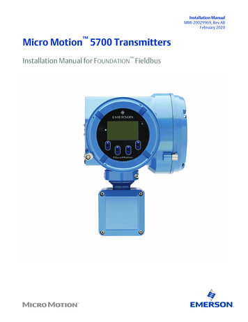
Installation ManualMMI-20029969, Rev ABFebruary 2020Micro Motion 5700 TransmittersInstallation Manual for FOUNDATION Fieldbus
Safety messagesSafety messages are provided throughout this manual to protect personnel and equipment. Read each safety message carefullybefore proceeding to the next step.Safety and approval informationThis Micro Motion product complies with all applicable European directives when properly installed in accordance with theinstructions in this manual. Refer to the EU declaration of conformity for directives that apply to this product. The EU declarationof conformity, with all applicable European directives, and the complete ATEX Installation Drawings and Instructions are availableon the internet at www.emerson.com or through your local Micro Motion support center.Information affixed to equipment that complies with the Pressure Equipment Directive, can be found on the internet atwww.emerson.com.For hazardous installations in Europe, refer to standard EN 60079-14 if national standards do not apply.Other informationFull product specifications can be found in the product data sheet. Troubleshooting information can be found in the configurationmanual. Product data sheets and manuals are available from the Micro Motion web site at www.emerson.com.Return policyFollow Micro Motion procedures when returning equipment. These procedures ensure legal compliance with governmenttransportation agencies and help provide a safe working environment for Micro Motion employees. Micro Motion will not acceptyour returned equipment if you fail to follow Micro Motion procedures.Return procedures and forms are available on our web support site at www.emerson.com, or by phoning the Micro MotionCustomer Service department.Emerson Flow customer serviceEmail: Worldwide: flow.support@emerson.com Asia-Pacific: APflow.support@emerson.comTelephone:2North and South AmericaEurope and Middle EastAsia PacificUnited States800-522-6277U.K. and Ireland0870 240 1978Australia800 158 727Canada 1 303-527-5200The Netherlands 31 (0) 704 136666New Zealand099 128 804Mexico 52 55 5809 5300France 33 (0) 800 917901India800 440 1468Argentina 54 11 4837 7000Germany0800 182 5347Pakistan888 550 2682Brazil 55 15 3413 8000Italy 39 8008 77334China 86 21 2892 9000Chile 56 2 2928 4800Central & Eastern 41 (0) 41 7686111Japan 81 3 5769 6803Peru 51 15190130Russia/CIS 7 495 995 9559South Korea 82 2 3438 4600Egypt0800 000 0015Singapore 65 6 777 8211Oman800 70101Thailand001 800 441 6426Qatar431 0044Malaysia800 814 008Kuwait663 299 01South Africa800 991 390Saudi Arabia800 844 9564UAE800 0444 0684
Installation ManualMMI-20029969ContentsFebruary 2020ContentsChapter 1Before you begin. 51.1 About this document.51.2 Hazard messages.51.3 Related documentation.5Chapter 2Planning. 72.1 Installation checklist. 72.2 Additional considerations for retrofitting existing installations. 82.3 Power requirements. 8Chapter 3Mounting and sensor wiring. 113.1 Mounting and sensor wiring for integral-mount transmitters. 113.2 Mounting transmitters. 113.3 Wire a remote-mount transmitter to the sensor. 153.4 Ground the meter components. 183.5 Rotate the transmitter on the sensor (optional).193.6 Rotate the user interface on the transmitter (optional).203.7 Rotate the sensor wiring junction box on a remote-mount transmitter (optional). 21Chapter 4Wiring the channels. 234.1 Available channels. 234.2 Access the wiring channels. 234.3 I/O wiring. 244.4 FISCO-input entity parameters. 254.5 Wiring for nonhazardous installations. 264.6 Wiring for hazardous installations.29Chapter 5Wiring the power supply.35Chapter 6Power up the transmitter. 37Chapter 7Guided setup.39Chapter 8Using the display controls. 41Chapter 9Available service port connection.43Installation Manualiii
ContentsFebruary 2020ivInstallation ManualMMI-20029969Micro Motion 5700 transmitters for FOUNDATION Fieldbus
Installation ManualMMI-200299691Before you begin1.1About this documentBefore you beginFebruary 2020This manual provides information on planning, mounting, wiring, and initial setup of the5700 transmitter. For information on full configuration, maintenance, troubleshooting, orservice of the transmitter, see the configuration and use manual.The information in this document assumes that users understand basic transmitter andsensor installation, configuration, and maintenance concepts and procedures.1.2Hazard messagesThis document uses the following criteria for hazard messages based on ANSI standardsZ535.6-2011 (R2017).DANGERSerious injury or death will occur if a hazardous situation is not avoided.WARNINGSerious injury or death could occur if a hazardous situation is not avoided.CAUTIONMinor or moderate injury will or could occur if a hazardous situation is not avoided.NOTICEData loss, property damage, hardware damage, or software damage can occur if asituation is not avoided. There is no credible risk of physical injury.Physical accessNOTICEUnauthorized personnel can potentially cause significant damage and/or misconfigurationof end users' equipment. Protect against all intentional or unintentional unauthorized use.Physical security is an important part of any security program and fundamental toprotecting your system. Restrict physical access to protect users' assets. This is true for allsystems used within the facility.1.3Related documentationYou can find all product documentation on the product documentation DVD shipped withthe product or at www.emerson.com.See any of the following documents for more information: Micro Motion 5700 Product Data Sheet Micro Motion 5700 Transmitters for FOUNDATION Fieldbus: Configuration and Use ManualInstallation Manual5
Before you beginFebruary 2020Installation ManualMMI-20029969 Modbus Interface Tool Sensor installation manual6Micro Motion 5700 transmitters for FOUNDATION Fieldbus
Installation ManualMMI-20029969PlanningFebruary 20202Planning2.1Installation checklist If possible, install the transmitter in a location that will prevent direct exposure tosunlight. The environmental limits for the transmitter may be further restricted byhazardous area approvals. If you plan to mount the transmitter in a hazardous area:WARNING— Verify that the transmitter has the appropriate hazardous area approval. Eachtransmitter has a hazardous area approval tag attached to the transmitterhousing.— Ensure that any cable used between the transmitter and the sensor meets thehazardous area requirements.— For ATEX/IECEx installations, strictly adhere to the safety instructionsdocumented in the ATEX/IECEx approvals documentation available on theproduct documentation DVD shipped with the product or at www.emerson.com. Verify that you have the appropriate cable and required cable installation parts for yourinstallation. For wiring between the transmitter and sensor, verify the maximum cablelength does not exceed 1,000 ft (305 m). Ensure that you use the following cables for the different connections:— A certified FOUNDATION fieldbus cable for FOUNDATION fieldbus terminals— A shielded, twisted-pair instrument cable with drain for all output connections You can mount the transmitter in any orientation as long as the conduit openings ortransmitter display do not point upward.Installing the transmitter with the conduit openings or transmitter display facingupward risks condensation moisture entering the transmitter housing, which coulddamage the transmitter.Following are examples of possible orientations for the transmitter.Preferred orientation Installation ManualAlternate orientationsMount the meter in a location and orientation that satisfies the following conditions:— Allows sufficient clearance to open the transmitter housing cover. Install with 8 in(203 mm) to 10 in (254 mm) clearance at the wiring access points.7
PlanningFebruary 2020Installation ManualMMI-20029969— Provides clear access for installing cabling to the transmitter.— Provides clear access to all wiring terminals for troubleshooting.2.2Additional considerations for retrofittingexisting installations The transmitter installation may require 3 in (76 mm) to 6 in (152 mm) of additionalwiring for the input/output and power connections. This length would be in addition tothe currently installed wiring. Confirm you have the additional wiring necessary for thenew installation. Before removing the existing transmitter, be sure to record the configuration data forthe currently installed transmitter. At initial startup of the newly installed transmitter,you will be prompted to configure the meter via a guided setup.Record the following information (if applicable):VariableSettingTagMass flow unitsVolume flow unitsDensity unitsTemperature unitsCalibration parameters (for 9-wire installations only)Flow calibration factorFCF (Flow Cal or Flow Calibration Factor):Density calibration factors— D1:— D2:— K1:— K2:— TC:— FD:Function block settingsChannel assignmentL TypeXD scale (engineering unitsassignment)2.3Power requirementsSelf-switching AC/DC input, automatically recognizes supply voltage: 85 to 240 VAC, 50/60 Hz, 6 watts typical, 11 watts maximum8Micro Motion 5700 transmitters for FOUNDATION Fieldbus
Installation ManualMMI-20029969PlanningFebruary 2020 18 to 100 VDC, 6 watts typical, 11 watts maximumNoteFor DC power: Power requirements assume a single transmitter per cable. At startup, the power source must provide a minimum of 1.5 amps of short-termcurrent per transmitter and not pull voltage below 18 VDC. Length and conductor diameter of the power cable must be sized to provide 18 VDCminimum at the power terminals, at a load current of 0.7 amps.Cable sizing formulaM 18V (R x L x 0.5A) M: minimum supply voltage R: cable resistance (in Ω/ft) L: cable length (in ft)Typical power cable resistance at 68 F (20.0 C)2.3.1Wire gaugeResistance14 AWG0.0050 Ω/ft16 AWG0.0080 Ω/ft18 AWG0.0128 Ω/ft20 AWG0.0204 Ω/ft2.5 mm20.0136 Ω/m1.5 mm20.0228 Ω/m1.0 mm20.0340 Ω/m0.75 mm20.0460 Ω/m0.50 mm20.0680 Ω/mMaximum cable lengths between sensor and transmitterThe maximum cable length between the sensor and transmitter that are separatelyinstalled is determined by cable type.Cable typeWire gaugeMaximum lengthMicro Motion 4-wire remotemountNot applicable 1,000 ft (305 m) withoutEx-approval 500 ft (152 m) with IICrated sensors 1,000 ft (305 m) with IIBrated sensorsMicro Motion 9-wire remotemountInstallation ManualNot applicable60 ft (18 m)9
PlanningFebruary 202010Installation ManualMMI-20029969Cable typeWire gaugeMaximum lengthUser-supplied 4-wireVDC 22 AWG (0.326 mm²)300 ft (91 m)VDC 20 AWG (0.518 mm²)500 ft (152 m)VDC 18 AWG (0.823 mm²)1,000 ft (305 m)RS-485 22 AWG (0.326 mm²)or larger1,000 ft (305 m)Micro Motion 5700 transmitters for FOUNDATION Fieldbus
Installation ManualMMI-20029969Mounting and sensor wiringFebruary 20203Mounting and sensor wiring3.1Mounting and sensor wiring for integralmount transmittersThere are no separate mounting requirements for integral transmitters, and no need toconnect wiring between the transmitter and the sensor.3.2Mounting transmittersThere are two options available for mounting transmitters: Mount the transmitter to a wall or flat surface. Mount the transmitter to an instrument pole.3.2.1Mounting the transmitter to a wall or flat surfacePrerequisites Micro Motion recommends 5/16-18 (8 mm–1.25) fasteners that can withstand theprocess environment. Micro Motion does not supply bolts or nuts as part of thestandard offering (general purpose bolts and nuts are available as an option). Ensure that the surface is flat and rigid, does not vibrate, or move excessively. Confirm that you have the necessary tools, and the mounting kit shipped with thetransmitter.Procedure1. Attach the mounting bracket to the transmitter and tighten the screws to 80 in lbf(9.04 N m) to 90 in lbf (10.17 N m).Installation Manual11
Mounting and sensor wiringFebruary 2020Installation ManualMMI-20029969Figure 3-1: Mounting bracket to an aluminum transmitterFigure 3-2: Mounting bracket to a stainless steel transmitter2. For wall-mount installations, secure the mounting bracket to the prepared surface.12Micro Motion 5700 transmitters for FOUNDATION Fieldbus
Installation ManualMMI-20029969Mounting and sensor wiringFebruary 2020Figure 3-3: Wall-mounting bracket and dimensions for an aluminumtransmitterA. 2.8 in (71 mm)B. 2.8 in (71 mm)Figure 3-4: Wall-mounting bracket and dimensions for a stainless steeltransmitterA. 7.51 in (190.8 mm)B. 3.67 in (93.2 mm)Installation Manual13
Mounting and sensor wiringFebruary 2020Installation ManualMMI-200299693. For aluminum transmitters, place and attach the transmitter-mounting bracket tothe mounting bracket secured to the wall or instrument pole.Figure 3-5: Attaching and securing an aluminum transmitter to the mountingbracketTipTo ensure the mounting bracket holes are aligned, insert all attachment bolts intoplace before tightening.3.2.2Mount the transmitter to a polePrerequisites Ensure that the instrument pole extends at least 12 in (305 mm) from a rigid base andis no more than 2 in (51 mm) in diameter. Confirm that you have the necessary tools, and the instrument-pole mounting kitshipped with the transmitter.ProcedureFor pole-mount installations, attach the U-bolt mounting piece to the instrument pole.14Micro Motion 5700 transmitters for FOUNDATION Fieldbus
Installation ManualMMI-20029969Mounting and sensor wiringFebruary 2020Figure 3-6: Pole-mounting bracket attachment for an aluminum transmitterFigure 3-7: Pole-mounting bracket attachment for a stainless steel transmitter3.3Wire a remote-mount transmitter to thesensorUse this procedure to wire a 4-wire or 9-wire remote-mount transmitter to the sensor.Prerequisites Prepare the 4-wire cable as described in the sensor documentation.Installation Manual15
Mounting and sensor wiringFebruary 2020Installation ManualMMI-20029969 Prepare the 9-wire cable as described in the Micro Motion 9-Wire Flowmeter CablePreparation and Installation Guide. Connect the cable to the sensor-mounted core processor or junction box as describedin the sensor documentation. You can access all product documentation on thedocumentation DVD shipped with the product or at www.emerson.com.Procedure1. Remove the transmitter-to-sensor wiring compartment cover to reveal the terminalconnections.Figure 3-8: Removal of the transmitter-to-sensor wiring compartment cover2. Feed the sensor wiring cable into the transmitter wiring compartment.Figure 3-9: Sensor wiring feedthrough3. Connect the sensor wires to the appropriate terminals.16Micro Motion 5700 transmitters for FOUNDATION Fieldbus
Installation ManualMMI-20029969Mounting and sensor wiringFebruary 2020ImportantTerminate the 4-wire cable drain wires only at the sensor/core processor end of thecable. See the sensor installation manual for more detail. Do not connect the 4-wirecable drain wires to the ground screw located inside the 5700 junction box. See Figure 3-10 for 4-wire terminal connections. See Figure 3-11 for 9-wire terminal connections.Figure 3-10: 4-wire transmitter-to-sensor wiring connectionsFigure 3-11: 9-wire transmitter-to-sensor wiring connectionsNoteConnect the 4 drain wires in the 9-wire cable to the ground screw located inside thejunction box.4. Replace the transmitter-to-sensor wiring compartment cover and tighten thescrews to 14 in lbf (1.58 N m) to 15 in lbf (1.69 N m).Installation Manual17
Mounting and sensor wiringFebruary 20203.4Installation ManualMMI-20029969Ground the meter componentsIn 4-wire or 9-wire remote installations, the transmitter and sensor are groundedseparately.PrerequisitesNOTICEImproper grounding could cause inaccurate measurements or meter failure.WARNINGFailure to comply with requirements for intrinsic safety in a hazardous area could resultin an explosion causing death or serious injury.NoteFor hazardous area installations in Europe, refer to standard EN 60079-14 or nationalstandards.If national standards are not in effect, adhere to the following guidelines for grounding: Use copper wire, 14 AWG (2.08 mm²) or larger wire size. Keep all ground leads as short as possible, less than 1 Ω impedance. Connect ground leads directly to earth, or follow plant standards.Procedure1. Ground the sensor according to the instructions in the sensor documentation.2. Ground the transmitter according to applicable local standards, using thetransmitter’s internal or external ground screw. The earth ground terminal is located inside the power wiring compartment. The external ground screw is located on the side of the transmitter locatedbelow the transmitter tag.18Micro Motion 5700 transmitters for FOUNDATION Fieldbus
Installation ManualMMI-200299693.5Mounting and sensor wiringFebruary 2020Rotate the transmitter on the sensor (optional)In integral installations, you can rotate the transmitter on the sensor up to 360º in 45ºincrements.Procedure1. Using a 4 mm hex key, loosen and remove the clamp securing the transmitter headin place.Figure 3-12: Removal of the sensor clamp2. Gently lift the transmitter straight up, and rotate the transmitter to the desiredposition.You can rotate the transmitter to any of the eight positions, but a stop exists thatwill not allow a full 360 rotation.Figure 3-13: Rotation of the transmitter head3. Gently lower the transmitter onto the base, confirming that the transmitter is in alocked position.Installation Manual19
Mounting and sensor wiringFebruary 2020Installation ManualMMI-200299694. Replace the clamp in its original position and tighten the cap screw. Torque to 28 inlbf (3.16 N m) to 30 in lbf (3.39 N m).Figure 3-14: Re-attachment of the sensor clamp3.6Rotate the user interface on the transmitter(optional)The user interface on the transmitter electronics module can be rotated 90 , 180 , or 270 from the original position.Figure 3-15: Display componentsA.B.C.D.E.F.G.20Transmitter housingSub-bezelDisplay moduleDisplay screwsEnd-cap clampCap screwDisplay coverMicro Motion 5700 transmitters for FOUNDATION Fieldbus
Installation ManualMMI-20029969Mounting and sensor wiringFebruary 2020Procedure1. Shut off power to the unit.WARNINGIf the transmitter is in a hazardous area, wait five minutes after disconnecting thepower. Failure to do so could result in an explosion causing death or injury.2. Loosen and rotate the end cap clamp so that it does not interfere with the cover.3. Turn the display cover counterclockwise to remove it from the main enclosure.4. Carefully loosen the captive display screws while holding the display module inplace.5. Carefully pull the display module out of the main enclosure.6. Rotate the display module to the desired position.7. Gently press the display module back onto the connector.8. Tighten display screws.9. Place the display cover onto the main enclosure.10. Turn the display cover clockwise until it is fully seated.11. Replace the end-cap clamp by tightening the cap screw.12. Restore power to the transmitter.3.7Rotate the sensor wiring junction box on aremote-mount transmitter (optional)In remote-mount installations, you can rotate the sensor wiring junction box on thetransmitter plus or minus 180º.Procedure1. Using a 4 mm hex key, loosen and remove the clamp securing the sensor wiringjunction box in place.Figure 3-16: Removal of the clamp2. Gently rotate the junction box to the desired position.Installation Manual21
Mounting and sensor wiringFebruary 2020Installation ManualMMI-20029969You can rotate the junction box plus or minus 180º to any position.Figure 3-17: Rotation of the sensor wiring junction box3. Gently set the junction box into its new position, confirming that the position islocked.4. Replace the clamp in its original position and tighten the cap screw. Torque to 28 inlbf (3.16 N m) to 30 in lbf (3.39 N m).Figure 3-18: Re-attachment of the clamp22Micro Motion 5700 transmitters for FOUNDATION Fieldbus
Installation ManualMMI-20029969Wiring the channelsFebruary 20204Wiring the channels4.1Available channelsSignalChannel AChannel CChannel DChanneloptionsFOUNDATION fieldbus (FISCO “ia”or FISCO “ic”)IS mA OutputIS Frequency OutputSignalChannel AChannel CChannel DChanneloptionsFOUNDATION fieldbusmA OutputFrequency Output4.2IS Discrete OutputDiscrete OutputAccess the wiring channelsProcedure1. Remove the wiring access cover to reveal the I/O wiring terminal block connectors.2. Confirm which transmitter channels are activated, or ON, and identify the type ofconfiguration you will be wiring to based on the options available.Figure 4-1: Activated channel identification3. Record the channel and wiring configuration on the label provided inside thetransmitter housing cover.Installation Manual23
Wiring the channelsFebruary 2020Installation ManualMMI-20029969Figure 4-2: Channel and wiring configurations label4.3I/O wiringUse this section to wire a 5700 transmitter with FOUNDATION fieldbus.ImportantThe transmitter is either FISCO- or FNICO-approved. For FISCO-approved transmitters, abarrier is required.24Micro Motion 5700 transmitters for FOUNDATION Fieldbus
Installation ManualMMI-20029969Wiring the channelsFebruary 2020Figure 4-3: 5700 FOUNDATION fieldbus wiringA.B.C.D.Bus power supplyFOUNDATION fieldbus network per FOUNDATION fieldbus wiring specificationSpur to network per FOUNDATION fieldbus wiring specificationTerminals 1 and 2NoteThe fieldbus communication terminals (1 and 2) are not polarity-sensitive.4.4FISCO-input entity parametersUse this section for FISCO-approved input entity parameters.Installation ManualParameterFOUNDATION fieldbus outputVoltage (Ui)33VCurrent (Ii)380 mAPower (Pi)5.32 WInternal capacitance (Ci)0.27 nFInternal inductance (Li)5 µH25
Wiring the channelsFebruary 20204.5Installation ManualMMI-20029969Wiring for nonhazardous installationsFollow these procedures for explosion-proof, nonincendive, or nonhazardous installations.4.5.1Wire the mA output for nonhazardous installationsPrerequisitesImportantMeter installation and wiring should be performed only by suitably-trained personnelusing the appropriate government and corporate safety standards.ProcedureWire to the appropriate output terminal and pins.Figure 4-4: mA output wiringBACDA.B.C.D.E.EmA outputChannel B10–30 VDC (maximum)Loop resistorMeasurement deviceRelated informationmA Output loop resistance26Micro Motion 5700 transmitters for FOUNDATION Fieldbus
Installation ManualMMI-20029969Wiring the channelsFebruary 2020mA Output loop resistanceFigure 4-5: mA Output: loop resistanceA.B.C.D.Loop resistor (ohms)Supply voltage VDC (V)Rmax maximum value of loop resistor allowedRmin minimum value of loop resistance requiredLoop resistance equationRmax (Vsupply 10V) / 0.023Rmin 0 Ω, Vsupply 25VRmin 200 Ω, Vsupply 25V4.5.2Wire the Frequency Output or Discrete Output fornonhazardous installationsWire the Frequency Output or Discrete Output in explosion-proof, nonincendive, ornonhazardous installations.PrerequisitesImportantMeter installation and wiring should be performed only by suitably-trained personnelusing the appropriate government and corporate safety standards.ProcedureWire to the appropriate output terminal and pins.Installation Manual27
Wiring the channelsFebruary 2020Installation ManualMMI-20029969Figure 4-6: FO and DO wiring when connected to a measurement systemA.B.C.D.Frequency Output or Discrete OutputChannel C8-30 VDC (maximum)Load resistor (500 Ω resistance recommended for 24V supply). Use the followingequations for other load resistance values: Rmax (Vsupply – 6V) / 0.003 (maximum value of load resistor allowed) Rmin 250 ohms (minimum value of load resistance required)E. CounterFigure 4-7: DO wiring with a relay or indicatorA.B.C.D.Discrete OutputChannel C8-30 VDC (maximum)Relay or indicatorCurrent (Vsupply – 0.8V) / (1690 ohms resistance of D in ohms)Related informationFrequency Output high and low voltages for nonhazardous installations28Micro Motion 5700 transmitters for FOUNDATION Fieldbus
Installation ManualMMI-20029969Wiring the channelsFebruary 2020Frequency Output high and low voltages for nonhazardousinstallationsFigure 4-8: 24VDC supplyA.B.C.D.E.F.Output voltage (V)Load resistance RL (Ω)Low voltageHigh voltageVoltage (volts)TimeHigh and low voltage equationsHigh voltage (Vsupply – 0.8) * RL / (1706 RL)Low voltage 0.0007 * RL4.6Wiring for hazardous installationsFollow these instructions for hazardous installations.WARNINGImproper wiring in a hazardous environment can cause an explosion. Install thetransmitter only in an area that complies with the hazardous classification tag on thetransmitter.4.6.1Hazardous installation parametersInput entity parametersInstallation ManualParameter4-20mA OutputFrequency Output and DiscreteOutputVoltage (Ui)30 V30 VCurrent (Ii)484 mA484 mAPower (Pi)2.05 W2.05 W29
Wiring the channelsFebruary 2020Installation ManualMMI-20029969Parameter4-20mA OutputFrequency Output and DiscreteOutputInternalcapacitance (Ci)0.27 nF11.27 nFInternalinductance (Li)5µH5µHHazardous area voltageThe open circuit voltage for the selected barrier must be less than 30 VDC (Vmax 30VDC).Hazardous area currentThe short circuit current for the selected barrier must be less than 484 mA (Imax 484mA).Hazardous area capacitanceThe 5700 FOUNDATION fieldbus has the following capacitance (Ci) values: mA Output 0.27nF Frequency Output 11.27nFThis value added to the wire capacitance (Ccable), must be lower than the maximumallowable capacitance (Ca) specified by the safety barrier.Use the following equation to calculate the maximum cable length between thetransmitter and the barrier:Ci Ccable CaHazardous area inductanceThe inductance (Li) of the 5700 FOUNDATION fieldbus transmitter is 5µH. This value, plus thefield wiring inductance (Lcable) must be lower than the maximum allowable inductance(La) specified by the safety barrier.Use the following equation to calculate the maximum cable length between thetransmitter and the barrier:Li Lcable La4.6.2Wire the mA Output for hazardous installationsPrerequisitesImportantMeter installation and wiring should be performed only by suitably-trained personnelusing the appropriate government and corporate safety standards.ProcedureWire to the appropriate output terminal and pins.30Micro Motion 5700 transmitters for FOUNDATION Fieldbus
Installation ManualMMI-20029969Wiring the channelsFebruary 2020Figure 4-9: mA Output wiring in a hazardous areaA.B.C.D.E.F.G.mA OutputChannel B10–30 VDC (maximum)Loop resistorMeasurement deviceSafety barrierRbarrierAdd the Rbarrier and loop resistor D together to determine the proper Supply VoltageVDC(Volts). See mA Output loop resistance.mA Output loop resistanceFigure 4-10: mA Output: loop resistanceA.B.C.D.Loop resistor (ohms)Supply voltage VDC (V)Rmax maximum value of loop resistor allowedRmin minimum value of loop resistance requiredLoop resistance equationRmax (Vsupply 10V) / 0.023Rmin 0 Ω, Vsupply 25VRmin 200 Ω, Vsupply 25VInstallation Manual31
Wiring the channelsFebruary 20204.6.3Installation ManualMMI-20029969Wire the Frequency Output or Discrete Output forhazardous installationsPrerequisitesImportantMeter installation and wiring shoul
Micro Motion 5700 Transmitters . This Micro Motion product complies with all applicable European directives when properly installed in accordance with the instructions in this manual. Refer to the EU declaration of conformity for directives that apply to this product. The EU declaration
